Advanced Amplifiers AA-20M1G-50 User manual
1 | Page - Ver. 1. 0
Instruction Manual and Quick Start Guide
Exodus Advanced Communications
Solid State RF Amplifier System
AA-20M1G-50
20 - 1000 MHz, 50 Watt Min., 47 dB Min.

2 | Page - Ver. 1. 0
Table of Contents
SAFETY INSTRUCTIONS ........................................................................................................................................... 3
SPECIFICATIONS ...................................................................................................................................................... 4
ELECTRICAL SPECIFICATIONS............................................................................................................................... 4
ENVIRONMENTAL CHARACTERISTICS ................................................................................................................. 4
MECHANICAL SPECIFICATIONS............................................................................................................................ 4
OPERATING INSTRUCTIONS & GENERAL INFORMATION ........................................................................................ 5
INTRODUCTION................................................................................................................................................... 5
INCOMING INSPECTION...................................................................................................................................... 5
RF & AC CABLE CONNECTION ............................................................................................................................. 5
RF TURN ON PROCEDURE ................................................................................................................................... 5
RF TURN OFF PROCEDURE .................................................................................................................................. 5
DECLARATION OF CE CONFORMITY .................................................................................................................... 6
LIMITED WARRANTY ........................................................................................................................................... 6
CONTACT INFORMATION .................................................................................................................................... 6
FRONT & REAR PANEL DESCRIPTIONS .................................................................................................................... 7
FRONT PANEL VIEW ............................................................................................................................................ 7
REAR PANEL VIEW............................................................................................................................................... 8
SYSTEM OUTLINE VIEW .......................................................................................................................................... 9
SYSTEM BLOCK DIAGRAM..................................................................................................................................... 10
SYSTEM VIEW, TOP INTERIOR ............................................................................................................................... 11
SYSTEM VIEW, BOTTOM........................................................................................................................................ 12
SYSTEM PARTS LIST ............................................................................................................................................... 13
SYSTEM WIRING DIAGRAM................................................................................................................................... 14
LOCAL CONTROLLER LCD INTERFACE .................................................................................................................... 15
SCREEN 1........................................................................................................................................................... 15
SCREEN 2........................................................................................................................................................... 16
SCREEN 3........................................................................................................................................................... 17
SCREEN 4: ......................................................................................................................................................... 18
SCREEN 5: ......................................................................................................................................................... 19
REMOTE CONTROLLER INTERFACE SOFTWARE..................................................................................................... 20
PRIMARY (MAIN) WINDOW............................................................................................................................ 20
ALC ON/OFF Window........................................................................................................................................ 21
ALC OFF Window .......................................................................................................................................... 21
ALC ON Window ........................................................................................................................................... 22
FAULT Window.................................................................................................................................................. 23
COMM Window ................................................................................................................................................ 24
IP ADDRESS SETUP ............................................................................................................................................ 25
SYSTEM LOG STATUS ......................................................................................................................................... 25

3 | Page - Ver. 1. 0
OPTIONAL - IEEE-488 COMMAND LIST ................................................................................................................. 26
ETHERNET INITIAL PARAMETER SETUP VIA USB CONNECTION ............................................................................ 27
MONITORING WINDOW ................................................................................................................................... 30
SAFETY INSTRUCTIONS
BEFORE USING THIS EQUIPMENT
Read this manual and become familiar with safety markings and instructions.
Inspect unit for any sign of external damage. Do not use this equipment if there is physical damage or missing
parts.
Verify the input AC voltage to the main power supply
INTENDED USE
This product is intended for general laboratory use in a wide variety of industrial and scientific applications.
RF OUTPUT LOAD & PROPER GROUNDING REQUIRED
The RF output connector must be connected to a load before the AC switch is on.
AC & RF power must be off before disconnecting the output load or other components.
The main power source to the equipment must have an uninterrupted safety ground that has sufficient size to
the power cord.
REPAIR & MAINTENANCE
All repair or maintenance work must be performed by a factory authorized technician in order to extend the
operating life of this equipment and not to void any outstanding warranty.
FORCED AIR COOLING
This equipment requires forced air cooling. All air inlets and outlets must be cleared and free of blocking at all
time. Insufficient air flow will result in damaged equipment.
SAFETY SYMBOLS
This symbol is marked on the equipment when it is necessary for the user to refer to the
manual for important safety information. This symbol is indicated in the Table of Contents to
assist in locating pertinent information.
Dangerous voltages are present. Use extreme care.
CAUTION: The caution symbol denotes a potential hazard. Attention must be given to the statement to
prevent damage, destruction or harm.
This symbol indicates protective earth terminal.

4 | Page - Ver. 1. 0
SPECIFICATIONS
ELECTRICAL SPECIFICATIONS: 50Ω, 25°C
Parameter
Specification
Notes
Operating Frequency Range
20 - 1000 MHz
Power Output @ Psat
50 Watt Min 1
CW
Power Gain
47 dB Min
Power Gain Flatness
3.0 dB p-p Max
Input Return Loss
-10 dB Max
Relative to 50 Ohm
2-Tone Intermodulation (IMD)
<-30 dBc Typ
37dBm/Tone, Δ = 1MHz
Harmonics 2nd / 3rd
<-25 dBc Typ / -15 dBc Typ
At Rated Pout
Spurious
-60 dBc Max
Non-harmonics
Operating Voltage
100 - 240 VAC
Power Consumption
350 Watt Max
At rated Pout
Input Power Protection
+8 dBm Max
<10 Sec without damage
Load VSWR Protection
∞ : 1
<1 minute at rated Pout
ENVIRONMENTAL CHARACTERISTICS
Parameter Specification Notes
Operating Ambient Temperature
0 to +50 °C
Storage Temperature
-40 to +85 °C
Relative Humidity
5 to 95 %
Non-condensing
MECHANICAL SPECIFICATIONS
Parameter
Specification
Notes
Dimensions W x H x D
430 x 88 x 562 mm
2U excluding handles
Weight
10 kg.
RF Connectors In/Out
Type-N Female
Front or rear panel
AC Power / Interface Connector
IEC 60320-C14 / 9-Pin D-Sub
Cooling
Built in Fan Cooling
OPTIONAL: Digital Monitor & Control
FWD, REV, VSWR, GAIN, ALC, V & I, TEMP
Ethernet RJ-45 TCP/IP, RS422/485, USB
Optional GPIB Interface
Remote Bluetooth application
Notes:
1. LCD controller option may reduce output power by up to -0.5dB

5 | Page - Ver. 1. 0
OPERATING INSTRUCTIONS & GENERAL INFORMATION
INTRODUCTION
Advanced Amplifiers is a multinational RF communication equipment and engineering service company serving
both commercial and government entities and their affiliates worldwide.
Headquartered in San Diego, California, the company utilizes its global network of resources to effectively serve
customer requirements.
As a unique original equipment manufacturer of power amplifiers ranging from 500KHz to 51GHz with various
output power levels and noise figure ranges, we fully support custom designs and manufacturing requirements
for both small and large volume levels. We bring decades of combined experience in the RF field for numerous
applications including military jamming, communications, radar, EMI/EMC and various commercial projects with
all designing and manufacturing of our HPA, MPA, and LNA products in-house.
Advanced Amplifiers received its ISO9001:2009 and ISO14001:2009 certification on January 2013 by ITQA which
is an accredited member of JAS-ANZ.
With our in-house engineering capabilities and fully equipped manufacturing facilities, Advanced Amplifiers is
committed to provide the best in RF products with industry leading quality and lead time.
INCOMING INSPECTION
Inspect unit for any sign of external damage. Do not use this equipment if there is physical damage or missing
parts. Inspect all front and rear panel connectors for damage. Inspect fans and their airways for any damage or
blockings. For a unit with a digital controller option, the interface software USB is with the manual.
RF & AC CABLE CONNECTION
RF Input and Output connectors are Type-N female connectors. Use the standard AC cable that was supplied by
the manufacturer or higher power rating cables than the manual specifies. Refer to the front and rear panel
description page for the location of RF and AC connectors.
RF TURN ON PROCEDURE
Connect RF input to an RF generator. Connect a suitable load for the power rated and continuous operation to
the output connector. Turn on the AC switch, display will show STANDBY. Optionally, connect the unit to a digital
control Software or Ethernet connection. Set the RF generator to nominal 0dBm and set the desired frequency
in the specified range. Select Gain or ALC and set to the desirable output power level then press the ONLINE
button. Use the front panel LCD gain adjust or the remote function to adjust the output power on the power
meter and the LCD screen to desired levels.
Refer to Appendix 1 for detailed operating instructions of the local and remote controller.
RF TURN OFF PROCEDURE
Decrease the RF drive from the RF generator to below -20dBm and press STANDBY on the LCD or via the control
software. Turn off AC switch on the front panel. Disconnect any unnecessary cable connections.

6 | Page - Ver. 1. 0
DECLARATION OF CE CONFORMITY
We, Advanced Amplifiers, declare under our sole responsibility that the product to which this declaration relates
is in conformity with the following standard(s) or other normative document(s):
Council Directive 98/37/EC on the Safety of Machinery Directive
Council Directive 2006/95/EC on Low Voltage Equipment Safety
LIMITED WARRANTY
Advanced Amplifiers warrants that goods delivered hereunder, at the time of delivery, will be free from defects
in workmanship and material and will conform to the requirements of the purchase order. Seller’s liability
hereunder shall be limited to the repair or replacement of defective goods F.O.B. factory of which Seller is
modified in writing by Buyer within three (3) years following delivery thereof to Buyer, and in no event will
Seller be liable for incidental, special or consequential damages. (Note: One (1) year warranty for moving parts
such as fans and power supplies). The foregoing warranty is in lieu of all other warranties express or implied
(except as to title), including any implied warranty of merchantability or suitability for purpose or against
infringement.
CONTACT INFORMATION
Please send all inquiries to:
Advanced Amplifiers
10401 Roselle Street
San Diego, CA 92121
WEB: WWW.ADVANCEDAMPLIFIERS.COM
EMAIL: SALES@ADVANECDAMPLIFIERS.COM
COPYRIGHT & TRADEMARKS
Copyright 2019 Advanced Amplifiers All rights reserved. All other trademarks and brand names are the
property of their respective proprietors.

7 | Page - Ver. 1. 0
FRONT & REAR PANEL DESCRIPTIONS
FRONT PANEL VIEW
No. Title Function
1
RF FOWARD
SAMPLE
System RF Forward Signal Sample Port, N type Female Connector.
2 RF INPUT System RF Input Connector, N type Female Connector.
3 FAULT LED
System Fault LED: Turn ON an LED when System Fault.
- Over Input, Over Temp, Over Current, Voltage Alarm, VSWR Alarm
4 LCD DISPLAY 4” Touch screen LCD Display, System Control LCD Panel.
5 POWER SWITCH AC Power Switch.
AA-20M1G-50
POWER
ONOFF
FAULT
31 24
5
0dBm InputRF Sample

8 | Page - Ver. 1. 0
REAR PANEL VIEW
No. Title Function
1 RF OUTPUT System RF Output Connector, N type Female Connector.
2 USB USB Communication Connector, Type A Female.
3 ETHERNET Ethernet Communication Female Connector, RJ-45.
4
AC POWER
CONNECTOR
AC Power Input 100 ~ 240 VAC, 50/60Hz, IEC60320-14 Connector.
5 DEBUG
System Controller Debugging Female Connector.
Port access requires factory authorization
6 GPIB GPIB Communication Female Connector.
7 RS-422
RS-422 Communication Female 9pin D-Sub Connector.
P1 Rx-, P2 Rx+, P3 Tx+, P4 Tx-, P5 GND.
AA-20M1G-50
100 ~ 240 VAC
50/60Hz
ETHERNET
DEBUG RS-422
USB
GPIB
112
1324
67
51
2
3
4
50Ω Output
9 | Page - Ver. 1. 0
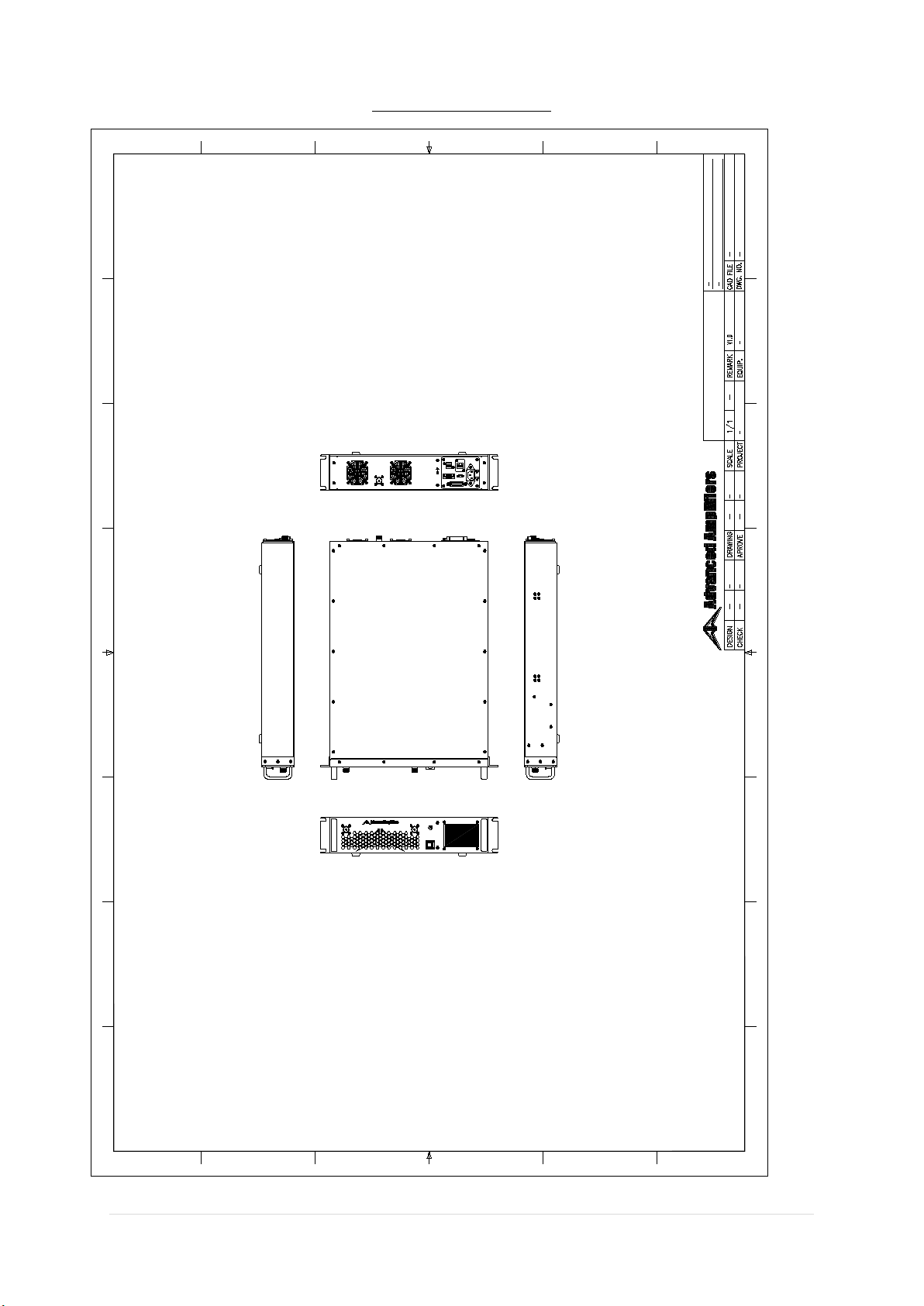
SYSTEM OUTLINE VIEW
AA-20M1G-50 SYSTEM OUTLINE
POWER
ONOFF
FAULT
0dBm Inp utRF Sample
100 ~ 240 VAC
50/60Hz
ETHERNET
DEBUG RS-422
USB
GPIB
112
1324
50Ω Output
AA-20M1G- 50
AA-20M1G- 50

10 | Page - Ver. 1.0
SYSTEM BLOCK DIAGRAM
AA-20M1G-50 BLOCK DIAGRAM
TEMP MONITOR
CURR MONITOR
ENABLE
ATTEN C ONTROL
+5VDC
POWER
LAMP
(GREEN)
LCD
DISPLAY
FAULT
FAULT
LAMP
(RED)
+5VDC
LCD CONTROL
ENABLE
PS+
CURR MONITOR
INPUT DETECT
FWD DETECT
TEMP ALARM
+5VDC
ETHERNET
USB
RS-422
LCD CONTROL
SYSTEM
CONTROLLER
USB
USB
ETHERNET
ETHERNET
BLUETOOTH
RJ45
FEMALE
DEBUG
DUBEG
USB TYPE A
FEMALE
MINI USB
TYPE FEMALE
INPUT MODULE
HPA MODULE COUPLER
MODULE 1
R471-2
FRONT PANEL
REAR PANEL
TEMP MONITOR
ATTEN C ONTROL
PS+
FAN+
FAN 1~5
GPIB
TEMP
SENSOR
TEMP SENSE
+5VDC
+5VDC
RS-232
IEEE-488
CONTROLLER
IEEE-488
IEEE-488
IEEE-488
IEEE-488
FEMALE
INPUT DETECT
+5VDC
E1
RS-422
RS-422
9PIN D-SUB
FEMALE
REF DETECT
R471-1
SW
C: N WHITE
B: L BLACK
A: GND GREEN
N
L
GND POWER SUPPLY
750W V+
V-
PS+
GND
AC 100~240V
50/60Hz
AC INPUT
DEBUG
TEMP SENSE
FAN+
TEMP ALARM
TEMP SENSE
PS+
FAN
CONTROLLER
COUPLER
MODULE 2
FWD DETECT
+5VDC
RF DETECT
MODULE 1
REF DETECT
RF DETECT
MODUEL2
+5VDC
FAULT
FAN+
11 | Page - Ver. 1.0
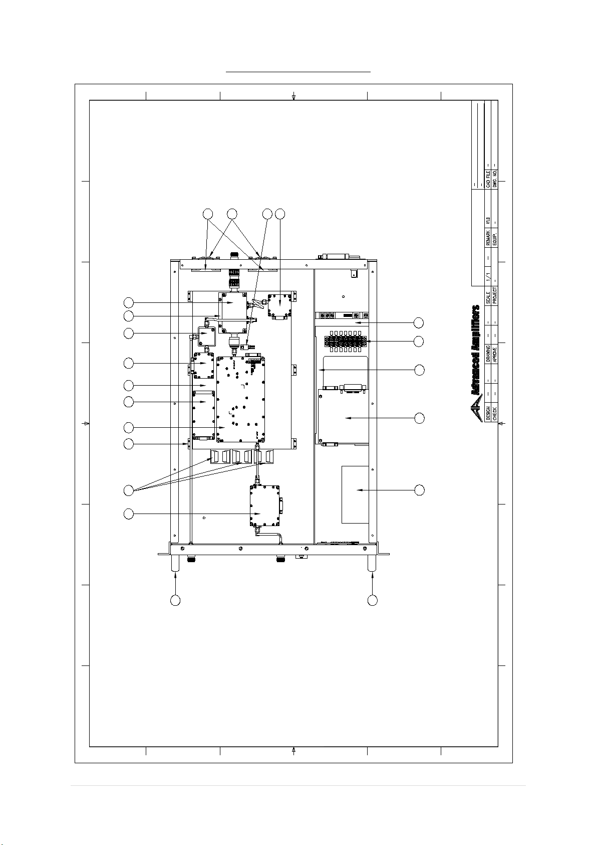
SYSTEM VIEW, TOP INTERIOR
AA-20M1G-50 SYSTEM VIEW-TOP INTERIOR
Top Interior View
M3.0 M3.0 M3.0 M3.0 M3.0 M3.0
1
2
13
14
7
15
17 16
321
11
20
20
12
19
8
14
18
4 5 6 9 10
13

12 | Page - Ver. 1.0
SYSTEM VIEW, BOTTOM INNER
N/A

13 | Page - Ver. 1.0
SYSTEM PARTS LIST
No.
Part Number
Qty.
Description
1
1
Input Module
2
3
40 x 28mm Cooling Fan
3
6
Support 1
4
1
HPA Module
5
1
Fan Controller
6
1
Heat Sink
7
1
RF Detect Module 1
8
1
Coupler Module 2
9
1
Support 2
10
1
Coupler Module 1
11
2
60 x 25mm Cooling Fan
12
2
60mm Cooling Fan Guard
13
1
Temp Sensor
14
1
RF Detect Module 2
15
1
Power Supply
16
1
7P Terminal Block
17
1
Support 3
18
1
GPIB Module
19
1
System Controller
20
2
2U Handle
14 | Page - Ver. 1.0
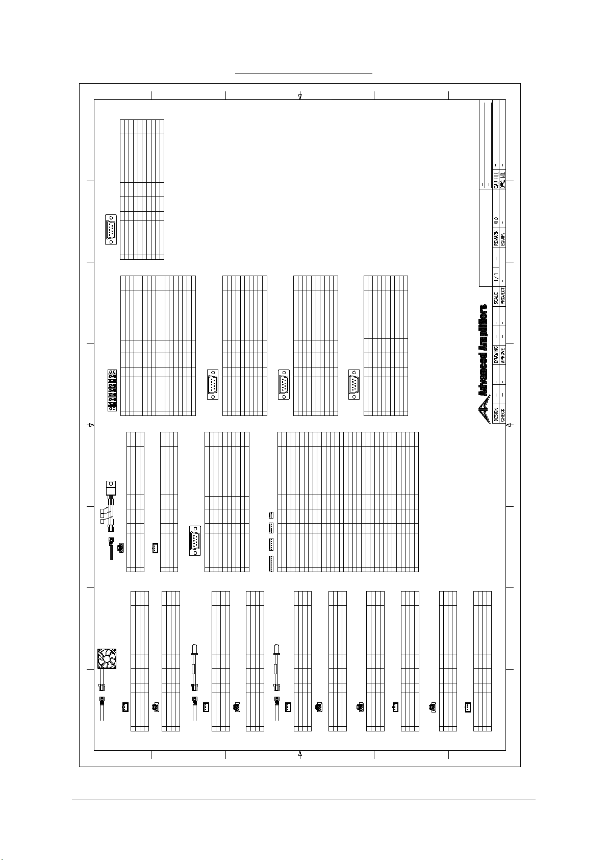
SYSTEM WIRING DIAGRAM
AA-20M1G-50 WIRING DIAGRAM
DESCRIPTION AWG COLOR TO POINT CHECK
FAN +
FAN -
24
24
RED
BLACK
LENGTH
FAN +
FAN -
DESCRIPTION AWG COLOR TO POINT CHECK
FAN +
GND 24
24 YELLOW
BLACK
LENGTH
TERMINAL BLOCK 6A
FAN 1 ~ 5
FAN 1 ~ 5
TERMINAL BLOCK 5A
PIN
1
2
3
PIN
1
2
3
FAULT LAMP +
24 BLACKGND TERMINAL BLOCK 2A
FAULT LAMP + 24 GRAY
DESCRIPTION AWG COLOR TO POINT CHECKLENGTH
POWER LAMP
PIN
1
2
3
DESCRIPTION AWG COLOR TO POINT CHECKLENGTH
POWER LAMP
PIN
1
2
3
DESCRIPTION AWG COLOR TO POINT CHECKLENGTH
FAULT LAMP
PIN
1
2
3
DESCRIPTION AWG COLOR TO POINT CHECKLENGTH
FAULT LAMP
PIN
1
2
3
POWER LAMP + POWER LAMP +
POWER LAMP - POWER LAMP -
24 BLACKGND TERMINAL BLOCK 2A
POWER LAMP + 24 RED TERMINAL BLOCK 3A
24 BLACK
24 RED
24 BLACK
24 GRAY
FAULT LAMP -
FAULT LAMP +
FAULT LAMP -
CON J7-4
R471-2
R471-1
DESCRIPTION AWG COLOR TO POINT CHECK
LENGTH
TERMINAL BLOCK
YELLOW
YELLOW
PIN
1A
1B
PS+
7A
DESCRIPTION AWG COLOR TO POINT
LCD PS+
LCD PS-
24
24
RED
BLACK
LCD PS+
LCD PS-
LCD
PIN
1
2
3
DESCRIPTION AWG COLOR TO POINT
LCD PS+
GND 24
24
BLACK
LCD
PIN
1
2
3
TERMINAL BLOCK 3A
TERMINAL BLOCK 2A
RED
DESCRIPTION AWG COLOR TO POINT
24
24
RED
BLACK
GPIB PS+
GPIB PS-
GPIB
PIN
1
2
3
1A 2A 3A 4A 5A 6A
1B 2B 3B 4B 5B 6B
7A
7B
24
24 FAN CON P6, CON J1-4, J3-3
PS+ POWER SUPPLY V+
2A GND 24 BLACK
FAN CON P9, POWER LAMP P3, FAULT LAMP P3,
CON J3-2, LM35 P2, INPUT MODULEP9,
RF DETECT MODULE 1~2 P9, LCD P3, GPIB P3
2B GND 24 BLACK POWER SUPPLY V-
3A SHUTDOWN 24 GRAY
3B SHUTDOWN 24 GRAY CON J7-5
HPA P5
4A +5V 24 RED
INPUT MODULE P3, LM35 P1, POWER LAMP P1,
RF DETECT MODULE 1~2 P3, LCD P1, GPIB P1
4B +5V 24 RED CON J3-1
5A FAN + 24 YELLOW
FAN CON 55B FAN + 24 YELLOW
FAN 1 ~ 5 P1, CON J1-7
6A GND 24 BLACK
POWER SUPPLY V-6B GND 24 BLACK
FAN 1 ~ 5 P2
7A
PIN
1
2
3
4
5
6
7
8
9
DESCRIPTION AWG COLOR TO POINT
N/C
N/C
N/C
GND
N/C
+5V 24
24 BLACK
RED TERMINAL BLOCK 4A
TERMINAL BLOCK 2A
CHECK
LENGTH
INPUT MODULE
INPUT DETECT 24 WHITE CON J1-3
ATTEN 24 BLUE CON J4-6
N/C
HPA
PIN
DESCRIPTION AWG COLOR TO POINT CHECKLENGTH
GND BLACK
VDD
SHUTDOWN
9
8
20 YELLOW
24
7
6
5
4
1
3
2N/C
N/C
VDD
GND
20 YELLOW
20 BLACK
20
GRAYGRAY24 TERMINAL BLOCK 3A
POWER SUPPLY V-
POWER SUPPLY V-
BROWN24CURRENT MONITOR CON J2-3
TEMP MONITOR CON J2-5
GREEN24
POWER SUPPLY V+
POWER SUPPLY V+
FAN_CURR
J7-1
LOCAL
J7-2
REMOTE
J7-3
FAULT
J7-4
ENABLE
J7-5
TEMP AL_IN
J7-6
J7-7
J7-8
FAN CON P1
TERMINAL BLOCK 4B
GREEN24
GRAY24
GRAY24 FAULT LAMP P1
N/C
PIN
DESCRIPTION AWG COLOR TO POINT CHECKLENGTH
J1-1
FORWARD 1 PURPLE24 RF DETECT MODULE1 P5
CONTROL BOARD (CON)
J1-2
FORWARD 2
J1-3
INPUT DET WHITE24 INPUT MODULE1 P1
VOLTAGE 1 YELLOW24 TERMINAL BLOCK 1A
J1-4
CURRENT 3
J1-5
CURRENT 5
J1-6
VOLTAGE 2
J1-7
J1-8
REFLECTED 1 PURPLE24 RF DETECT MODULE3 P5
J2-1
REFLECTED 2
CURRENT 1
J2-2
BROWN24 HPA P3
CURRENT 2
J2-3
TEMP
J2-4
GREEN24 HPA P4
PS+ YELLOW24 TERMINAL BLOCK 1A
J3-1
GND BLACK24 TERMINAL BLOCK 2A
J3-2
+5VDC RED24 TERMINAL BLOCK 3B
J3-3
COM2_OUT
J4-1
COM2_IN
J4-2
COM1_OUT
J4-3
COM1_IN
J4-4
RF POWER
J4-5
ATTEN
J4-6
BLUE24 INPUT MODULE P5
DESCRIPTION AWG COLOR TO POINT
GND 24
24
BLACK
GPIB
PIN
1
2
3
TERMINAL BLOCK 3A
TERMINAL BLOCK 2A
RED
WHITE CON J1-1DET
PIN
1
2
3
4
5
6
7
8
9
RF DETECT MODULE 1
DESCRIPTION AWG COLOR TO POINT
N/C
N/C
N/C
N/C
GND
N/C
+5V 24
24 BLACK
RED TERMINAL BLOCK 3A
TERMINAL BLOCK 2A
24
/ / /
CURRENT 4
J2-5
GREEN24
J2-6
HEATSINK LM35 P3GREEN24
S/D_IN
S/D_OUT
PIN
1
2
3
4
5
6
7
8
9
FAN CON
DESCRIPTION AWG COLOR TO POINT CHECK
LENGTH
TEMP ALRAM
TEMP SENSE
FAN+
PS+
24
24
24
24
BLACK
YELLOW
GREEN
YELLOW
TERMINAL BLOCK 5B
LM35 P3
TERMINAL BLOCK 1A
TERMINAL BLOCK 2A
LENGTH
LENGTH
LENGTH
LENGTH
CHECK
CHECK
CHECK
CHECK
CHECK
LENGTH
PURPLE CON J1-8DET
PIN
1
2
3
4
5
6
7
8
9
DESCRIPTION AWG COLOR TO POINT
N/C
N/C
N/C
N/C
GND
N/C
+5V 24
24 BLACK
RED TERMINAL BLOCK 3A
TERMINAL BLOCK 2A
24
N/C
CHECK
LENGTH
PIN
1
2
3
DESCRIPTION AWG COLOR TO POINT CHECKLENGTH
LM35 + 24 RED
LM35 - 24 BLACK
TEMP SENSE 24 GREEN
DESCRIPTION AWG COLOR TO POINT CHECKLENGTH
LM35
PIN
1
2
3
+5V 24 RED
GND 24 BLACK
TEMP SENSE 24 GREEN FAN CON P4, CON J2-1
TERMINAL BLOCK 2A
TERMINAL BLOCK 3A
LM35
GND
TEMP SENSE
23
24 GREEN CON J7-6
N/C
N/C
N/C
GND
N/C
RF DETECT MODULE 2
+5V
GPIB PS+
GPIB PS-
GPIB PS+
YELLOW
24 TERMINAL BLOCK 5A
1
15 | Page - Ver. 1.0
APPENDIX 1
LOCAL CONTROLLER LCD INTERFACE
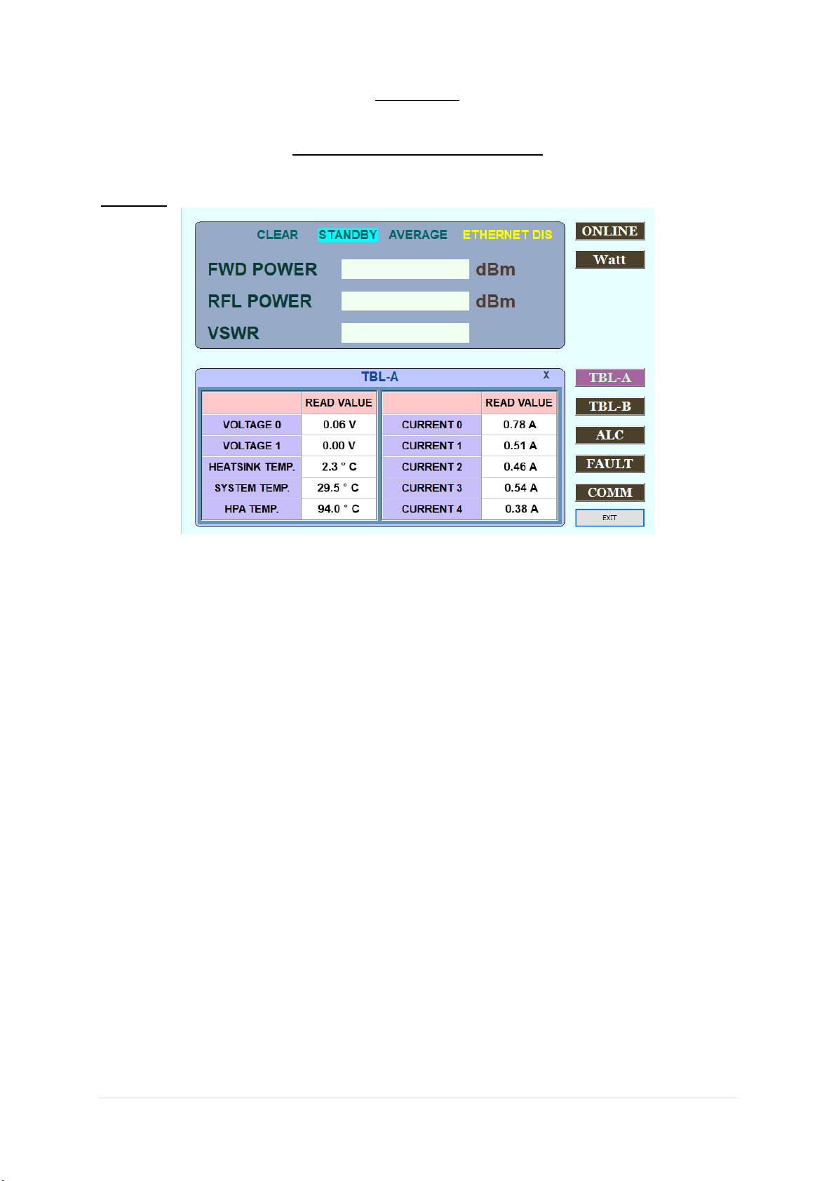
SCREEN 1
(Illustrates unit in standby mode, showing table A parameters, fault indicator on, and output in Watt scale)
ONLINE / STANDBY
When the HPA system starts up, HPA goes into a standby mode. By pressing ONLINE button, unit goes into online
(transmission) mode. ONLINE button will now change & show STANDBY and top middle “Standby” indication will
change to “ONLINE.” By pressing STANDBY button, unit will stop transmitting and go into idle mode (no
transmission).
<NOTE> Internal computer will scan for any possible fault conditions and attempt to clear them BEFORE the
system goes ONLINE. If the system still detects faulty conditions, system will automatically go to STANDBY mode
and will display a RED “FAULT” line which is highlighted left top side of display. An operator should click and
check FAULT menu to review fault conditions. (No FAULT test at the top of the screen next to STANDBY).
FWD POWER
Displays current output of the system.
RFL POWER (or REV POWER)
Displays current reflected power at the output of system.
VSWR
Based on FWD/REV reading, internal computer calculates and displays current VSWR ratio.
TBL (A) (or Table (A))
Pending on system configurations, it will display some or all of below internal system parameters.
System level temperature
Modular (HPA) level temperature
Additional temperature spots
System input level voltage
Modular input level voltage
Current consumption for internal modules or elements
Current consumption for the entire system
Other custom parameters per customer requirements.

16 | Page - Ver. 1.0
SCREEN 2
(Illustrates unit in standby mode, showing table B parameters, fault indicator on, and output in dBm scale)
dBm / Watt
This button enables FWD and RFL POWER readings to be in either WATT or dBm scale.
TBL (B) (or Table (B))
Pending on system configurations, it will display some or all of below internal system parameters.
STANDBY H, _Min Sec
It records total hours (H, M, S) of the system from the moment that an AC power switch is in ON position
RADIATE H, _Min Sec
It records total hours (H, M, S) of the system from the moment that ONLINE button is pushed.
IP
Displays the IP number of the amplifier.
PORT
Displays the Port number.
ALLOWED TIME
Allowed time is the waiting period for TCP port communication (ethernet) between two units.

17 | Page - Ver. 1.0
SCREEN 3
(Illustrates unit in standby mode, showing AGC setting under ALC menu, fault indicator on, and output in dBm
scale)
ATTEN GAIN CONTROL (or ATTENUATING GAIN CONTROL / AGC)
This menu is active when ALC (Automatic Level Control) is OFF. This feature enables an operator to set the total
gain of the system within 20 to 25dB range of maximum gain (If a total system gain is 50dB, maximum attenuation
cannot exceed 50dB).
AG READ
This button recalls and display a current attenuation level.
AG SET
This button sets AGC value entered by an operator to the system.
<NOTE: Operator can always return to no attenuation by setting attenuation value to “0”>
+1, +0.1, -1, -0.1
Operator can set attenuation value by an increment of 1dB or 0.1dB.

18 | Page - Ver. 1.0
SCREEN 4:
(Illustrates unit in standby mode, showing ALC setting under ALC menu, fault indicator on, and output in dBm
scale)
ALC CONTROL (or AUTOMATIC LEVEL CONTROL / ALC)
This menu is active when ALC feature (Automatic Level Control) is ON. This feature enables an operator to set
the total output of the system within 20 to 25dB range at a given output setting (If a total system output is 50dBm,
maximum ALC level cannot be configured above 50dBm).
ALC READ
This button recalls and display a current ALC level.
ALC SET
This button sets ALC value entered by an operator to the system.
<NOTE: Operator can always return to no ALC by pressing “ALC OFF” button>
+1, +0.1, -1, -0.1
Operator can set ALC value by an increment of 1dB or 0.1dB.
ALC OFF / ALC ON
These buttons are used to turn on and off the ALC feature of the system. By default, ALC is OFF unless factory
presetting is set for automatic activation for over power protection feature (If an operator overdrives the system
by mistake, onboard computer may automatically activate ALC feature at preset output level to protect the
system). Please do not turn off ALC feature if an over power protection feature is built in and the ALC feature
activates during maximum output operations.
19 | Page - Ver. 1.0
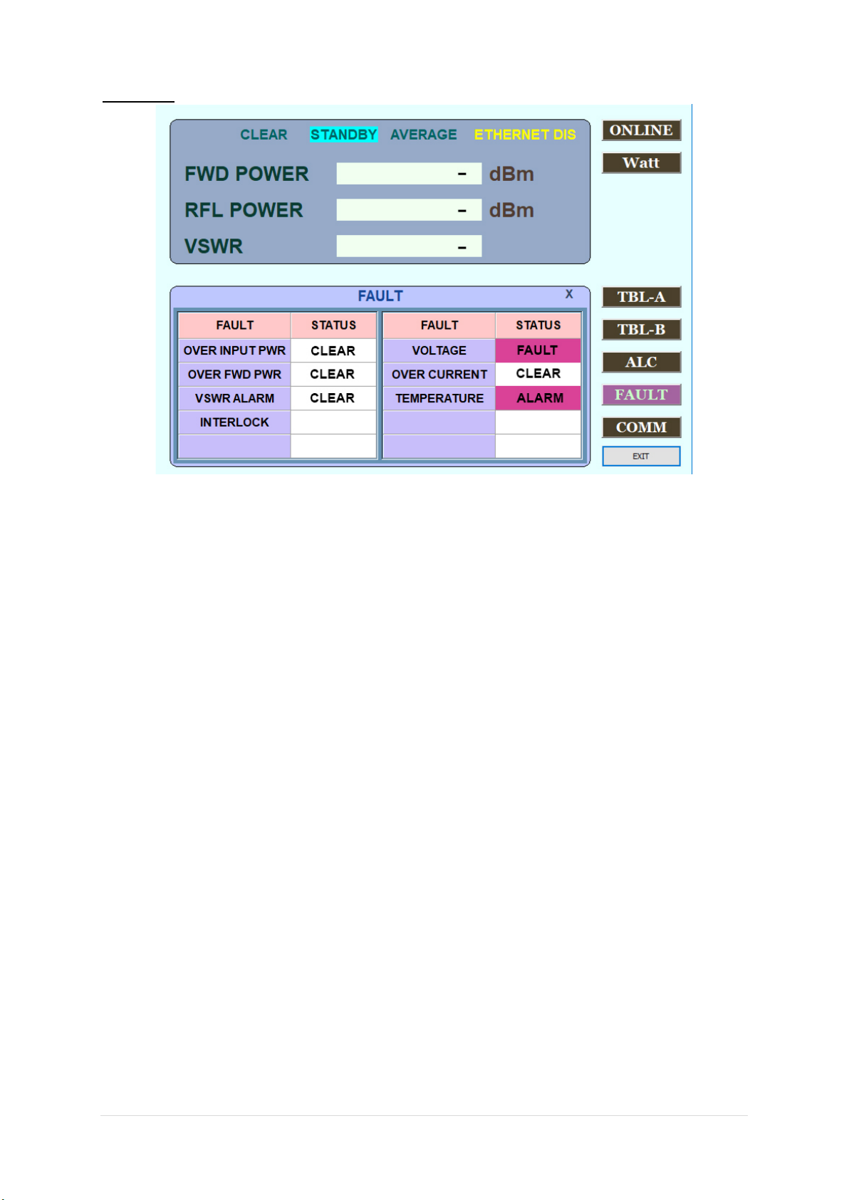
SCREEN 5:
(Illustrates unit in standby mode, showing status windows under FAULT menu, fault indicator on, STAT shows
CLEAR, FAULT, ALARM and output in dBm scale)
FAULT Indications
Pending on system configurations, FAULT section will display some or all of below monitoring parameters.
OVER INPUT POWER
Activates when input power to the system is greater than factory preset safe operating levels.
OVER FWD POWER
Activates when system output power is exceeding factory preset safe operating levels.
VSWR ALARM
Activates when VSWR ratio exceeds factory preset safe operating levels.
INTERLOCK
N/A
VOLTAGE
Activates when irregular input voltages to the internal components are detected.
OVER CURRENT
Activates when irregular current consumption to the internal components are detected.
TEMPERATURE
Activates when irregular temperatures of internal components or system level are detected.
Other custom parameters per customer requirements
STAT (or STATUS)
Under normal operating conditions (no fault), STAT windows will display “CLEAR.”
In an event of fault conditions, STAT windows will change to either “FAULT” or “ALARM” highlighted in RED.
Once fault conditions are corrected, an operator can simply press ONLINE button to clear up fault conditions in
FAULT menu.
<NOTE> Internal computer will scan for any possible fault conditions and automatically attempt to clear them
when ONLINE button is pressed. If the system still detects faulty conditions, system will automatically go to
STANDBY mode and will display “FAULT” or “ALARM” in FAULT menu.
20 | Page - Ver. 1.0
REMOTE CONTROLLER INTERFACE SOFTWARE
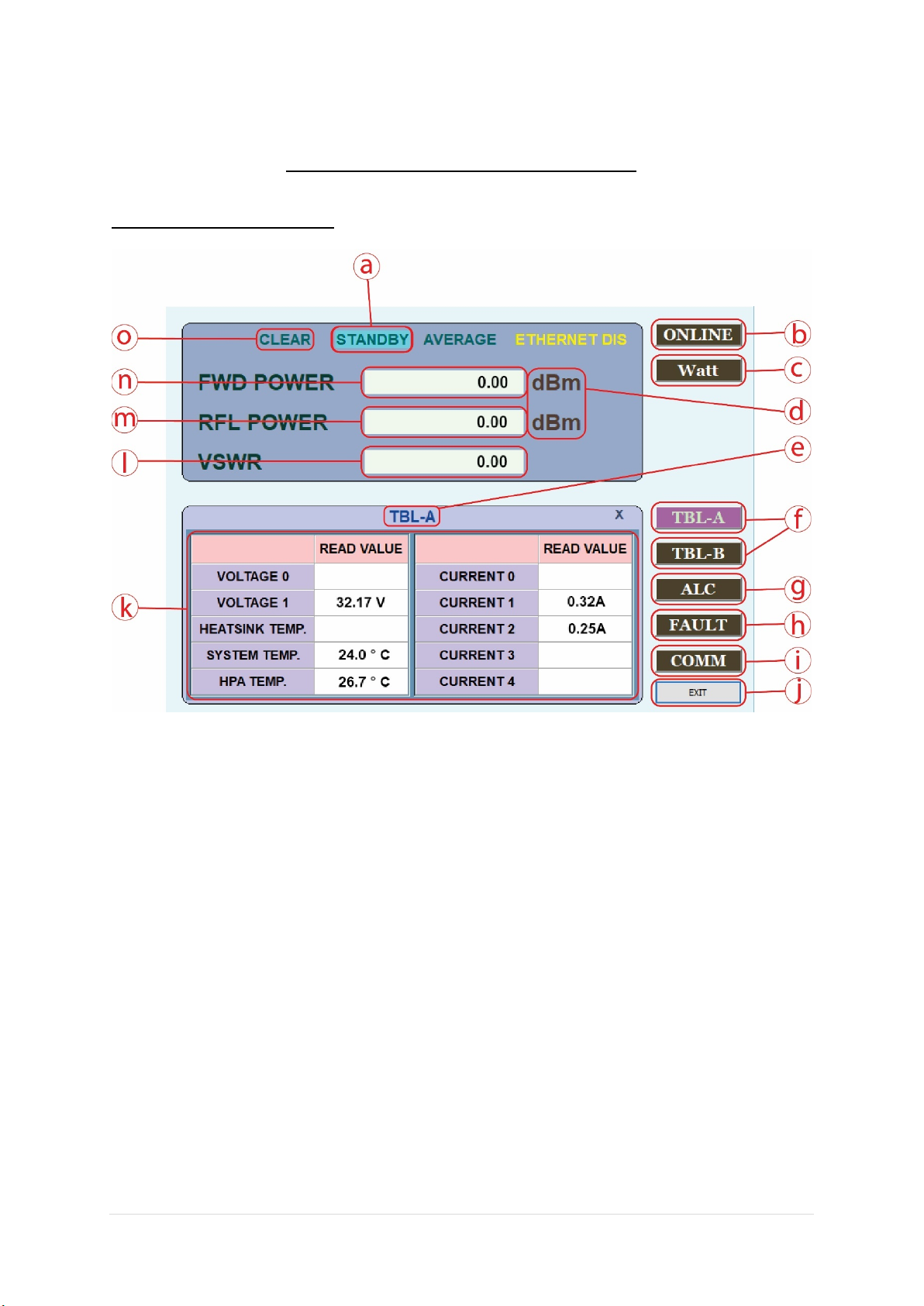
PRIMARY (MAIN) WINDOW
a STANDY/ONLINE: Display system STANDY/ONLINE status.
b ONLINE/STANDY: System ONLINE/STANDY button.
c Watt/dBm: Watt/dBm conversion button.
d dBm/Watt: Display dBm/Watt status.
e TABLE/ALE/FAULT/COMM: Display menu status.
f TABLE: TABLE menu button.
g ALC: ALC menu button.
h FAULT: FAULT menu button.
i COMM: COMM menu button.
j EXIT: Button to exit the program.
k Display status of the TABLE menu window.
l VSWR: Display VSWR value.
m RFL POWER: Display RFL POWER value.
n FWD POWER: Display FWD POWER value.
o CLEAR/FALUT: Display CLEAR/FAULT status.
Table of contents
Other Advanced Amplifiers Amplifier manuals

Advanced Amplifiers
Advanced Amplifiers AA-1M6G-30 User manual

Advanced Amplifiers
Advanced Amplifiers AMP2103P-LC User manual

Advanced Amplifiers
Advanced Amplifiers AA-1218G-3.5KW-PT User manual

Advanced Amplifiers
Advanced Amplifiers AA-10K250M-150 User manual

Advanced Amplifiers
Advanced Amplifiers AA-28G-2KW-PT User manual
Popular Amplifier manuals by other brands


Toa
Toa A-503A Specifications

Friedman
Friedman JJ-100 instruction manual

COM-power corporation
COM-power corporation ARI-6000-100W instruction manual

Dynavector
Dynavector P75 mk4 Instructions and specifications

Microh
Microh MT1201 owner's manual

Jensen Audio
Jensen Audio Power 2000.1 D Installation & operation manual