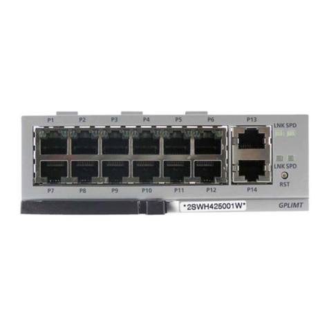
Advanced Energy Thyro-PX Anybus Modbus TCP User manual

Thyro-PX™Anybus® Modbus TCP
Guide
57010166-00A January 2017
Related Documentation
For complete information on the Thyro-PX unit,
see the user manual that accompanied the
system. In particular, reference the safety
information in Chapter 1 of the user manual for
the Thyro-PX unit.
ANYBUS MODBUS TCP MODULE
The Anybus Modbus TCP module is an optional accessory for the Thyro-PX power controller.
Related Links
• “Hardware Description” on page 2
• “Configuring With Thyro-Tool Pro PC Software” on page 3
• “Default Flexible Links” on page 7
• “Installing Optional Modules” on page 8
• “Fast Process Data Communication” on page 9
• “Modbus TCP Parameter List” on page 13
• “AE Global Services” on page 34
This document and the information contained herein are the proprietary property of Advanced
Energy Industries, Inc. Copyright© 2017 Advanced Energy Industries, Inc. All Rights Reserved.

HARDWARE DESCRIPTION
This module is compliant with the Modbus® TCP standard.
Link/activity port 2
Link/activity port 1
Network status
RJ-45 connectors
Module status
Figure 1. Hardware
Table 1. Network status LED
LED State Description
Off No IP address or exception state
Green At least one Modbus message received
Green, blinking Waiting for first Modbus message
Red IP address conflict detected, fatal error
Red, blinking Connection timeout. No Modbus message has been received
within the configured “process active timeout” time.
Table 2. Module status LED
LED State Description
Off No power
Green Normal operation
Red Major fault, fatal error
Red, blinking Minor fault
Alternating red/green Firmware update in progress
If both the network status LED and the module status LED are red, a fatal error has occurred.
Table 3. Link/activity LED
LED State Description
Off No link
Green 100 Mbit/s link established
Advanced Energy®Thyro-PX™Anybus® Modbus TCP
57010166-00A Thyro-PX™Anybus® Modbus TCP 2

Table 3. Link/activity LED (Continued)
LED State Description
Green, flickering 100 Mbit/s activity
Yellow 10 Mbit/s link established
Yellow, flickering 10 Mbit/s activity
Table 4. RJ-45 Ethernet pinout
Pin Description
1 TD+
2 TX-
3 RX+
6 RX-
4, 5, 7, 8 Normally left unused; to ensure signal integrity, these pins
are tied together and terminated to PE via a filter circuit in
the module.
Housing Cable shield
CONFIGURING WITH THYRO-TOOL PRO PC
SOFTWARE
You can configure the Thyro-PX power controller using either the Thyro-Tool Pro PC software or the
Thyro‑Touch display.
To configure the unit, you will:
• Adapt the Thyro-PX hardware configuration
If required, you can also:
• Select the configuration
• Configure the diagnostics
• Configure the flexible link parameters
Adapting Thyro-PX Hardware Configuration
Open parameter file with the unit online in the Port Explorer tab of the Thyro-Tool Pro PC software,
or use the Thyro‑Touch display.
Set the Anybus module slot to Modbus TCP in the Thyro-PX device hardware configuration:
Advanced Energy®Thyro-PX™Anybus® Modbus TCP
57010166-00A Thyro-PX™Anybus® Modbus TCP 3

Figure 2. Menu tree
Anybus Parameter Group
When the computer is connected to the Thyro-PX power controller, the Anybus parameter group will
be added to the parameter list after updating the hardware configuration, as shown in the previous
figure.
If the unit is not available for online configuration, the software can also be configured offline.
Contact AE Global Services to obtain a parameter file appropriate to your hardware configuration.
Figure 3. Anybus parameter group
Configuring Modbus TCP IP Address
Set the Modbus TCP IP address in the submenu Modbus_TCP. By default, the IP address is
automatically assigned through the Dynamic Host Configuration Protocol (DHCP) server.
Advanced Energy®Thyro-PX™Anybus® Modbus TCP
57010166-00A Thyro-PX™Anybus® Modbus TCP 4

Figure 4. Configure Modbus TCP IP address
Connecting to the Modbus TCP controller
Some process control software can scan the network to automatically detect and connect to Modbus
TCP devices.
To manually configure the process control software, find the MAC address for the Modbus TCP
module in the General menu. Use the MAC address to configure the process control software.
Figure 5. Modbus TCP module MAC address
Advanced Energy®Thyro-PX™Anybus® Modbus TCP
57010166-00A Thyro-PX™Anybus® Modbus TCP 5

Selecting Configuration
Figure 6. Select configuration
Each configuration name, status, and selection is described in the following table:
Table 5. Configuration
Name Status/Selection Description
Control of validity Cyclic telegram valid
only if bit is set
When enabled, the cyclic telegrams received from the
master will only be considered as valid and processed
if bit 15 of the Device Command (API # 41) is set.
This function allows several settings to be changed one
after another before enabling the complete change,
thereby avoiding unwanted effects due to an
incomplete change.
Motorpotentiometer =
Master
Motorpotentiometer =
Master
When enabled, the value of the motorpotentiometer
continuously follows the master setpoint while in
remote operation, so that no setpoint leap occurs
during the switch-over to the local setpoint.
Setpoint Error Zero Zero is used as the setpoint when the master setpoint is
missing.
Last valid master
setpoint
The last valid master setpoint is used as the setpoint
when the master setpoint is missing.
Last valid error setpoint The last valid error setpoint is used as the setpoint
when the master setpoint is missing.
Local remote
configuration
Unchanged behavior Configuration of the master's influence to the local
remote behavior.
Automatic switch to local The unit will automatically switch to local mode when
the communication with master is interrupted.
Ignore master in local When the unit is in local mode, data and commands
from the master will be ignored.
Advanced Energy®Thyro-PX™Anybus® Modbus TCP
57010166-00A Thyro-PX™Anybus® Modbus TCP 6

Configuring Diagnostics
Modbus TCP diagnostic information is available according to the following tables.
Table 6.
Input Register Dec Hex
Diagnostic event count 2048 800 Number of pending diagnostic events. There may be gaps between
active diagnostic events. Inactive diagnostic events return 0000h
when read.
Diagnostic event #1 2049 801 High byte = severity
Low byte = event code
Diagnostic event #2 2050 802
Diagnostic event #3 2051 803
Diagnostic event #4 2052 804
Diagnostic event #5 2053 805
Diagnostic event #6 2054 806
The following two diagnostic events are supported:
Table 7. Diagnostic events
Event Code Event
0x10 (= 16) Error
0x40 (= 64) Temperature
You can configure both events in the Thyro-Tool Pro PC software. You can add any Thyro-PX error
or status message. Once an error or status message is added, the message will trigger the
corresponding extended diagnosis event.
Configuring Flexible Link Parameters
The flexible link parameters have been designed to allow access to Thyro-PX internal data, such as
parameters and actual values, that are not listed in the parameter list.
There are 20 flexible link parameters for writing and 20 flexible link parameters for reading data.
The default read links are shown in the Thyro-Tool Pro PC software, and in the table “Default
Flexible Links”.
Once the respective data point has been selected in the flexible link parameter configuration, it can be
accessed on the Modbus TCP using the respective flexible link parameter API that is listed in the
parameter list (see ).
Default Flexible Links
Advanced Energy®Thyro-PX™Anybus® Modbus TCP
57010166-00A Thyro-PX™Anybus® Modbus TCP 7

Table 8. Default flexible links
Flexible Link Default Link Setting
Flexible read-link 01 r Power Controller #1: Total power - read
Flexible read-link 02 r Power Controller #1: L1 Urms - read
Flexible read-link 03 r Power Controller #1: L1 Irms - read
Flexible read-link 04 r Power Controller #1: L1 Power - read
Flexible read-link 05 r Power Controller #1: L1 Resistance - read
Flexible read-link 06 r Power Controller #1: L1 Umains - read
Flexible read-link 07 r Power Controller #1: L1 Temperature - read
Flexible read-link 08 r Power Controller #1: L2 Urms - read
Flexible read-link 09 r Power Controller #1: L2 Irms - read
Flexible read-link 10 r Power Controller #1: L2 Power - read
Flexible read-link 11 r Power Controller #1: L2 Resistance - read
Flexible read-link 12 r Power Controller #1: L2 Umains - read
Flexible read-link 13 r Power Controller #1: L2 Temperature - read
Flexible read-link 14 r Power Controller #1: L3 Urms - read
Flexible read-link 15 r Power Controller #1: L3 Irms - read
Flexible read-link 16 r Power Controller #1: L3 Power - read
Flexible read-link 17 r Power Controller #1: L3 Resistance - read
Flexible read-link 18 r Power Controller #1: L3 Umains - read
Flexible read-link 19 r Power Controller #1: L3 Temperature - read
Flexible read-link 20 r Not applicable
INSTALLING OPTIONAL MODULES
DANGER:
RISK OF DEATH OR BODILY INJURY. Disconnect and lockout/tagout all sources of input
power before working on this unit or anything connected to it.
DANGER:
RISQUE DE MORT OU DE BLESSURES CORPORELLES. Débrancher et verrouiller/
étiqueter toutes les sources de puissance d’entrée avant de travailler sur cette unité ou sur
tout élément qui y est raccordé.
The optional modules may be shipped separately.
1. Verify that the unit is disconnected from all power sources.
Advanced Energy®Thyro-PX™Anybus® Modbus TCP
57010166-00A Thyro-PX™Anybus® Modbus TCP 8

2. Unpack each optional module at an ESD safe work space.
3. Plug each optional module into the unit.
When an Anybus module is inserted into the unit, guide the module towards the left during
insertion.
4. Secure each module with the two TORX® T8 screws provided with the module.
If an Anybus module must be removed from the unit, loosen the TORX T8 mounting screws 3 turns,
and pry out the module with a small flat-bladed screwdriver, as shown in the following figure.
Figure 7. Anybus module removal
FAST PROCESS DATA COMMUNICATION
For fast communication, some process data are buffered in the communication module. To read or
write a buffered parameter, use the address in the following tables, rather than the API associated
address in table “Modbus TCP Parameter List” on page 13.
☞ Important
The parameter assigned to each address changes depending on how the Thyro-PX power
controller is configured.
Buffered Read Addresses
The parameter assigned to each address changes with each of the following configurations:
• Single-phase (1 * 1 phase)
• 2x single-phase (2 * 1 phase)
• 3x single-phase (3 * 1 phase)
• Three-phase economic circuit (two phase) (1 * 2 phase)
Advanced Energy®Thyro-PX™Anybus® Modbus TCP
57010166-00A Thyro-PX™Anybus® Modbus TCP 9

• Three-phase (1 * 3 phase)
Use the column in the following table which corresponds with your hardware configuration. For the
default flexible links, see “Default Flexible Links” on page 7.
Table 9. Buffered read addresses
Address Read Parameter by Thyro-PX Configuration
Dec Hex 1 * 1 phase 2 * 1 phase 3 * 1 phase 1 * 2 phase 1 * 3 phase
2048 800 Device Error
device r
Device Error
device r
Device Error
device r
Device Error
device r
Device Error
device r
2050 802 Device Error
extension r
Device Error
extension r
Device Error
extension r
Device Error
extension r
Device Error
extension r
2052 804 #1 Actual setpoint
r
#1 Actual setpoint
r
#1 Actual
setpoint r
#1 Actual setpoint
r
#1 Actual setpoint
r
2054 806 #1 Output r #1 Output r #1 Output r #1 Output r #1 Output r
2056 808 #1 Error PC r #1 Error PC r #1 Error PC r #1 Error PC r #1 Error PC r
2058 80A #1 Status PC r #1 Status PC r #1 Status PC r #1 Status PC r #1 Status PC r
2060 80C #1 Monitoring PC
r
#1 Monitoring PC
r
#1 Monitoring PC
r
#1 Monitoring PC
r
#1 Monitoring PC
r
2062 80E Flexible link 01 r
[1]
#2 Actual setpoint
r
#2 Actual
setpoint r
Flexible link 01 r Flexible link 01 r
2064 810 Flexible link 02 r #2 Output r #2 Output r Flexible link 02 r Flexible link 02 r
2066 812 Flexible link 03 r #2 Error PC r #2 Error PC r Flexible link 03 r Flexible link 03 r
2068 814 Flexible link 04 r #2 Status PC r #2 Status PC r Flexible link 04 r Flexible link 04 r
2070 816 Flexible link 05 r #2 Monitoring PC
r
#2 Monitoring PC
r
Flexible link 05 r Flexible link 05 r
2072 818 Flexible link 06 r Flexible link 01 r #3 Actual
setpoint r
Flexible link 06 r Flexible link 06 r
2074 81A Flexible link 07 r Flexible link 02 r #3 Output r Flexible link 07 r Flexible link 07 r
2076 81C Flexible link 08 r Flexible link 03 r #3 Error PC r Flexible link 08 r Flexible link 08 r
2078 81E Flexible link 09 r Flexible link 04 r #3 Status PC r Flexible link 09 r Flexible link 09 r
2080 820 Flexible link 10 r Flexible link 05 r #3 Monitoring PC
r
Flexible link 10 r Flexible link 10 r
2082 822 Flexible link 11 r Flexible link 06 r Flexible link 01 r Flexible link 11 r Flexible link 11 r
2084 824 Flexible link 12 r Flexible link 07 r Flexible link 02 r Flexible link 12 r Flexible link 12 r
2086 826 Flexible link 13 r Flexible link 08 r Flexible link 03 r Flexible link 13 r Flexible link 13 r
2088 828 Flexible link 14 r Flexible link 09 r Flexible link 04 r Flexible link 14 r Flexible link 14 r
2090 82A Flexible link 15 r Flexible link 10 r Flexible link 05 r Flexible link 15 r Flexible link 15 r
2092 82C Flexible link 16 r Flexible link 11 r Flexible link 06 r Flexible link 16 r Flexible link 16 r
2094 82E Flexible link 17 r Flexible link 12 r Flexible link 07 r Flexible link 17 r Flexible link 17 r
Advanced Energy®Thyro-PX™Anybus® Modbus TCP
57010166-00A Thyro-PX™Anybus® Modbus TCP 10

Table 9. Buffered read addresses (Continued)
Address Read Parameter by Thyro-PX Configuration
Dec Hex 1 * 1 phase 2 * 1 phase 3 * 1 phase 1 * 2 phase 1 * 3 phase
2096 830 Flexible link 18 r Flexible link 13 r Flexible link 08 r Flexible link 18 r Flexible link 18 r
2098 832 Flexible link 19 r Flexible link 14 r Flexible link 09 r Flexible link 19 r Flexible link 19 r
2100 834 Flexible link 20 r Flexible link 15 r Flexible link 10 r Flexible link 20 r Flexible link 20 r
2102 836 Flexible link 16 r Flexible link 11 r
2104 838 Flexible link 17 r Flexible link 12 r
2106 83A Flexible link 18 r Flexible link 13 r
2108 83C Flexible link 19 r Flexible link 14 r
2110 83E Flexible link 20 r Flexible link 15 r
2112 840 Flexible link 16 r
2114 842 Flexible link 17 r
2116 844 Flexible link 18 r
2118 846 Flexible link 19 r
2120 848 Flexible link 20 r
1 See “Default Flexible Links” on page 7
Buffered Write Addresses
The parameter assigned to each address changes with each of the following configurations:
•Single-phase (1 * 1 phase)
• 2x single-phase (2 * 1 phase)
• 3x single-phase (3 * 1 phase)
• Three-phase economic circuit (two phase) (1 * 2 phase)
• Three-phase (1 * 3 phase)
Use the column in the following table which corresponds with your hardware configuration. For the
default flexible links, see “Default Flexible Links” on page 7.
Table 10. Buffered write addresses
Address Write Parameter by Thyro-PX Configuration
Dec Hex 1 * 1 phase 2 * 1 phase 3 * 1 phase 1 * 2 phase 1 * 3 phase
0 0 Device
Commands w
Device
Commands w
Device
Commands w
Device
Commands w
Device
Commands w
1 1 #1 Fieldbus
setpoint w
#1 Fieldbus
setpoint w
#1 Fieldbus
setpoint w
#1 Fieldbus
setpoint w
#1 Fieldbus
setpoint w
Advanced Energy®Thyro-PX™Anybus® Modbus TCP
57010166-00A Thyro-PX™Anybus® Modbus TCP 11

Table 10. Buffered write addresses (Continued)
Address Write Parameter by Thyro-PX Configuration
Dec Hex 1 * 1 phase 2 * 1 phase 3 * 1 phase 1 * 2 phase 1 * 3 phase
3 3 #1 Error setpoint
w
#1 Error setpoint
w
#1 Error setpoint
w
#1 Error setpoint
w
#1 Error setpoint
w
5 5 Flexible link 01 w
[1]
#2 Fieldbus
setpoint w
#2 Fieldbus
setpoint w
Flexible link 01 w Flexible link 01 w
7 7 Flexible link 02 w #2 Error setpoint
w
#2 Error setpoint
w
Flexible link 02 w Flexible link 02 w
9 9 Flexible link 03 w Flexible link 01
w
#3 Fieldbus
setpoint w
Flexible link 03 w Flexible link 03 w
11 B Flexible link 04 w Flexible link 02
w
#3 Error setpoint
w
Flexible link 04 w Flexible link 04 w
13 D Flexible link 05 w Flexible link 03
w
Flexible link 01 w Flexible link 05 w Flexible link 05 w
15 F Flexible link 06 w Flexible link 04
w
Flexible link 02 w Flexible link 06 w Flexible link 06 w
17 11 Flexible link 07 w Flexible link 05
w
Flexible link 03 w Flexible link 07 w Flexible link 07 w
19 13 Flexible link 06
w
Flexible link 04 w
21 15 Flexible link 07
w
Flexible link 05 w
23 17 Flexible link 06 w
25 19 Flexible link 07 w
1 See “Default Flexible Links” on page 7
Advanced Energy®Thyro-PX™Anybus® Modbus TCP
57010166-00A Thyro-PX™Anybus® Modbus TCP 12

MODBUS TCP PARAMETER LIST
Table 11. Parameter list
API
#
Read /
Write
Address Parameter Name Type Parameter Description
Dec Hex
1 Read 4112 1010 Flexible link 01 r UINT32
FLOAT
Flexible link number 01 - read
2 Read 4114 1012 Flexible link 02 r UINT32
FLOAT
Flexible link number 02 - read
3 Read 4116 1014 Flexible link 03 r UINT32
FLOAT
Flexible link number 03 - read
4 Read 4118 1016 Flexible link 04 r UINT32
FLOAT
Flexible link number 04 - read
5 Read 4120 1018 Flexible link 05 r UINT32
FLOAT
Flexible link number 05 - read
6 Read 4122 101A Flexible link 06 r UINT32
FLOAT
Flexible link number 06 - read
7 Read 4124 101C Flexible link 07 r UINT32
FLOAT
Flexible link number 07 - read
8 Read 4126 101E Flexible link 08 r UINT32
FLOAT
Flexible link number 08 - read
9 Read 4128 1020 Flexible link 09 r UINT32
FLOAT
Flexible link number 09 - read
10 Read 4130 1022 Flexible link 10 r UINT32
FLOAT
Flexible link number 10 - read
11 Read 4132 1024 Flexible link 11 r UINT32
FLOAT
Flexible link number 11 - read
12 Read 4134 1026 Flexible link 12 r UINT32
FLOAT
Flexible link number 12 - read
13 Read 4136 1028 Flexible link 13 r UINT32
FLOAT
Flexible link number 13 - read
14 Read 4138 102A Flexible link 14 r UINT32
FLOAT
Flexible link number 14 - read
15 Read 4140 102C Flexible link 15 r UINT32
FLOAT
Flexible link number 15 - read
16 Read 4142 102E Flexible link 16 r UINT32
FLOAT
Flexible link number 16 - read
Advanced Energy®Thyro-PX™Anybus® Modbus TCP
57010166-00A Thyro-PX™Anybus® Modbus TCP 13

Table 11. Parameter list (Continued)
API
#
Read /
Write
Address Parameter Name Type Parameter Description
Dec Hex
17 Read 4144 1030 Flexible link 17 r UINT32
FLOAT
Flexible link number 17 - read
18 Read 4146 1032 Flexible link 18 r UINT32
FLOAT
Flexible link number 18 - read
19 Read 4148 1034 Flexible link 19 r UINT32
FLOAT
Flexible link number 19 - read
20 Read 4150 1036 Flexible link 20 r UINT32
FLOAT
Flexible link number 20 - read
21 Write 4152 1038 Flexible link 01 w UINT32
FLOAT
Flexible link number 01 - write
22 Write 4154 103A Flexible link 02 w UINT32
FLOAT
Flexible link number 02 - write
23 Write 4156 103C Flexible link 03 w UINT32
FLOAT
Flexible link number 03 - write
24 Write 4158 103E Flexible link 04 w UINT32
FLOAT
Flexible link number 04 - write
25 Write 4160 1040 Flexible link 05 w UINT32
FLOAT
Flexible link number 05 - write
26 Write 4162 1042 Flexible link 06 w UINT32
FLOAT
Flexible link number 06 - write
27 Write 4164 1044 Flexible link 07 w UINT32
FLOAT
Flexible link number 07 - write
28 Write 4166 1046 Flexible link 08 w UINT32
FLOAT
Flexible link number 08 - write
29 Write 4168 1048 Flexible link 09 w UINT32
FLOAT
Flexible link number 09 - write
30 Write 4170 104A Flexible link 10 w UINT32
FLOAT
Flexible link number 10 - write
31 Write 4172 104C Flexible link 11 w UINT32
FLOAT
Flexible link number 11 - write
32 Write 4174 104E Flexible link 12 w UINT32
FLOAT
Flexible link number 12 - write
33 Write 4176 1050 Flexible link 13 w UINT32
FLOAT
Flexible link number 13 - write
34 Write 4178 1052 Flexible link 14 w UINT32
FLOAT
Flexible link number 14 - write
35 Write 4180 1054 Flexible link 15 w UINT32
FLOAT
Flexible link number 15 - write
Advanced Energy®Thyro-PX™Anybus® Modbus TCP
57010166-00A Thyro-PX™Anybus® Modbus TCP 14

Table 11. Parameter list (Continued)
API
#
Read /
Write
Address Parameter Name Type Parameter Description
Dec Hex
36 Write 4182 1056 Flexible link 16 w UINT32
FLOAT
Flexible link number 16 - write
37 Write 4184 1058 Flexible link 17 w UINT32
FLOAT
Flexible link number 17 - write
38 Write 4186 105A Flexible link 18 w UINT32
FLOAT
Flexible link number 18 - write
39 Write 4188 105C Flexible link 19 w UINT32
FLOAT
Flexible link number 19 - write
40 Write 4190 105E Flexible link 20 w UINT32
FLOAT
Flexible link number 20 - write
41 Write 4192 1060 Device Commands w UINT16 Device command - write
Bit 0: Clear energy counter power
controller #1
Bit 1: Clear energy counter power
controller #2
Bit 2: Clear energy counter power
controller #3
Bit 3: Regulator lock power controller
#1
Bit 4: Regulator lock power controller
#2
Bit 5: Regulator lock power controller
#3
Bit 6: Pulse lock power controller #1
Bit 7: Pulse lock power controller #2
Bit 8: Pulse lock power controller #3
Bit 9: External Error 1
Bit 10: External Error 2
Bit 11: External Error 3
Bit 12: Load parameters (from
EEPROM to Flash)
Bit 13: Save parameters (from Flash to
EEPROM)
Bit 14: Fault acknowledgement (Quit)
Bit 15: "Only if bit set" (special
function)
42 4194 1062
43 Read 4196 1064 Device operating hours r FLOAT Operating hours - read
Advanced Energy®Thyro-PX™Anybus® Modbus TCP
57010166-00A Thyro-PX™Anybus® Modbus TCP 15

Table 11. Parameter list (Continued)
API
#
Read /
Write
Address Parameter Name Type Parameter Description
Dec Hex
44 Read 4198 1066 Device CPU temperature
r
FLOAT CPU temperature - read
45 Read 4200 1068 Device error r UINT32 Error - read
Bit 0: Aux. supply error
Bit 1: Parameter error
Bit 2: Frequency error
Bit 3: Internal communication error
Bit 4: Temperature CPU too high
Bit 8: Phase L1 missing
Bit 9: Phase L2 missing
Bit 10: Phase L3 missing
Bit 11: Fuse 1 broken
Bit 12: Fuse 2 broken
Bit 13: Fuse 3 broken
Bit 14: Thyristor 1 short-circuit
Bit 15: Thyristor 2 short-circuit
Bit 16: Thyristor 3 short-circuit
Bit 17: External error 1 (customer-
specific)
Bit 18: External error 2 (customer-
specific)
Bit 19: External error 3 (customer-
specific)
Bit 21: Extension card X53
configuration error
Bit 22: Extension card X54
configuration error
Bit 23: External extension 1
configuration error
Bit 24: External extension 2
configuration error
Bit 25: dASM card configuration error
Bit 26: Anybus configuration error
Bit 27: Internal error
Advanced Energy®Thyro-PX™Anybus® Modbus TCP
57010166-00A Thyro-PX™Anybus® Modbus TCP 16

Table 11. Parameter list (Continued)
API
#
Read /
Write
Address Parameter Name Type Parameter Description
Dec Hex
46 Read 4202 106A Device error extension r UINT32 Error extension - read
Bit 1: Extension card X53 error
Bit 2: Extension card X54 error
Bit 3: External extension 1 error
Bit 4: External extension 2 error
Bit 5: dASM card error
Bit 6: Anybus module error
Bit 8: dASM total power exceeded
Bit 9: dASM count error
47 4204 106C
48 Read 4206 106E #1 Analog setpoint r FLOAT Power controller #1: Analog setpoint -
read
49 Read 4208 1070 #1 Motor pot. setpoint r FLOAT Power controller #1: Motor
potentiometer setpoint - read
50 Write 4210 1072 #1 Fieldbus setpoint w FLOAT Power controller #1: Fieldbus setpoint -
write
51 Read 4212 1074 #1 Actual setpoint r FLOAT Power controller #1: Actual setpoint -
read
52 Write 4214 1076 #1 Error setpoint w FLOAT Power controller #1: Error setpoint -
write
53 Read 4216 1078 #1 Total power r FLOAT Power controller #1: Total power - read
54 Read 4218 107A #1 Alpha r FLOAT Power controller #1: Alpha - read
55 Read 4220 107C #1 TimeOn r FLOAT Power controller #1: Time on - read
56 Read 4222 107E #1 Output r FLOAT Power controller #1: Output - read
57 Read 4224 1080 #1 Frequency r FLOAT Power controller #1: Frequency - read
58 Read 4226 1082 #1 Energy counter r FLOAT Power controller #1: Energy counter -
read
Advanced Energy®Thyro-PX™Anybus® Modbus TCP
57010166-00A Thyro-PX™Anybus® Modbus TCP 17

Table 11. Parameter list (Continued)
API
#
Read /
Write
Address Parameter Name Type Parameter Description
Dec Hex
59 Read 4228 1084 #1 Error PC r UINT32 Error PC - read
Bit 4: Synchronization error
Bit 5: Phase missing
Bit 6: Fuse broken
Bit 7: Thyristor short circuit
Bit 16: Internal communication error
Bit 17: U clipping
Bit 18: I clipping
Bit 19: Negative power
Bit 20: Temperature probe error
Bit 21: Overtemperature
Bit 24: I/O error
60 Read 4230 1086 #1 Status PC r UINT32 Power controller #1: Status PC - read
Bit 0: Output (pulses) on
Bit 1: Power controller OK)
Bit 2: Mains OK
Bit 3: Remote setpoint
Bit 6: Pulse lock (with ack.)
Bit 7: Pulse lock (auto-ack.)
Bit 8: Regulator lock
Bit 12: Left rotation field
Bit 13: Output restricted
Bit 14: Max output reached
Bit 16: Active limit
Bit 17: U limit
Bit 18: I limit
Bit 19: Ipeak limit
Bit 20: P limit
Bit 21: Temperature limit
Bit 22: Limit external feedback signal
Bit 24: RAMP starting mode
Bit 25: MOSI starting mode
Bit 26: MOSI starting mode IRMS
Bit 27: MOSI starting mode Ipeak
Advanced Energy®Thyro-PX™Anybus® Modbus TCP
57010166-00A Thyro-PX™Anybus® Modbus TCP 18

Table 11. Parameter list (Continued)
API
#
Read /
Write
Address Parameter Name Type Parameter Description
Dec Hex
61 Read 4232 1088 #1 Monitoring PC r UINT32 Power controller #1: Monitoring PC -
read
Bit 4: Umains < minimum
Bit 5: Umains > maximum
Bit 6: URMS < minimum
Bit 7: URMS < maximum
Bit 8: Urect < minimum
Bit 9: Urect > maximum
Bit 11: Upeak > maximum
Bit 14: IRMS < minimum
Bit 15: IRMS > maximum
Bit 16: Irect < minimum
Bit 17: Irect > maximum
Bit 19: Ipeak > maximum
Bit 22: P < minimum
Bit 23: P > maximum
Bit 24: R < minimum
Bit 25: R > maximum
Bit 26: Tdevice < minimum
Bit 27: Tdevice > maximum
Bit 28: Rabs < minimum
Bit 29: Rabs > maximum
Bit 30: Rrel < minimum
Bit 31: Rrel > maximum
62 4234 108A
63 Read 4236 108C #1 L1 Umains r FLOAT Power controller #1: L1 Umains - read
64 Read 4238 108E #1 L1 Urms r FLOAT Power controller #1: L1 URMS - read
65 Read 4240 1090 #1 L1 Urect r FLOAT Power controller #1: L1 Urect - read
66 Read 4242 1092 #1 L1 Upeak r FLOAT Power controller #1: L1 Upeak - read
67 Read 4244 1094 #1 L1 Irms r FLOAT Power controller #1: L1 IRMS - read
68 Read 4246 1096 #1 L1 Irect r FLOAT Power controller #1: L1 Irect - read
69 Read 4248 1098 #1 L1 Ipeak r FLOAT Power controller #1: L1 Ipeak - read
70 Read 4250 109A #1 L1 Power r FLOAT Power controller #1: L1 Power - read
Advanced Energy®Thyro-PX™Anybus® Modbus TCP
57010166-00A Thyro-PX™Anybus® Modbus TCP 19

Table 11. Parameter list (Continued)
API
#
Read /
Write
Address Parameter Name Type Parameter Description
Dec Hex
71 Read 4252 109C #1 L1 Resistance r FLOAT Power controller #1: L1 Resistance -
read
72 Read 4254 109E #1 L1 Temperature r FLOAT Power controller #1: L1 Temperature -
read
73 Read 4256 10A0 #1 L1 External control r FLOAT Power controller #1: L1 External control
- read
74 4258 10A2
75 Read 4260 10A4 #1 L2 Umains r FLOAT Power controller #1: L2 Umains - read
76 Read 4262 10A6 #1 L2 Urms r FLOAT Power controller #1: L2 URMS - read
77 Read 4264 10A8 #1 L2 Urect r FLOAT Power controller #1: L2 Urect - read
78 Read 4266 10AA #1 L2 Upeak r FLOAT Power controller #1: L2 Upeak - read
79 Read 4268 10AC #1 L2 Irms r FLOAT Power controller #1: L2 IRMS - read
80 Read 4270 10AE #1 L2 Irect r FLOAT Power controller #1: L2 Irect - read
81 Read 4272 10B0 #1 L2 Ipeak r FLOAT Power controller #1: L2 Ipeak - read
82 Read 4274 10B2 #1 L2 Power r FLOAT Power controller #1: L2 Power - read
83 Read 4276 10B4 #1 L2 Resistance r FLOAT Power controller #1: L2 Resistance -
read
84 Read 4278 10B6 #1 L2 Temperature r FLOAT Power controller #1: L2 Temperature -
read
85 Read 4280 10B8 #1 L2 External control r FLOAT Power controller #1: L2 External control
- read
86 4282 10BA
87 Read 4284 10BC #1 L3 Umains r FLOAT Power controller #1: L3 Umains - read
88 Read 4286 10BE #1 L3 Urms r FLOAT Power controller #1: L3 URMS - read
89 Read 4288 10C0 #1 L3 Urect r FLOAT Power controller #1: L3 Urect - read
90 Read 4290 10C2 #1 L3 Upeak r FLOAT Power controller #1: L3 Upeak - read
91 Read 4292 10C4 #1 L3 Irms r FLOAT Power controller #1: L3 IRMS - read
92 Read 4294 10C6 #1 L3 Irect r FLOAT Power controller #1: L3 Irect - read
93 Read 4296 10C8 #1 L3 Ipeak r FLOAT Power controller #1: L3 Ipeak - read
94 Read 4298 10CA #1 L3 Power r FLOAT Power controller #1: L3 Power - read
95 Read 4300 10CC #1 L3 Resistance r FLOAT Power controller #1: L3 Resistance -
read
96 Read 4302 10CE #1 L3 Temperature r FLOAT Power controller #1: L3 Temperature -
read
Advanced Energy®Thyro-PX™Anybus® Modbus TCP
57010166-00A Thyro-PX™Anybus® Modbus TCP 20
Table of contents
Other Advanced Energy Control Unit manuals
Popular Control Unit manuals by other brands
quiko
quiko QK-CE220WRL quick start guide

Texas Instruments
Texas Instruments bq76PL536 EVM quick start guide

SPX
SPX APV DELTA PR2 operating manual

Elk Products
Elk Products ELK-PD9 installation instructions

Microchip Technology
Microchip Technology RN4870/71 manual

DMP Electronics
DMP Electronics 714N-POE Installation and programming guide

Allen-Bradley
Allen-Bradley 1771-QRD Installation and user manual

Sensus
Sensus LonWorks TP/FT-10 user manual

Burkert
Burkert 5281 operating instructions

Fluidmaster
Fluidmaster 402CARHR Quick install guide

KLINGER
KLINGER BALLOSTAR KHA Standard Operation Manual

Franke
Franke F5EV1013 Installation and operating instructions