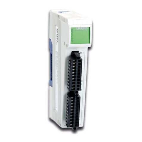
Bastl Sense User manual

Sense can convert and amlif asinal from almost
an te of analo sensor into control voltae and ate
sinals. You can use sensors with variable resistance liht
deendent resistors, bod contacts, water contacts etc. or
sensors that alread outut voltae ulse sensor, accele-
rometer, inductors, iezo etc. amlif them and calibrate
them in the wa to have suitable control voltae and ate
outut sinals.
connectin the sensor
Select whether the signl is voltge (V) or resistnce ()
bsed nd use n pproprite input for the signl.
If you re using very low mplitude voltge (V) signl (such
s n inductor to pick up n electromgnetic field), put
the pre-mp switch into the upper position to increse the
input gin by 50. Note: The pre-mp stge is AC coupled
nd inverting so if you wnt non-inverted signl output use
the “- CV OUT” output.
If you re using ny dedicted (Arduino bsed) nlog
sensor, you cn use the mini pin-heder ptchby to plug
your sensor to the required driving voltge nd connect its
output to the (V) IN voltge input pin on the ptch by.
See the instructions of the specific sensor for more detils.
The (V) IN of the ptch by is normlised to the (V) IN
mono-jck connector.
If you re using resistnce bsed sensor hooked up to
mono-jck cble, this input is simply the two poles of the
resistnce bsed sensor.
Select pullup resistnce similr to the resistnce of your
sensor. The closer the sensor resistnce to the pullup
resistor, the esier it is to clibrte nd gin useful signl.
Just try different settings which work best for you.
controls and oututs
The Gin knob djusts how much gin is pplied
to the input.
The Clipping LEDs show you whether the signl
is mplified too much nd the signl is clipping.
The AC/DC switch selects whether the input is AC or DC
coupled. To simplify it: use AC if you re picking up signls
t udio rte. Use DC coupling for slower signls.
The Offset knob sets the voltge offset pplied to the
signl. When the AC / DC switch is in the DC position the
offset is dded before the gin stge. If the AC/DC switch
is in the AC position the offset is dded fter the gin
stge (see clibrtion).
The CV OUTs output the mplified nd offseted signl.
“CV OUT +” is the non-inverted nd “CV OUT -” is the
inverted version of the signl.
The Threshold knob sets avoltage threshold for
acomparator that outputs gate signals.
The Threshold LEDs indicte Gte signl. They re lso
very useful for clibrtion.
“Gte OUT +” outputs gte when the positive signl
is bove the threshold set by the threshold knob. “Gte
OUT -” outputs gte when the positive signl is below
the threshold.
fatures
voltge nd resistnce inputs
pin heder ptchby for connecting Arduino
comptible sensors (5V or 3V)
resistnce rnge switch
pre-mp for voltge sensors
gin knob with clipping indictor
voltge offset (positive or negtive)
AC or DC coupling for gin stge
threshold for gte outputs
CV output nd inverted CV output
GATE output nd inverted GATE output
technical details
5HP
PTC fuse nd diode protected 10 pin power connector
50mm deep
current +12: <35mA, -12: <25 mA (cn be ffected
by the ctul current drw of the sensor used)
+
+
0
analog sensor calibration
CLIP CLIP
DC
Ω
V
AC GAIN
OFFSET
(V) PRE-AMP
(Ω) RANGE
GATE THRESHOLD
(Ω)IN(V)IN
(V)
IN 5
V3
V
CV OUT
GATE OUT
+
+
+
0
G
N
D
(V) (Ω)
SENSE
Sense
ANALOG SENSOR CALIBRATION MODULE

B e f o r e c o n n e c t i n g t h e r i b b o n c a b l e t o t h i s m o d u l e
d i s c o n n e ct our sstem from ower !
Double check the olarit of the ribbon cable and that
it is not shifted in an direction. The red cable should
be attached to the -12V rail, both on the module and
on the bus board side!
lease make sure of the followin
you hve stndrd pinout eurorck bus bord
you hve +12 nd -12 power rils on tht bus bord
the power rils re not overloded
Although we put protection circuits in the device,
we do not tke ny responsibility for dmges
cused by wrong power supply connection.
After you connected everything, double checked
it nd closed your system so no power lines cn be
touched by your hnd, turn on your system nd
test the module.
!
connectin module to our sstem
www.bstl-instruments.com Take it Carefull
gain to 0
ascm v1.1
BASTL-INSTRUMENTS.com
GND
+12
-12
!
P C B
AC calibration
If you are using the AC/DC switch in AC position, the
offset is added after the gain stage. The AC position
means that there is acapacitor in front of the gain stage
which removes the DC offset automatically and lets
your signal float around the ground. When using the AC
method simply put the offset and threshold knobs to their
middle positions and adjust the gain. Use the offset knob
only if you need the signal to be shifted afterwards.
After your signal is calibrated, adjust the threshold knob
to get the gate signals you desire.
Calibration
The point of the clibrtion is to mplify the prt of the
signl tht contins useful informtion.
For exmple, let'ssy you re using the resistnce input
nd most of the interesting signl is floting somewhere
round +3 volts. The im of the clibrtion is to shift
the signl (down) nd mplify the interesting signl
vritions round 3 volts.
DC calibration
The following procedure is vlid for the AD/ DC switch
in the DC position. In this position the voltge offset
is dded before the gin stge which gives you the
possibility to mplify the signl which is lredy ffected
by the offset knob.
a Turn the offset nd threshold knobs to their middle
positions nd the gin knob to the full left position.
b Turn the offset knob to position where the thre-
shold LEDs strt to chnge. This will mke the signl flot
round ground which is wht we wnt, becuse the gin
stge works best with signl floting round ground.
c Turn the gin knob little bit nd re-djust the offset
knob so the signl flots round ground gin. Keep doing
this until your signl is mplified enough.
d If the CLIP LEDs strt to light up it mens you re
mplifying the signl bit too much nd it is being
clipped. In tht cse turn the gin little bit down or
djust the offset in wy tht the clipping doesn't occur.
Other Bastl Control Unit manuals
