Toc-1
<Int> <Ind> <Rev>
IM 34M6H28-01E
CONTENTS
1st Edition : Feb.01,1999-00
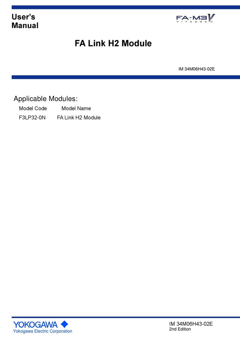
FA-M3
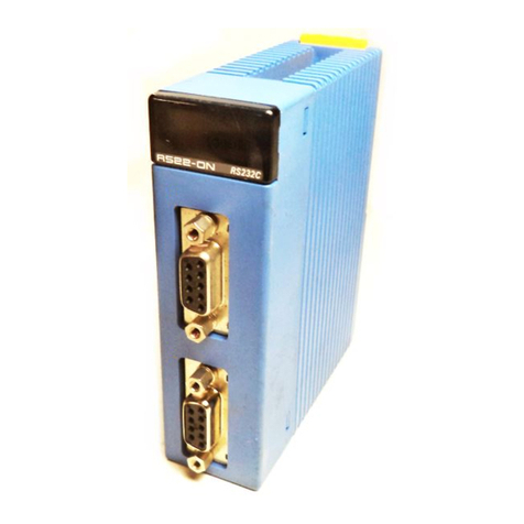
DeviceNet Scanner Module
IM 34M6H28-01E 1st Edition
◆Important ...................................................................................................... ii
◆Introduction................................................................................................ viii
1. Overview .................................................................................................. 1-1
2. Overview of DeviceNet .............................................................................. 2-1
2.1 Network Configuration....................................................................................... 2-1
2.2 I/O Communications (I/O Slave Message) ......................................................... 2-3
2.3 Message Communications (Explicit Peer-to-Peer Message) ............................. 2-4
3. Preparations for Operation ........................................................................ 3-1
4. Module Specifications ............................................................................... 4-1
4.1 Function Specifications ..................................................................................... 4-1
4.2 Operating Environment ..................................................................................... 4-3
4.3 Model and Suffix Codes .................................................................................... 4-3
4.4 Components ..................................................................................................... 4-3
4.5 Display Panel .................................................................................................... 4-4
4.6 Setting Switches ............................................................................................... 4-5
4.6.1 Node Address Setting Switch............................................................ 4-5
4.6.2 Operation Mode Setting Switch......................................................... 4-5
4.6.3 Terminating Resistor Setting Switch .................................................. 4-6
4.7 External Dimensions ......................................................................................... 4-7
5. Attaching and Wiring ................................................................................. 5-1
5.1 Attaching and Detaching a Module .................................................................... 5-1
5.2 External Wiring.................................................................................................. 5-3
6. Module Access ......................................................................................... 6-1
6.1 I/O Relay ........................................................................................................... 6-1
6.2 I/O Data Register .............................................................................................. 6-2
6.3 Access from the CPU Module ........................................................................... 6-4
6.3.1 Access Using Ladder Sequence ....................................................... 6-4
6.3.2 Access Using BASIC ........................................................................ 6-5
7. I/O Communications ................................................................................. 7-1
7.1 Scan List ........................................................................................................... 7-1
7.2 Module Operation ............................................................................................. 7-4
7.3 Transmission Time Intervals ............................................................................ 7-10
7.4 I/O Response Time ......................................................................................... 7-11