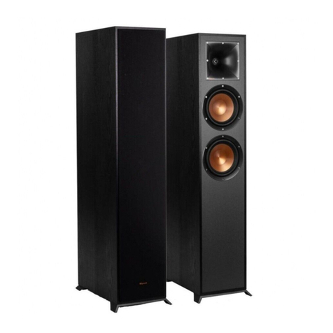
Advanced Native Technologies GREENHEAD 10 User manual

EN USER MANUAL | Section 1
IT MANUALE D’USO | Sezione 1
2-WAY ACTIVE LOUDSPEAKER SYSTEMS & POWERED SUBWOOFERS
DIFFUSORI BI-AMPLIFICATI IN LEGNO & SUBWOOFER ATTIVI

ENGLISH
GREENHEAD Series | User manual
2
3
User manual | GREENHEAD Series
CONTENTS
1| Introduction 3
2| Installation 3
3| Description 4
3.1 | Speakers controls & connections 4
3.2 | Subwoofer controls & connections 6
3.3 | Power supply 8
4| Troubleshooting 9
5| Technical specications 10
6| Notes 22
The warnings in this manual must be observed together with the
“User manual - Section 2”.
PACKAGE CONTENT
• 1x Fullrange Active Speaker - Mod. 10-12-15
• 1x Active Subwoofer - Mod. 15S-18S
• 1x Mains cable with VDE plug
• 1x User manual - Section 1
• 1x User manual - Section 2
1| INTRODUCTION
Thank you for choosing a A.N.T - Advanced Native Technologies - product!
In GREENHEAD series of speaker we have put our passion and our
technological background gained over the years, to offer products that
meet your needs, maintaining the quality over time.
All models in this series provide an extended frequency response with
a clean, undistorted sound even at very high volumes. Specifically
designed for an immediate and user-friendly application, meeting
the needs of those who are looking for an audio system delivering
excellent performances, high connection versatility as well as the best
value in its category.
Please, dedicate some minutes to read this instruction manual in order
to quickly achieve the best performances from this product.
For safety precautions, warranty and disposal, please refer to attached
Section 2.
For further information about all A.N.T products catalog, please visit our
website:
www.ant-sound.com
2| INSTALLATION
GREENHEAD models are provided of:
A| Integrated side and upper handles
B| Lower hole for speaker ole mounting
C| Upper hole for speakers support pole insert
NEVER USE HANDLES TO
SUSPEND THE SPEAKER!
A B
C

ENGLISH
GREENHEAD Series | User manual
4
5
User manual | GREENHEAD Series
5AUX IN STEREO
Unbalanced 3.5mm stereo input plug for any external device
(smartphone, tablet, pc, ecc).
6 L/R
Unbalanced inputs with two RCA plugs for external devices like CD,
DVD player and MIXER.
7MASTER VOL
Speaker master control. Turn the knob clockwise to increase volume, or
counterclockwise to decrease it.
8SIG/CLIP
Led lit green: input signal present.
Led lit red: Indicates the activation of the internal limiter circuit preventing
case, reduce the MASTER level and that of the sound source.
9ON
This LED is lit when the unit is plugged to mains, and the power switch
is ON.
10 GND
Press this switch to reduce or eliminate the noise of the electric ground
whenconnecting signal lines between multipledevices.It is very effective
in eliminating ground loops, but the actual result depends also on other
connected devices.
11 LINE OUTPUT
This XLR-M output provides a balanced line-level signal with the mix of
inputs, before the MASTER control.
It is useful for connection to an audio system or to another active speaker.
3.1 | SPEAKERS CONTROLS & CONNECTIONS
1MIC LEVEL
This knob adjusts the microphone channel level. Turn the knob clockwise to
increase volume, or counterclockwise to decrease it.
2MIC INPUT
Balanced Combo - XLR/6.35 mm. jack - microphone input
You may also use an unbalanced microphone cable.
3LINE/AUX LEVEL
TThis knob adjusts the Line/Aux channel level. Turn the knob clockwise to
increase volume, or counterclockwise to decrease it.
4LINE INPUT
Balanced combo - XLR/6.35 mm. jack - line input.
You may also use an unbalanced cable.
3| DESCRIPTION
5
1
4 116
3 7 8 9 10
2

ENGLISH
GREENHEAD Series | User manual
6
7
User manual | GREENHEAD Series
3.2 | SUBWOOFER CONTROLS & CONNECTIONS
24
7 8
9
10
1 5 63
2 ON
This LED is lit when the unit is plugged to mains, and the power switch
is ON.
3 VOLUME
Subwoofer master control. Turn the knob clockwise to increase volume,
or counterclockwise to decrease it.
4 GND
Press this switch to reduce or eliminate the noise of the electric ground
whenconnecting signal lines between multipledevices.It is very effective
in eliminating ground loops, but the actual result depends also on other
connected devices.
5 LOW CUT
When it is activated, use the OUT L/R to connect two additional active
speakers.
6 PHASE
compensate possible phase cancellations due to venue acoustics, the
presence of multiple subwoofers, or when using not-standard phased
satellites.
7 LEFT/MONO INPUT
Balanced combo - XLR/6.35 mm. jack - line input .You may also use an
unbalanced cable.
8 RIGHT INPUT
Balanced XLR-F line level input. You may also use an unbalanced cable.
9 LINK L/R
Balanced Left/Right channels XLR-M line outputs for parallel wiring of
further active speakers.
10 OUT L/R
Balanced Left/Right channels XLR-M line outputs.
Use these outputs to connect further active speakers, whose signal is
1 SIG/CLIP
Led lit green: input signal present.
distortion and protecting the speakers against overloads. In this case, reduce the
MASTER level and that of the sound source.

ENGLISH
GREENHEAD Series | User manual
8
9
User manual | GREENHEAD Series
1 POWER ON/OFF
Use this switch to turn On/Off the unit.
2 FUSE
Protection fuse.
Caution: Replace the fuse only with one of the same type and with the same
3 MAINS INPUT
Insert in this socket the provided mains cable. Please, be sure the device is switched
off before connecting the cable to the mains. For your safety, never disconnect the
earth lead.
WARNING!
Never remove the product’s front protection mesh. In order to prevent electric
protection mesh (which must be carried out by a service center), disconnect
the power supply immediately.
CAUTION: To reduce the risk of electric shock, do not connect the appliance
to the power supply while the mesh is removed.
4| TROUBLESHOOTING
PROBLEM LEDS SOLUTION
No sound or very low
sound level
Power LED
turned off
Make sure the device is properly
connected to the mains outlet
Power LED turned on,
but low MASTER VOL. Raise MASTER VOL level
Power LED turned on,
MASTER VOL raised, but
input channel LEVEL low.
Check the connections between
sound sources and inputs.
Raise channels LEVEL.
Distortion Clip LED on
Lower the level of MIC and LINE
inputs and/or MASTER level.
Make sure that you haven’t
connected a line signal in
MIC IN input
Confused sound
Make sure you haven’t
simultaneously activated more
sound sources
3.3 | POWER SUPPLY SECTION
123

ENGLISH
GREENHEAD Series | User manual
10
11
User manual | GREENHEAD Series
5| TECHNICALSPECIFICATIONS
GREENHEAD 10 GREENHEAD 12 GREENHEAD 15
System type 2-way vented box 2-way vented box 2-way vented box
LF
speaker - 2” V.C
speaker - 2” V.C
speaker - 2” V.C
Coverage O x V
Class D Class D Class D
Frequency response
SPL - MAX
I/O Connectors
MIC: Combo XLR-F +
AUX IN: 2 x RCA jack,
3,5mm mini-jack
LINE OUT: XLR-M
MIC: Combo XLR-F +
AUX IN: 2 x RCA jack,
3,5mm mini-jack
LINE OUT: XLR-M
MIC: Combo XLR-F +
AUX IN: 2 x RCA jack,
3,5mm mini-jack
LINE OUT: XLR-M
Controls
MIC LEVEL,
LINE/AUX LEVEL,
MASTER VOLUME,
GND switches
MIC LEVEL,
LINE/AUX LEVEL,
MASTER VOLUME,
GND switches
MIC LEVEL,
LINE/AUX LEVEL,
MASTER VOLUME,
GND switches
Power Supply
Fuse
Cabinet material
Weight
GREENHEAD 15S GREENHEAD 18S
System type Vented box Vented box
Driver
Class D Class D
Frequency response
SPL – MAX
I/O Connectors
LINE IN LEFT/MONO:
LINE OUT: 2 x XLR-M
LINE IN LEFT/MONO:
LINE OUT: 2 x XLR-M
Controls
VOLUME knob
GND LIFT, LOW CUT,
VOLUME knob
GND LIFT, LOW CUT,
Power Supply
Fuse
Cabinet material
Weight
EMI CLASSIFICATION

ITALIANO
Serie GREENHEAD | Manuale d’uso
12
13
Manuale d’uso | Serie GREENHEAD
ITALIANO
12
congiuntamente al “Manuale d’uso - Sezione 2”.
CONTENUTO DELL’IMBALLO
• 1x Diffusore Fullrange Attivo - Mod. 10-12-15
• 1x Subwoofer Attivo - Mod. 15S-18S
• 1x cavo di alimentazione (VDE)
• 1x Manuale d’uso - Sezione 1
• 1x Manuale d’uso - Sezione 2
1| INTRODUZIONE
A.N.T - Advanced Native Technologies!
Nei diffusori acustici della serie GREENHEAD abbiamo profuso la nostra
passione ed il nostro know-how maturato nel corso degli anni per offrirvi un
taledaottenererapidamenteilmassimodelleperformancedaquestoprodotto.
A.N.T consultate il
nostro sito: www.ant-sound.com
2| INSTALLAZIONE
I modelli GREENHEAD sono forniti di:
A| Maniglie laterali e superiori integrate.
B| Flangia inferiore per il montaggio del diffusore su stand
C| Flangia superiore per l’inserimento del palo di sostegno ai diffusori.
INDICE
1| Introduzione 13
2| Installazione 13
3| Descrizione 14
3.1 | Connessioni & controlli dei diffusori 14
3.2 | Connessioni & controlli dei subwoofer 16
3.3 | Alimentazione 18
4| Soluzione dei problemi 19
5| Speciche tecniche 20
6| Note 22
A B
C
NON USATE LE MANIGLIE PER
SOSPENDERE I DIFFUSORI!

ITALIANO
Serie GREENHEAD | Manuale d’uso
14
15
Manuale d’uso | Serie GREENHEAD
3| DESCRIZIONE 5 AUX IN STEREO
Ingresso sbilanciato con presa stereo da 3.5mm per qualsiasi dispositivo
esterno (smartphone, tablet, pc, ecc).
6 L/R
Ingressi sbilanciati con due prese RCA per dispositivi esterni come lettori
CD, DVD, MIXER.
7 MASTER VOL
Controllo generale di volume del diffusore. Ruotatelo verso destra per
8 SIG/CLIP
Led verde: segnale in ingresso presente.
Led rosso: indica l’intervento del circuito limitatore interno, che evita
sovraccarichi. In questo caso riducete il segnale MASTER e quello della
sorgente sonora.
9 ON
Questo led si accende quando l’apparecchio è collegato alla rete elettrica
e l’interruttore di accensione è commutato su ON.
10 GND
Premete questo interruttore per ridurre o eliminare il rumore della massa
elettrica quando collegate linee di segnale fra più apparecchi. È molto
anche dagli altri dispositivi collegati.
11 LINE OUTPUT
Questa uscita XLR-M fornisce un segnale bilanciato di livello linea con
il mix degli ingressi prelevato prima del controllo MASTER. È utile per il
collegamento ad un impianto audio o ad un altro diffusore attivo.
3.1 | CONNESSIONI & CONTROLLI DEI DIFFUSORI
1 MIC LEVEL
Questa manopola regola il livello del canale microfonico, ruotatela verso destra per
2 MIC INPUT
Ingresso microfono bilanciato Combo XLR/Jack da 6.35 mm. È possibile usare
anche un cavo microfonico sbilanciato.
3 LINE/AUX LEVEL
Questa manopola regola il livello del canale di linea/Aux, ruotatela verso destra per
4 LINE INPUT
Ingresso di linea bilanciato Combo XLR/Jack da 6.35 mm. È possibile usare anche
un cavo non bilanciato.
5
1
4 116
3 7 8 9 10
2

ITALIANO
Serie GREENHEAD | Manuale d’uso
16
17
Manuale d’uso | Serie GREENHEAD
2 ON
Questo led si accende quando l’apparecchio è collegato alla rete elettrica
e l’interruttore di accensione è commutato su ON.
3 VOLUME
Controllo generale di volume del subwoofer. Ruotatelo verso destra per
4 GND
Premete questo interruttore per ridurre o eliminare il rumore della massa
elettrica quando collegate linee di segnale fra più apparecchi. È molto
anche dagli altri dispositivi collegati.
5 LOW CUT
diffusori attivi supplementari.
6 PHASE
satelliti con fase non standard.
7 LEFT/MONO INPUT
Ingresso di linea bilanciato combo XLR/Jack da 6.35 mm. È possibile
usare anche un cavo sbilanciato.
8 RIGHT INPUT
Ingresso di linea bilanciato XLR-F. È possibile usare anche un cavo
sbilanciato.
9 LINK L/R
Uscite di linea bilanciate XLR-M per i canali Left/Right e il collegamento
10 OUT L/R
uscite per collegare dei diffusori attivi supplementari il cui segnale è
1 SIG/CLIP
Led verde: segnale in ingresso presente
Led rosso: indica l’intervento del circuito limitatore interno, che evita la distorsione
riducete il segnale MASTER e quello della sorgente sonora.
24
7 8
9
10
1 5 63
3.2 | CONNESSIONI & CONTROLLI DEI SUBWOOFER

ITALIANO
Serie GREENHEAD | Manuale d’uso
18
19
Manuale d’uso | Serie GREENHEAD
3.3 | ALIMENTAZIONE 4 | SOLUZIONE DEI PROBLEMI
PROBLEMA SPIE SOLUZIONE
suono troppo basso
Led Power
spento
Assicuratevi che
l’apparecchio sia collegato
correttamente alla presa di
corrente.
LED Power acceso
a MASTER VOL
abbassato
LED Power acceso,
ma LEVEL dei canali
di ingresso abbassati.
Controllate i collegamenti tra
le sorgenti e gli ingressi.
Distorsione Led CLIP
acceso
Attenuate il livello degli
ingressi MIC, LINE e/o
del MASTER
Assicuratevi di non aver
collegato un segnale di linea
nell’ingresso MIC IN
Suono confuso
Assicuratevi di
non aver attivato
contemporaneamente
più sorgenti
123
1 POWER ON/OFF
Interruttore per accensione e lo spegnimento dell’apparecchio.
2 FUSE
Attenzione: Sostituire il fusibile unicamente con uno dello stesso tipo
e con gli stessi valori. Se il fusibile continua a saltare, rivolgetevi ad
3 MAINS INPUT
ATTENZIONE!
il pericolo di scossa elettrica, in caso di danneggiamento accidentale o
ATTENZIONE: Per ridurre il rischio di scosse elettriche, non connettere mai
l’alimentazione di rete all’apparecchio mentre la griglia è rimossa.

ITALIANO
Serie GREENHEAD | Manuale d’uso
20
21
Manuale d’uso | Serie GREENHEAD
5 | SPECIFICHE TECNICHE
GREENHEAD 10 GREENHEAD 12 GREENHEAD 15
Sistema 2-vie bass reflex 2-vie bass reflex 2-vie bass reflex
LF Altoparlante custom in
Altoparlante custom in
Altoparlante custom in
Driver a compressione
Driver a compressione
Driver a compressione
Copertura
Classe D Classe D Classe D
Risposta
SPL - MAX
Connettori I/O
MIC: Combo XLR-F +
jack 6,35mm
LINE IN: Combo XLR-F
+ jack 6,35mm
AUX IN: 2 x RCA jack,
mini-jack 3,5mm
LINE OUT: XLR-M
MIC: Combo XLR-F +
jack 6,35mm
LINE IN: Combo XLR-F
+ jack 6,35mm
AUX IN: 2 x RCA jack,
mini-jack 3,5mm
LINE OUT: XLR-M
MIC: Combo XLR-F +
jack 6,35mm
LINE IN: Combo XLR-F
+ jack 6,35mm
AUX IN: 2 x RCA jack,
mini-jack 3,5mm
LINE OUT: XLR-M
Controlli
MIC LEVEL,
LINE/AUX LEVEL,
MASTER VOLUME,
Interruttore GND
MIC LEVEL,
LINE/AUX LEVEL,
MASTER VOLUME,
Interruttore GND
MIC LEVEL,
LINE/AUX LEVEL,
MASTER VOLUME,
Interruttore GND
Fusibile
Materiale cabinet
Dimensioni (LxAxP)
Peso
GREENHEAD 15S GREENHEAD 18S
Sistema Bass reflex Bass reflex
Altoparlante
Classe D Classe D
Risposta
SPL – MAX
Connettori I/O
LINE IN LEFT/MONO:
LINE OUT: 2 x XLR-M
LINE IN LEFT/MONO:
LINE OUT: 2 x XLR-M
Controlli
Manopola VOLUME
Interruttori GND LIFT,
Manopola VOLUME
Interruttori GND LIFT,
Fusibile
Materiale cabinet
Dimensioni (LxAxP)
Peso
CLASSIFICAZIONE EMI

22
Manuale d’uso | Serie GREENHEAD
6 | NOTES/NOTE
www.ant-sound.com
ENG The information contained in this manual have been carefully drawn up and checked.
However no responsibility will be assumed for any incorrectness. This manual cannot cover all
the possible contingencies which may arise during the product installation and use. Should
further information be desired, please contact us or our local distributor. A.E.B. Industriale Srl
can not be considered responsible for damages which may be caused to people and things
when using this product. Specications and features are subject to change without prior notice.
ITA Le informazioni contenute in questo manuale sono state attentamente redatte e
controllate. Tuttavia non si assume alcuna responsabilità per eventuali inesattezze. Questo
manuale non può contenere una risposta a tutti i singoli problemi che possono presentarsi
durante l’installazione e l’uso dell’apparecchio. Siamo a vostra disposizione per fornirvi
eventuali ulteriori informazioni e consigli. A.E.B. Industriale Srl non può essere ritenuta
responsabile per danni o incidenti a cose o persone, causati o connessi all’utilizzazione o
malfunzionamento dell’apparecchio.
Made in China
Prodotto in Cina

A.E.B. Industriale Srl -
This manual suits for next models
5
Table of contents
Languages:
Other Advanced Native Technologies Speakers manuals
Advanced Native Technologies
Advanced Native Technologies B-TWIG 8 Mobile User manual
Advanced Native Technologies
Advanced Native Technologies ASM 10 User manual
Advanced Native Technologies
Advanced Native Technologies BBM 3 User manual
Advanced Native Technologies
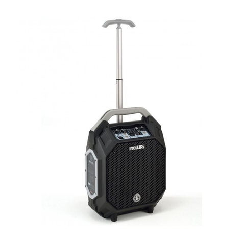
Advanced Native Technologies iROLLER 8 User manual

