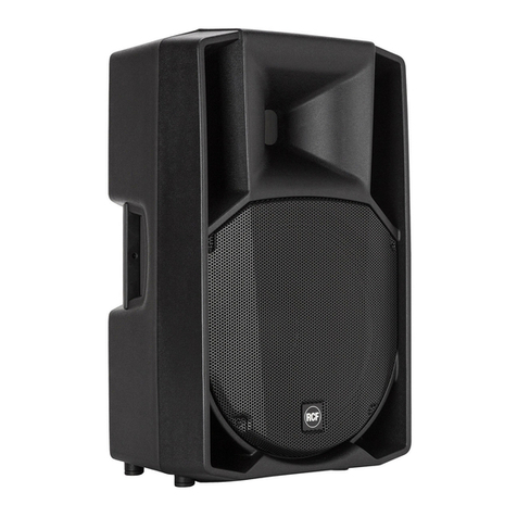
Advanced Native Technologies ASM 10 User manual

ACTIVE COAXIAL STAGE MONITORS
MONITOR DA PALCO ATTIVI COASSIALI
MONITEURS DE SCÈNE ACTIFS COAXIAUX
AKTIVE KOAXIAL-BÜHNENMONITORE
MONITORES ACTIVOS COAXIALES DE ESCENARIO
ASM 10 | ASM 12 | ASM 15
EN USER MANUAL | SECTION 1
IT MANUALE D’USO | SEZIONE 1
FR NOTICE D’EMPLOI | SECTION 1
DE BEDIENUNGSANLEITUNG | KAPITEL 1
ES MANUAL DE USO | SECCIÓN 1

ENGLISH
ASM Series | User manual
2
3
User manual | ASM Series
TABLE OF CONTENTS
1| Introduction 3
2| Installation 4
3| Description 5
3.1 | Inputs & controls 5
3.2 | Power supply 8
4| Troubleshooting 9
5| Technical specications 10
6| Notes 52
The warnings in this manual must be observed together with the
“USER MANUAL - SECTION 2”.
CONTENUTO DELL’IMBALLO
• 1 x active coaxial stage monitor
- n.1 mains cord (VDE)
• 1x User manual - Section 1
• 1x User manual - Section 2
1| INTRODUCTION
Thank you for choosing a A.N.T - Advanced Native Technologies
- product!
Inthisprofessionalcoaxialspeakerweputourpassionandourtechnological
background gained over the years, to offer products that meet your needs,
maintaining the quality over time.
Specically designed for an immediate and user-friendly application, meeting
the needs of those who are looking for an audio system delivering excellent
performances, high connection versatility as well as the best value in its
category.
• Selectable MIC/LINE inputs for better signal management upon different
usage scenarios;
• Wide versatility of use, with the choice between two installation positions
as a stage monitor or as a PA speaker mounted on a tripod;
• Immediate conguration, thanks to the equalization presets that can be
set from the side panel.
Optional covers are available to facilitate transport, assembly and product
integrity.
Please, dedicate some minutes to read this instruction manual in order to
quickly achieve the best performances from this product.
For safety precautions, warranty and disposal, please refer to attached
Section 2.
For further information about all A.N.T products catalog, please visit our
website: www.ant-intomusic.com.

ENGLISH
ASM Series | User manual
4
5
User manual | ASM Series
2| INSTALLATION
Each speaker is equipped with:
A| Recessed side handles
B| Ø 35mm. flange for pole mounting
C| Non-slip rubber feet
D| Front metal protection grille
.
For speaker installation and to guarantee its correct performance, strictly follow the
instructions below:
• Place the speaker in a horizontal position on a flat and stable surface, making sure
that all the lower rubber feet are perfectly adhering to the floor or to the supporting
surface. The speaker is designed for use on the floor (wedge monitor conguration).
• Never install the speaker on mobile carts, chairs, tables or similar objects that are
not stable or unable to withstand the weight.
• To allow for proper heat dissipation of the amplication, leave sufcient distance
between the rear panel of the speaker andother objects such as walls, corners, curtains,
and never place the appliance near sources of heat of any kind.
• When used outdoors, avoid places exposed to bad weather.
CAUTION:Installthespeakerinastableandsafeway,soastoavoidanydangerous
condition for the safety of people and structures.
A A
C
CB
D
3| DESCRIPTION
3.1 | INPUTS & CONTROLS
1 LINE INPUT L/R
Balanced line level inputs, with COMBO (XLR-F + 6,35mm. socket)
connectors. You can also use an unbalanced mic cable. The inputs level
is adjusted by LEVEL knob.
NOTE: Please try to always use balanced cables.
2 LINE / MIC BUTTON
Place the button on LINE (up) to use a line level source (mixer and pre-
amplied devices) or MIC (pressed) for using a microphone. To lower
or raise it, use a screwdriver with a small flat head.
3 LINK OUT
Link output of input signal on XLR-M plug. The signal of this output
depends on the setting of the LEVEL knob.
4 LIVE MONITOR / PLAYBACK BUTTON
Press this button to select the optimal equalization for using the speaker.
It is possible to select the equalization setting between two different
presets:
3
4
2
1

ENGLISH
ASM Series | User manual
6
7
User manual | ASM Series
LIVE MONITOR
Perfect for live performances with the speaker positioned onthe ground as a wedge
stage monitor. Suitable for musicians and singers.
PLAYBACK
It emphasizes the low and high frequencies, and is ideal for listening and using
reproduced music (MP3 players, CDs etc.), both for use as a main system mounted
on a tripod but also as a reinforcement monitor.
5 LEVEL
Thiscontroladjusts thespeakeroutputvolume.Turntheknobclockwisetoincrease
thevolumeor counterclockwisetolowerit.Foroptimal adjustment alwaysconsider
the acoustics of the environment and the musical genre.
6 INDICATORS ON & SIG / CLIP
Led ON: the unit is powered.
SIG/CLIPGreenLED: the signal is present in the MIC/LINE INPUT channel. In normal
operation the LED acts as a Vu meter indicating the audio level.
SIG/CLIP Red LED: the input signal is very high and is close to distortion.
If the red LED lights up continuously, it’s necessary to reduce the LEVEL level or
reduce the levels of the devices connected to the MIC / LINE INPUT input.
CAUTION: the unit must never work with levels causing the SIG/CLIP LED to flash
red almost constantly.
7 REAR PANEL
The cooling process of the amplier and temperature control within laws limits
are ensured by proper ventilation of the system, thus it’s recommended to don’t
obstruct or cover in any way the rear panel of the speaker.
6
5
8 RECESSED HANDLES FOR LIFTING AND TRANSPORT
Use these recessed handles (Fig.1) for transporting and positioning the
speaker. Do not use them to hang the speaker or to lock it in any position.
7
8
Fig.1 – Recessed handles for transport

ENGLISH
ASM Series | User manual
8
9
User manual | ASM Series
3.2 | POWER SUPPLY
1 AC VOLTAGE SELECTOR
Operating voltage selector. Generally it is not necessary to act on this command
since it is set at the factory.
WARNING! Before switching on the unit, make sure that the mains voltage and
that of the device match.
2 POWER ON/OFF
Use this switch to turn ON/OFF the system.
NOTE: For proper operation always switch on the system last and switch it off rst.
Before turning on the system, make sure the LEVEL knob is at minimum.
3 FUSE
Protection fuse.
CAUTION: Replace the fuse only with one of the same type and with the same
values. If the fuse blows repeatedly, contact an authorized service center.
4 MAINS INPUT
IEC mains socket with integrated EMI lter. Each package is supplied with the
necessary power cord, specic for your area. Insert the mains cable into this
socket, but make sure the unit is switched off before connecting the cable to the
mains. For your safety, never disconnect the ground lead..
CAUTION: To reduce the risk of electric shock, never connect the power supply
to the appliance while the grille is removed.
1
2
3
4
4 | TROUBLESHOOTING
PROBLEM LED SOLUTION
No sound Power LED turned
off.
Make sure the system is properly
connected to the mains outlet.
Make sure that mains plug is rmly
inserted into the socket.
very low sound level
Power LED turned
on, but low MAIN
LEVEL.
Turn the MAIN LEVEL knob
clockwise.
Make sure the SIG LED is on.
Check the signal cable.
Distortion SIG/CLIP LED
lit red
Lower the level of LEVEL knob or
input sources. When using input line
signals, make sure that the LINE /
MIC button is not pressed in the MIC
position.
ON/LIMIT LED lit
green Check the source level.
Booming sound
Put the selector in
LIVE MONITOR position
Check source signal.
Harsh sound
Put the selector in
PLAYBACK position
Check source signal.

ENGLISH
ASM Series | User manual
10
11
User manual | ASM Series 10
5| TECHNICAL SPECIFICATIONS
ASM10 ASM12 ASM15
System 2-way vented box 2-way vented box 2-way vented box
LF Custom 10” Woofer,
2” VC
Custom 12” Woofer,
2.5” VC
Custom 15” Woofer,
3” VC
HF 1” compression driver,
1” VC
1” compression driver,
1.35” VC
1” compression driver,
1.35” VC
Amplication Class-D + Class-A/B Class-D + Class-A/B Class-D + Class-A/B
Peak power (LF+HF) 400W 600W 600W
Frequency response
(+/-10dB)
70Hz-20kHz 65Hz-20kHz 55Hz-20kHz
MAX SPL 122dB 124dB 126dB
DSP 56Bit 56Bit 56Bit
AD/DA conversion 24Bit / 48kHz 24Bit / 48kHz 24Bit / 48kHz
EQ 2 Presets 2 Presets 2 Presets
Input and output
connectors
MIC/LINE COMBO
(XLR-F + 2 x jack
6.35mm. 1/4”)
LINK output: XLR-M
MIC/LINE COMBO
(XLR-F + 2 x jack
6.35mm. 1/4”)
LINK output: XLR-M
MIC/LINE COMBO
(XLR-F + 2 x jack
6.35mm. 1/4”)
LINK output: XLR-M
Controls LEVEL,
LINE/MIC switch
ON-PEAK/SIGN LEDs
PRESET button
LEVEL,
LINE/MIC switch
ON-PEAK/SIGN LEDs
PRESET button
LEVEL,
LINE/MIC switch
ON-PEAK/SIGN LEDs
PRESET button
ASM10 ASM12 ASM15
Operating mains
Fuse
220-240V~
50-60Hz
T2A L 250V~
110-120V~
50-60Hz
T4A L 250V~
220-240V~
50-60Hz
T2A L 250V~
110-120V~
50-60Hz - T4A L
250V~
220-240V~
50-60Hz
T2A L 250V~
110-120V~
50-60Hz
T4A L 250V~
Max power
consumption
300 W 300 W 300 W
Cabinet 2 recessed handles
Pole mount
Ø 35mm. hole
2 recessed handles
Pole mount
Ø 35mm. hole
2 recessed handles
Pole mount
Ø 35mm. hole
Cabinet material 15mm plywood 15mm plywood 15mm plywood
Cabinets nishing Anti-scratch
paint with high
mechanical
resistance
Anti-scratch
paint with high
mechanical
resistance
Anti-scratch
paint with high
mechanical
resistance
Dimensions
(W x H x D)
380 x 333 x 480
mm
450 x 338 x 510
mm
495 x 405 x 610
mm
Net weight 12 Kg. 19 Kg. 20.5 Kg.
Optional accessories CV-SM10
padded cover
CV-SM12
padded cover
CV-SM15
padded cover

12
13
ITALIANO
Serie ASM | Manuale d’uso
Manuale d’uso | Serie ASM
INDICE
1| Introduzione 13
2| Installazione 14
3| Descrizione 15
3.1 | Ingressi & controlli 15
3.2 | Alimentazione 18
4| Soluzione dei problemi 19
5| Speciche tecniche 20
6| Note 52
Le avvertenze del presente manuale devono essere osservate congiuntamente al
“MANUALE D’USO - SEZIONE 2”.
1| INTRODUZIONE
GrazieperaveracquistatounprodottoA.N.T-AdvancedNativeTechnologies!
In questo diffusore coassiale professionale abbiamo profuso la nostra
passione ed il nostro know-how maturato nel corso degli anni per offrirvi un
prodotto che soddis le vostre esigenze e mantenga la sua qualità nel tempo.
Progettato appositamente per un utilizzo estremamente immediato e
semplice, risponde alle esigenze di quanti desiderano un monitor da palco
attivo in grado di fornire ottime prestazioni e il miglior rapporto qualità/prezzo
possibile nella sua categoria.
Caratterizzato da un look elegante e contemporaneo, coniuga in maniera
ottimale caratteristiche professionali di grande qualità ed eccezionale
valore quali:
• Ingressi selezionabili MIC/LINE per una la miglior gestione del segnale
in base agli scenari di utilizzo;
• Ampia versatilità di utilizzo, con la scelta fra due posizioni di installazione
come monitor da palco oppure l’uso come diffusore di amplicazione, montato
su treppiede;
• Immediata congurabilità, grazie ai preset di equalizzazione impostabili
dal pannello laterale.
Sono disponibili le coperture opzionali nalizzate a facilitare il trasporto, il
montaggio e l’integrità del prodotto.
Ritagliatevi qualche minuto per leggere questo manuale di istruzioni in
modo tale da ottenere rapidamente il massimo delle performance da
questo prodotto.
Perleistruzionirelativeasicurezza,leprecauzioni,lagaranziaelosmaltimento
fate riferimento all’allegato sezione 2.
Per ulteriori informazioni su tutti i prodotti del catalogo A.N.T consultate il
nostro sito: www.ant-intomusic.com.
CONTENUTO DELL’IMBALLO
• 1 x Monitor coassiale attivo
- n.1 cavo di alimentazione (VDE)
• 1x Manuale d’uso - Sezione 1
• 1x Manuale d’uso - Sezione 2

14
15
ITALIANO
Serie ASM | Manuale d’uso
Manuale d’uso | Serie ASM
2| INSTALLAZIONE
Ogni diffusore è dotato di:
A| Maniglie laterali incassate
B| Flangia con foro Ø 35mm. per palo
C| Piedini antiscivolo in gomma
D| Griglia frontale metallica di protezione
Per l’installazione del diffusore e a garanzia del suo corretto funzionamento, attenetevi
scrupolosamente alle seguenti istruzioni:
• Collocate il diffusore in posizione orizzontale su una supercie piana e stabile,
assicurandovi che tutti i piedini inferiori in gomma siano perfettamente aderenti al
pavimento o alla supercie di appoggio. Il diffusore è predisposto per l’utilizzo su
pavimento (congurazione monitor).
• Non installate mai il diffusore su carrelli mobili, sedie, tavoli o oggetti simili che non
siano stabili o non in grado di sopportare il peso.
• Per consentire una corretta dissipazione del calore dell’amplicazione, lasciate
una distanza sufciente tra il panello posteriore del diffusore e altri oggetti quali
pareti, angoli, tende, e non collocate mai l’apparecchio vicino a sorgenti di calore
di qualsiasi tipo.
• Nell’utilizzo all’aperto evitate luoghi esposti alle intemperie.
ATTENZIONE: Installate il diffusore in modo stabile e sicuro, in modo tale da
evitare qualsiasi condizione di pericolo per l’incolumità di persone e strutture.
3| DESCRIZIONE
3.1 | INGRESSI & CONTROLLI
1 MIC/LINE INPUT
Ingresso microfono bilanciato con presa Combo XLR-F/jack da 6,35
mm. È possibile usare anche un cavo microfonico jack non bilanciato.
Il volume di questi ingressi è regolato tramite la manopola LEVEL.
NOTA: Usate possibilmente sempre cavi bilanciati.
2 TASTO LINE/MIC
Posizionate il tasto su LINE (alzato) per l’utilizzo di una sorgente a livello
linea (mixer e dispositivi pre-amplicati) o su MIC (premuto) per l’utilizzo
di un microfono. Per abbassarlo o alzarlo utilizzate un cacciavite con
una punta piccola.
3 LINK OUT
Uscita di rilancio del segnale in ingresso su spina XLR-M. Il segnale di
questa uscita dipende dalla regolazione della manopola LEVEL.
4 TASTO LIVE MONITOR/PLAYBACK
Premete questo tasto per selezionare l’equalizzazione ottimale per
l’utilizzo del diffusore. E’ possibile selezionare l’impostazione di
equalizzazione tra due diversi preset:
3
4
2
1
A A
C
CB
D

16
17
ITALIANO
Serie ASM | Manuale d’uso
Manuale d’uso | Serie ASM
LIVE MONITOR
Ideale per esecuzioni dal vivo con il diffusore posizionato a terra come monitor da
palco. Indicato per musicisti e cantanti.
PLAYBACK
Enfatizza le frequenze basse e alte, ed è ideale per ascolto e utilizzo di musica
riprodotta (lettori MP3, CD etc.), sia per uso come sistema principale montato su
treppiede ma anche come monitor di rinforzo.
5 LEVEL
Questo controllo regola il volume di uscita del diffusore. Girate la manopola in senso
orarioperaumentareilvolumeoinsensoantiorarioperabbassarlo.Perunaregolazione
ottimale considerate sempre l’acustica dell’ambiente e il genere musicale.
6 INDICATORI ON & SIG/CLIP
Led ON: l’unità è alimentata.
Led SIG/CLIP verde: il segnale è presente nel canale MIC/LINE INPUT. Nel normale
funzionamento il led funge da Vu-Meter e indica il livello audio.
LedSIG/CLIProsso:ilsegnaleiningressoèmoltoforteedèprossimoalladistorsione.
ATTENZIONE: l’apparecchio non deve mai lavorare con livelli tali da far illuminare
di rosso in modo pressoché costante il LED SIG/CLIP.
7 PANNELLO POSTERIORE
Il processo di raffreddamento dell’amplicatore e il mantenimento della temperatura
del pannello nei limiti di legge è garantito da una corretta dissipazione del calore,
pertantosiraccomandadinonostruireocoprireinnessunmodoiltelaioeilpannello
posteriore del diffusore.
8 MANIGLIE INCASSATE PER IL SOLLEVAMENTO E IL TRASPORTO
Utilizzate queste maniglie incassate (Fig.1) per il trasporto e il
posizionamento del diffusore. Non usatele per appendere il diffusore o
per bloccarlo in qualsiasi posizione.
6
5
7
8
Fig.1 – Maniglie laterali incassate per trasporto

18
19
ITALIANO
Serie ASM | Manuale d’uso
Manuale d’uso | Serie ASM
3.2 | ALIMENTAZIONE
1 AC VOLTAGE SELECTOR
Selettore della tensione di esercizio. Generalmente non occorre agire su questo
comando poiché è impostato in fabbrica.
ATTENZIONE! Prima di accendere l’apparecchio assicuratevi che la tensione di
rete e quella del dispositivo coincidano.
2 POWER ON/OFF
Interruttore per accensione/spegnimento del diffusore.
NOTA: per un corretto funzionamento accendete sempre il diffusore per ultimo e
spegnetelo per primo. Prima di accendere il sistema assicuratevi che la manopola
LEVEL sia al minimo.
3 FUSE
Fusibile di protezione.
ATTENZIONE: Sostituire il fusibile unicamente con uno dello stesso tipo e con gli
stessi valori. Se il fusibile continua a saltare, rivolgetevi ad un centro di assistenza
autorizzato.
4 MAINS INPUT
Presa IEC di ingresso con ltro di rete integrato. Ogni confezione è fornita del
cavo di alimentazione necessario, specico per la vostra zona. Inserite in questa
presa il cavo per l’alimentazione elettrica ma accertatevi che l’apparecchio sia
spento prima di collegare il cavo alla rete. Per la vostra sicurezza, non scollegate
mai il polo di messa a terra.
ATTENZIONE: Per ridurre il rischio di scosse elettriche, non connettere mai
l’alimentazione di rete all’apparecchio quando la griglia è rimossa.
4 | SOLUZIONE DEI PROBLEMI
PROBLEMA SPIE LUMINOSE SOLUZIONE
Assenza di suono Led ON spento
Assicuratevi che l’apparecchio sia
collegato correttamente alla presa di
corrente elettrica. Accertatevi che la
spina di rete sia saldamente inserita
nella presa.
Suono troppo basso LED ON acceso ma
LEVEL abbassato.
Girate la manopola LEVEL in senso
orario.
Assicuratevi che il LED SIG sia
acceso.
Controllate il cavo di segnale
Distorsione Led SIG/CLIP
rosso
Attenuate il livello di LEVEL o delle
sorgenti in ingresso. Usando segnali
di linea in ingresso assicuratevi che
il tasto LINE/MIC non sia premuto in
posizione MIC.
Led SIG/CLIP
verde Controllate il livello della sorgente.
Suono risonante
Mettete il selettore nella posizione
LIVE MONITOR
Controllate il segnale della sorgente
Suono stridente
Mettete il selettore nella posizione
PLAYBACK
Controllate il segnale della sorgente
1
2
3
4

20
21
ITALIANO
Serie ASM | Manuale d’uso
Manuale d’uso | Serie ASM 20
5| SPECIFICHE TECNICHE
ASM10 ASM12 ASM15
Sistema Bass reflex, 2 vie Bass reflex, 2 vie Bass reflex, 2 vie
LF Woofer custom da 10”,
VC da 2”
Woofer custom da 12”,
VC da 2,5”
Woofer custom da 15”,
VC da 3”
HF Driver a compressione
da 1”, VC da 1”
Driver a compressione
da 1”, VC da 1,35”
Driver a compressione
da 1”, VC da 1,35”
Amplicazione Classe D + classe A/B Classe D + classe A/B Classe D + classe A/B
Potenza di picco
(LF+HF)
400W 600W 600W
Risposta in frequenza
(+/-10dB)
70Hz-20kHz 65Hz-20kHz 55Hz-20kHz
MAX SPL 122dB 124dB 126dB
DSP 56Bit 56Bit 56Bit
Conversione AD/DA 24Bit / 48kHz 24Bit / 48kHz 24Bit / 48kHz
EQ 2 Preset 2 Preset 2 Preset
Connettori per
ingressi e uscite
MIC/LINE: Combo
(XLR-F + jack 6,35mm.)
Uscita Link XLR-M
MIC/LINE: Combo
(XLR-F + jack 6,35mm.)
Uscita Link XLR-M
MIC/LINE: Combo
(XLR-F + jack 6,35mm.)
Uscita Link XLR-M
Controlli LEVEL,
interruttore LINE/MIC
led ON-PEAK/SIGN
tasto PRESET
LEVEL,
interruttore LINE/MIC
led ON-PEAK/SIGN
tasto PRESET
LEVEL,
interruttore LINE/MIC
led ON-PEAK/SIGN
tasto PRESET
ASM10 ASM12 ASM15
Tensione operativa
Fusibile
220-240V~
50-60Hz
T2A L 250V~
110-120V~
50-60Hz
T4A L 250V~
220-240V~
50-60Hz
T2A L 250V~
110-120V~
50-60Hz
T4A L 250V~
220-240V~
50-60Hz
T2A L 250V~
110-120V~
50-60Hz
T4A L 250V~
Max assorbimento 300W 300W 300W
Cabinet 2 maniglie
incassate
Foro per palo
Ø 35mm.
2 maniglie
incassate
Foro per palo
Ø 35mm.
2 maniglie
incassate
Foro per palo
Ø 35mm.
Materiale del cabinet Multistrato da
15mm.
Multistrato da
15mm.
Multistrato da
15mm.
Finitura del cabinet Vernice
anti-grafo con
elevata resistenza
meccanica
Vernice
anti-grafo con
elevata resistenza
meccanica
Vernice
anti-grafo con
elevata resistenza
meccanica
Dimensioni (L x H x P) 380 x 333 x 480
mm
450 x 338 x 510
mm.
495 x 405 x 610
mm.
Peso netto 12Kg 19Kg 20,5Kg
Accessori opzionali Copertura
imbottita CV-SM10
Copertura
imbottita CV-SM12
Copertura
imbottita CV-SM15

22
23
FRANÇAIS
Serie ASM | Notice d’emploi
Notice d’emploi | Serie ASM
TABLE DES MATIÈRES
1| Introduction 23
2| Installation 24
3| Description 25
3.1 | Entrées et contrôles 25
3.2 | Alimentation 28
4| Dépannage 29
5| Spécications techniques 30
6| Notes 52
Respectez impérativement les avertissements ou mises en garde contenus dans la
présente notice ainsi que les indications de la « NOTICE D’EMPLOI - SECTION 2 ».
1| INTRODUCTION
Nous vous remercions d’avoir acheté un produit A.N.T - Advanced Native
Technologies!
Cemoniteur coaxial professionnelestlefruità la foisdenotregrandepassion
pournotremétier et de notreexpériencepluriannuelle. Il a étédéveloppépour
vous offrir un produit répondant à toutes vos exigences et attentes, tout en
maintenant durablement ses performances et sa qualité de haut niveau.
Conçu spéciquement pour une utilisation extrêmement intuitive et simple,
il répond aux besoins de ceux qui cherchent un moniteur de scène actif
capable de fournir d’excellentes performances et le meilleur rapport qualité-
prix possible pour sa catégorie.
Caractérisé par un look élégant et contemporain, il allie de manière optimale
des caractéristiques professionnelles de grande qualité et une valeur
exceptionnelle telle que :
• Entrées MIC/LINE sélectionnables pour une meilleure gestion du signal
en fonction des scénarios d’utilisation ;
• Grande polyvalence d’utilisation, avec le choix entre deux positions
d’installation en tant que moniteur de scène ou en tant qu’enceinte
d’amplication montée sur un trépied ;
• Configurabilité immédiate, grâce aux préréglages d’égalisation
sélectionnés sur le panneau latéral.
Unesérie de housses optionnelles sont disponiblespourfaciliterletransport,
l’assemblage et l’intégrité du produit.
Les quelques instants que vous consacrerez à la lecture de cette notice
d’emploi vous permettront de bien connaître ce produit et par là même de
bénécier pleinement de ses performances.
Pour les consignes de sécurité, les précautions, la garantie et l’élimination,
se référer à la section 2.
Pour d’autres informations sur tous les produits du catalogue A.N.T
rendez-vous sur notre site : www.ant-intomusic.com.
CONTENU DE L’EMBALLAGE
• 1 x Moniteur coaxial actif
- n.1 câble d’alimentation (VDE)
• 1x Notice d’emploi - Section 1
• 1x Notice d’emploi - Section 2

24
25
FRANÇAIS
Serie ASM | Notice d’emploi
Notice d’emploi | Serie ASM
2| INSTALLATION
Chaque enceinte est équipée de :
A| Poignées latérales encastrées
B| Bride avec orice Ø 35mm pour pied
C| Pieds en caoutchouc antidérapant
D| Grille de protection frontale en métal
Respectez scrupuleusement les instructions ci-dessous pour installer l’enceinte et en
garantir le bon fonctionnement :
• Placez l’enceinte en position horizontale sur une surface plane et stable, en vous
assurant que tous les pieds en caoutchouc inférieurs adhèrent parfaitement au
sol ou à la surface du support. L’enceinte est conçue pour une utilisation sur le sol
(conguration moniteur).
• Ne jamais installer l’enceinte sur des chariots mobiles, des chaises, des tables ou
des objets similaires qui ne sont pas stables ou capables de supporter le poids.
• Pour permettre une dissipation correcte de la chaleur de l’amplication, laissez une
distance sufsante entre le panneau arrière de l’enceinte et d’autres objets tels que
les murs, les coins, les rideaux, et ne placez jamais l’appareil à proximité de sources
de chaleur de quelque nature que ce soit.
• En utilisation extérieure, évitez les endroits exposés aux intempéries.
ATTENTION : Installez l’enceinte de manière stable et sûre, de façon à éviter toute
condition dangereuse pour la sécurité des personnes et des structures.
3| DESCRIPTION
3.1 | ENTRÉES & CONTRÔLES
1 MIC/LINE INPUT
Entrée micro symétrique avec prise Combo XLR-F/jack de 6,35 mm. Il
est possible d’utiliser un câble micro jack non symétrique. Le volume
de ces entrées est réglé via le bouton LEVEL.
REMARQUE : Toujours utiliser des câbles symétriques si possible.
2 BOUTON LINE/MIC
Réglez le bouton sélecteur sur LINE (levé) pour utiliser une source au
niveau ligne (table de mixage ou dispositifs pré-ampliés) ou sur MIC
(appuyé) pour une utilisation microphone. Pour abaisser ou relever le
bouton, utilisez un tournevis avec une petite pointe.
3 LINK OUT
Sortie relais du signal en entrée sur prise XLR-M. Le signal de cette
sortie dépend du réglage du bouton LEVEL.
4 BOUTON LIVE MONITOR/PLAYBACK
Appuyez sur ce bouton pour sélectionner l’égalisation optimale pour
l’utilisation de l’enceinte.
Il est possible de sélectionner les paramètres d’égalisation parmi deux
préréglages différents :
3
4
2
1
A A
C
CB
D

26
27
FRANÇAIS
Serie ASM | Notice d’emploi
Notice d’emploi | Serie ASM
LIVE MONITOR
Idéal pour les représentations en direct avec l’enceinte placée au sol en tant que
moniteur de scène. Convient pour les musiciens et les chanteurs.
PLAYBACK
Accentue les basses et les hautes fréquences, idéal pour écouter et utiliser de la
musique reproduite (lecteurs MP3, CD, etc.), comme système principal monté sur
un trépied mais également comme moniteur de renfort.
5 LEVEL
Ce contrôle règle le volume de sortie de l’enceinte. Tournez le bouton dans le sens
des aiguilles d’une montre pour augmenter le volume ou dans le sens contraire
pour l’abaisser. Pour un réglage optimal, tenez toujours compte de l’acoustique de
l’environnement et du genre musical.
6 INDICATEURS ON & SIG/CLIP
Led ON : l’appareil est alimenté.
Led verte SIG/CLIP : le signal est présent dans le canal MIC/LINE INPUT. En
fonctionnement normal, la led agit comme un vumètre et indique le niveau audio.
Led SIG/CLIP rouge : le signal d’entrée est très fort, proche de la distorsion.
Si la led rouge est allumée en permanence, réduire le niveau LEVEL ou réduire les
niveaux des appareils connectés à l’entrée MIC/LINE INPUT.
ATTENTION : l’appareil ne doit jamais fonctionner avec des niveaux entraînant
l’allumage rouge quasi permanent de la led SIG/CLIP.
7 PANNEAU ARRIÈRE
Le processus de refroidissement de l’amplicateur et le maintien de la température
du panneau dans les limites légales sont garantis par une ventilation adéquate de
l’appareil. Il est donc recommandé de ne pas obstruer ou recouvrir le châssis et le
panneau arrière de l’enceinte.
8 POIGNÉES ENCASTRÉES POUR LE LEVAGE ET LE TRANSPORT
Utilisez ces poignées encastrées (Fig.1) pour transporter et positionner
l’enceinte.Nelesutilisez paspouraccrocherl’enceinteoupour labloquer
dans une position quelconque.
6
57
8
Fig.1 – Poignées de transport latérales encastrées

28
29
FRANÇAIS
Serie ASM | Notice d’emploi
Notice d’emploi | Serie ASM
3.2 | ALIMENTATION
1 AC VOLTAGE SELECTOR
Sélecteur de la tension de fonctionnement. En général inutile d’agir sur cette
commande, congurée d’usine.
ATTENTION : Avant de mettre l’appareil en marche, assurez-vous que la tension
du secteur et celle de l’appareil correspondent.
2 POWER ON/OFF
Commutateur d’allumage et extinction de l’enceinte.
REMARQUE:pourunfonctionnementcorrect,allumeztoujoursl’enceinteendernier
et éteignez-la en premier. Avant de mettre le système sous tension, assurez-vous
que le bouton LEVEL est au minimum.
3 FUSE
Fusible de protection.
ATTENTION : Remplacez le fusible uniquement par un fusible du même type et
possédant les mêmes valeurs.
Si le fusible continue à sauter, contactez un centre de service agréé.
4 MAINS INPUT
Prise d’entrée IEC avec ltre de ligne intégré. Chaque emballage contient le
cordon d’alimentation nécessaire, spécique de votre région. Insérez le câble
d’alimentation dans cette prise, mais assurez-vous que l’appareil est éteint avant
de brancher le câble au secteur. Pour votre sécurité, ne débranchez jamais le pôle
de mise à la terre..
ATTENTION : Pour réduire le risque d’électrocution, ne branchez jamais
l’alimentation électrique à l’appareil lorsque la grille est retirée.
4 | DÉPANNAGE
PROBLÈME VOYANTS LUMINEUX SOLUTION
Absence de son LED ON éteinte.
Assurez-vous que l’appareil est
branché correctement à la prise
de courant. Assurez-vous que
la che secteur est fermement
insérée dans la prise.
Son trop bas LED ON allumée mais
LEVEL abaissé
Tournez le bouton LEVEL dans le
sens des aiguilles d'une montre.
Assurez-vous que la led SIG est
allumée.
Vériez le câble de signal
Distorsion Led SIG/CLIP rouge
Atténuez le niveau de LEVEL ou
des sources d'entrée. À l’aide du
signal de ligne en entrée vériez
que le bouton LINE/MIC n’est
pas appuyé en position MIC.
Led SIG/CLIP verte Vérier le niveau de la source.
Son résonant
Mettez le sélecteur dans la
position LIVE MONITOR
Vériez le niveau de la source
Son strident
Mettez le sélecteur dans la
position PLAYBACK
Vériez le niveau de la source
1
2
3
4

30
31
FRANÇAIS
Serie ASM | Notice d’emploi
Notice d’emploi | Serie ASM 30
5| SPÉCIFICATIONS TECHNIQUES
ASM10 ASM12 ASM15
Système Bass reflex, 2 voies Bass reflex, 2 voies Bass reflex, 2 voies
LF Woofer custom de 10”,
VC de 2”
Woofer custom de 12”,
VC de 2,5”
Woofer custom de 15”,
VC de 3”
HF Driver à compression
de 1”, VC de 1”
Driver à compression
de 1”, VC de 1,35”
Driver à compression
de 1”, VC de 1,35”
Amplication Classe D + classe A/B Classe D + classe A/B Classe D + classe A/B
Puissance de crête
(LF+HF)
400W 600W 600W
Réponse en
fréquence (+/-10dB)
70Hz-20kHz 65Hz-20kHz 55Hz-20kHz
MAX SPL 122dB 124dB 126dB
DSP 56Bit 56Bit 56Bit
Conversion AD/DA 24Bit / 48kHz 24Bit / 48kHz 24Bit / 48kHz
EQ 2 Preset 2 Preset 2 Preset
Connecteurs pour les
entrées et les sorties
MIC/LINE : Combo
(XLR-F + jack 6,35mm.)
Sortie Link XLR-M
MIC/LINE : Combo
(XLR-F + jack 6,35mm.)
Sortie Link XLR-M
MIC/LINE : Combo
(XLR-F + jack 6,35mm.)
Sortie Link XLR-M
Contrôles/
Commandes
LEVEL,
interrupteur LINE/MIC
led ON-PEAK/SIGN
bouton PRESET
LEVEL,
interrupteur LINE/MIC
led ON-PEAK/SIGN
bouton PRESET
LEVEL,
interrupteur LINE/MIC
led ON-PEAK/SIGN
bouton PRESET
ASM10 ASM12 ASM15
Tension de
fonctionnement
Fusible
220-240V~
50-60Hz
T2A L 250V~
110-120V~
50-60Hz
T4A L 250V~
220-240V~
50-60Hz
T2A L 250V~
110-120V~
50-60Hz
T4A L 250V~
220-240V~
50-60Hz
T2A L 250V~
110-120V~
50-60Hz
T4A L 250V~
Absorption maximum 300W 300W 300W
Caisson 2 poignées
encastrées
Orice pour pied
Ø 35mm.
2 poignées
encastrées
Orice pour pied
Ø 35mm.
2 poignées
encastrées
Orice pour pied
Ø 35mm.
Matériau du caisson Contreplaqué
15mm
Contreplaqué
15mm
Contreplaqué
15mm
Finition du caisson Peinture anti-
rayures à haute
résistance
mécanique
Peinture anti-
rayures à haute
résistance
mécanique
Peinture anti-
rayures à haute
résistance
mécanique
Dimensions
(L x H x P)
380 x 333 x 4w80
mm
450 x 338 x 510
mm
495 x 405 x 610
mm
Poids net 12 Kg 19 Kg 20.5 Kg
Accessoires en option Housse
rembourrée CV-
SM10
Housse
rembourrée CV-
SM12
Housse
rembourrée CV-
SM15

DEUTSCH
ASM Serie | Bedienungsanleitung
32
33
Bedienungsanleitung | ASM Serie
INHALTSVERZEICHNIS
1| EINLEITUNG 33
2| INSTALLATION 34
3| BESCHREIBUNG 35
3.1 | EINGÄNGE UND BEDIENELEMENTE 35
3.2 | STROMVERSORGUNG 38
4| FEHLERBEHEBUNG 39
5| TECHNISCHE DATEN 40
6| NOTIZEN 52
Die Hinweise in der vorliegenden Bedienungsanleitung sind ebenso zu befolgen wie
die in der „BEDIENUNGSANLEITUNG - ABSCHNITT 2”.
1| EINFÜHRUNG
Danke,dass Sie ein ProduktA.N.T -AdvancedNativeTechnologies erworben
haben!
In diesem professionellen Koaxial-Lautsprecher steckt unsere gesamte
Technik-Leidenschaft und unsere langjährige Erfahrung. Sie erhalten so ein
Produkt,dashohenAnsprüchengerechtwirdundvieleJahrelanghochwertige
Leistung liefert.
Er wurde speziell für eine schnelle und einfache Bedienung entwickelt
und erfüllt die Wünsche aller, die einen aktiven Bühnenmonitor suchen,
der exzellente Leistung und das beste Preis-Leistungs-Verhältnis seiner
Kategorie bietet.
Mit seiner eleganten und modernen Optik vereint er optimal ausgereifte
professionelleEigenschaftenmitherausragenderWertigkeit,wiezumBeispiel:
• Wählbare Eingänge MIC/LINE für eine verbesserte Signalverwaltung je
nach Einsatzszenarien;
• Vielseitiges Einsatzspektrum mit Auswahl zwischen zwei
Installationspositionen:AlsBühnenmonitoroderauf einem Stativ montierter
PA-Lautsprecher;
• SofortkongurierbardurchdieamSeitenpaneleinstellbarenEQ-Presets;
Die optional erhältlichen Abdeckungen vereinfachen den Transport und die
Montage und dienen dem Schutz des Geräts.
Bitte nehmen Sie sich einige Minuten Zeit, um diese Bedienungsanleitung
zu lesen, damit Sie dieses Produkt optimal nutzen können.
Für Sicherheitshinweise, Vorsichtsmaßnahmen, Gewährleistung und
Entsorgung siehe Anhang Abschnitt 2.
Weitere Informationen über alle Produkte des Katalogs von A.N.TndenSie
auf unserer Website: www.ant-intomusic.com.
PACKUNGSINHALT
• 1 x Aktiver Koaxial-Monitor
- 1 Netzkabel (VDE)
• 1 Bedienungsanleitung - Abschnitt 1
• 1x Bedienungsanleitung - Abschnitt 2

DEUTSCH
ASM Serie | Bedienungsanleitung
34
35
Bedienungsanleitung | ASM Serie
2| INSTALLATION
Alle Lautsprecher sind wie folgt ausgestattet:
A| Seitliche Griffmulden
B| Flansch mit Ø 35mm Ständerbohrung
C| Rutschhemmer aus Gummi
D| Frontseitiges Metall-Schutzgitter
Beachten Sie bei der Installation des Lautsprechers zur Gewährleistung seiner
einwandfreien Funktion unbedingt folgende Anweisungen:
• Stellen Sie den Lautsprecher waagerecht auf eine ebene und solide Oberfläche,
vergewissern Sie sich dabei, dass die unteren Gummifüße perfekt auf dem Boden
oderderStellflächeaufliegen.Der LautsprechermussaufdemFußbodenaufgestellt
werden(KongurationMonitor).
• Installieren Sie den Lautsprecher niemals auf mobilen Wagen, Stühlen, Tischen oder
Gegenständen,die keine Stabilität aufweisen oderdas Gewicht nicht tragenkönnen.
• Um eine korrekte Wärmeableitung des Verstärkers sicherzustellen, belassen Sie
zwischen Rückseite des Lautsprechers und anderen Gegenständen wie Wänden,
Ecken oder Vorhängen einen ausreichenden Freiraum. Stellen Sie das Gerät niemals
in der Nähe von Wärmequellen irgendeiner Art auf.
• Beim Einsatz im Freien das Gerät keinen Witterungseinflüssen aussetzen.
ACHTUNG:DenLautsprecherstabilundsicherinstallieren,umjeglicheGefährdung
von Personen und Strukturen auszuschließen.
3| BESCHREIBUNG
3.1 | EINGÄNGE UND BEDIENELEMENTE
1 MIC/LINE INPUT
Symmetrischer Mikrofoneingang mit Combo-Buchse XLR-F/6,35 mm-
Klinkenbuchse. Es kann auch ein unsymmetrisches Mikrofonkabel
verwendet werden. Die Lautstärke dieser Eingänge wird mit dem Regler
LEVEL eingestellt.
HINWEIS: Verwenden Sie nach Möglichkeit stets symmetrische Kabel.
2 TASTE LINE/MIC
StellenSiedieTasteaufLINE(nichtgedrückt)zurNutzungeinerQuelle
aufLine-Level(MischpulteundvorverstärkteInstrumente)oderaufMIC
(eingedrückt)zurNutzungeinesMikrofons.VerwendenSiezumErhöhen
oder Verringern einen kleinen Schlitzschraubendreher.
3 LINK OUT
Link-Ausgang des Eingangssignals auf Stecker XLR-M. Das Signal
dieses Ausgangs ist von der Einstellung des Reglers LEVEL abhängig.
4 TASTE LIVE MONITOR/PLAYBACK
Drücken Sie diese Taste, um die optimale Entzerrung für den Gebrauch
des Lautsprechers einzustellen.
Die Entzerrungseinstellung kann zwischen zwei verschiedenen Presets
gewählt werden:
3
4
2
1
A A
C
CB
D

DEUTSCH
ASM Serie | Bedienungsanleitung
36
37
Bedienungsanleitung | ASM Serie
LIVE MONITOR
IdealfürLiveauftrittemitaufdemBodenstehendenLautsprecheralsBühnenmonitor.
Für Musiker und Sänger.
PLAYBACK-FUNKTION
Hebt die tiefen und hohen Frequenzen hervor und eignet sich ideal zur
Musikwiedergabe(MP3-Player,CD-Playeretc.),sowohlzurNutzungalsaufeinem
Stativ montiertes Hauptsystem als auch als Monitorlautsprecher.
5 LEVEL
Dieses Bedienelement regelt die Ausgangslautstärke des Lautsprechers. Durch
Drehen des Reglers im Uhrzeigersinn wird die Lautstärke erhöht, durch Drehen
gegendenUhrzeigersinnverringert.BerücksichtigenSiefüreineoptimaleEinstellung
stets die Raumakustik und das Musikgenre.
6 ANZEIGEN ON & SIG/CLIP
LED ON: Gerät ist stromversorgt.
Grüne LED SIG/CLIP: Signal ist im Kanal MIC/LINE INPUT vorhanden. Im
Normalbetrieb dient die LED als VU-Meter und somit als Pegelanzeige.
Rote LED SIG/CLIP: Eingangssignal sehr stark und nahe dem Verzerrbereich.
Falls die rote LED dauerhaft leuchtet, muss der Pegel LEVEL oder die Pegel der am
Eingang MIC/LINE INPUT angeschlossenen Geräte reduziert werden.
ACHTUNG:DasGerätdarfniemitPegelnbetriebenwerden,diezumnahezuständigen
roten Aufleuchten der LED SIG/CLIP führen.
7 RÜCKWAND
DieKühlungdes Verstärkersund die Temperaturhaltung innerhalb dergesetzlichen
GrenzenwirddurcheinekorrekteWärmeableitungsichergestellt.AusdiesemGrund
sollten Sie auf keinen Fall den Rahmen und die Rückwand des Lautsprechers
abdecken oder die Wärmeabfuhr behindern.
8 GRIFFMULDEN ZUM HEBEN UND TRANSPORTIEREN
Verwenden Sie diese Griffmulden (Abb.1) zum Transportieren und
Aufstellen des Lautsprechers. Benutzen Sie diese Griffe nicht, um den
Lautsprecher aufzuhängen oder in einer beliebigen Position zu sichern.
6
57
8
Abb.1 – Seitliche Griffmulden für den Transport

DEUTSCH
ASM Serie | Bedienungsanleitung
38
39
Bedienungsanleitung | ASM Serie
3.2 | STROMVERSORGUNG
1 AC VOLTAGE SELECTOR
Wahlschalter der Betriebsspannung. Er ist werksseitig eingestellt und braucht in
der Regel nicht betätigt zu werden.
ACHTUNG:ÜberprüfenSievorderEinschaltungdesGeräts,dassdieNetzspannung
und die Betriebsspannung des Geräts übereinstimmen.
2 POWER ON/OFF
Schalter zum Ein-/Ausschalten des Lautsprechers.
HINWEIS: Schalten Sie für einen korrekten Betrieb den Lautsprecher stets zuletzt
ein und als erstes aus. Versichern Sie sich vor dem Einschalten des Systems, dass
der Regler LEVEL auf Mindeststufe steht.
3 FUSE
Sicherung.
ACHTUNG:SicherungnurmiteinerSicherungdesgleichenTypsundmitdenselben
Werten ersetzen. Wenden Sie sich an eine autorisierte Servicestelle, falls die
Sicherung weiterhin herausspringt.
4 MAINS INPUT
IEC-Eingang mit integriertem Netzlter. In jeder Verpackung mitgeliefert wird
ein für die jeweilige Region geeignetes Stromversorgungskabel. Sich zunächst
vergewissern, dass das Gerät vor dem Anschließen des Kabels an das Stromnetz
abgeschaltet ist; dann Stromkabel anschließen. Trennen Sie zu Ihrer Sicherheit
niemals die Erdung.
ACHTUNG: Zur Senkung des Risikos elektrischer Schläge das Gerät niemals an
das Stromnetz anschließen, wenn das Gitter abgenommen ist.
4 | FEHLERBEHEBUNG
PROBLEMA SPIE LUMINOSE SOLUZIONE
Kein Ton LED ON leuchtet
nicht
Vergewissern Sie sich, dass das
Gerät ordnungsgemäß an der
Netzsteckdose angeschlossen ist.
Prüfen Sie, ob der Netzstecker fest in
der Steckdose eingesetzt ist.
Zu leiser Ton
LED ON leuchtet,
aber LEVEL niedrig
eingestellt.
Drehen Sie den Regler LEVEL im
Uhrzeigersinn.
Prüfen Sie, ob die LED SIG leuchtet.
Überprüfen Sie das Signalkabel
Verzerrung LED SIG/CLIP rot
Vermindern Sie den Pegel von
LEVEL oder der Eingangsquellen.
Versichern Sie sich bei Verwendung
von Line-Eingangssignalen, dass die
Taste LINE/MIC nicht in der Position
MIC eingedrückt ist.
LED SIG/CLIP grün Quellenpegelüberprüfen.
Dumpfer Klang
Stellen Sie den Wahlschalter auf die
Position
LIVE MONITOR
Quellensignalüberprüfen
Schriller Klang
Stellen Sie den Wahlschalter auf die
Position PLAYBACK
Quellensignalüberprüfen
1
2
3
4
This manual suits for next models
3
Table of contents
Languages:
Other Advanced Native Technologies Speakers manuals
Advanced Native Technologies
Advanced Native Technologies GREENHEAD 10 User manual
Advanced Native Technologies
Advanced Native Technologies B-TWIG 8 Mobile User manual

Advanced Native Technologies
Advanced Native Technologies BBM 3 User manual
Advanced Native Technologies
Advanced Native Technologies iROLLER 8 User manual

