Advanced Flip-Top BGA Socket Parts list manual

5 Energy Way, West Warwick, Rhode Island 02893 USA
Tel: 800.424.9850 | 401.823.5200 | Fax: 401.823.8723
www.advanced.com
Specs. subject to change without notice. Dim. shown: inch/(mm) Loctite and CHIPBONDER are registered trademarks of Henkel AG & Co. KGaA
Item FT-INS-003 (Rev 5/10)
Installation
STEP 1
Place the Flip-Top™ BGA Socket lower
assembly onto PC board using the chamfer
as A1 pin location (see Fig. 1).
For SMT Plus (terminal mounting types -862
& -863) and SMT/Screw Mount models
(terminal mounting types -864 & -865) ,
reflow lower assembly to PC board. For SMT
Standard model (terminal mounting types
-860 & -861), see note below prior to reflow.
SMT Standard Option Note:
Before reflow: apply an epoxy (i.e.Loctite®
CHIPBONDER®348™) on the lower
assembly as shown before placement on
PCB and prior to soldering. Gently
depress wafer stack manually, onto PCB
footprint. [See Fig. 1a]
SMT/Screw Mount Option Note:
After reflow: fasten socket through
opposite side of PCB (use .067" dia.
clearance holes) with #0-80 screws and
washers provided, into tapped holes as
shown. Tighten to 1.20 lb-in with a .050"
(CF) hex drive; do not over tighten.
[See Fig. 1b]
See Application Specification (available
online) or part number specific CAD drawing
for board layout recommendations.
STEP 2
Align the Flip-Top BGA Socket upper
assembly and lower assembly using the
chamfer as a guide (see Fig. 2). Guide posts
on upper assembly should be inserted into
holes on lower assembly.
Light pressure is required to “seat” the
upper assembly to the lower assembly (see
Fig. 2a).
Fig.1
Fig.2
Fig.2a
Mod5 Series 0.50mm Pitch
Flip-Top™BGA Socket
Components
INSTALLATION &
GENERAL USAGE INSTRUCTIONS
1. #0-80 screws (four supplied)
2. Chip support plate
3. Turn-screw heat sink
4. BGA device (not supplied)
5. Upper assembly
6. Lower assembly
Fig.1b
(Bottom view of
lower assembly)
Fig.1a
(Bottom view of
lower assembly)
.06 [1.6] DIA.
EPOXY DROPLET;
4 PLACES
APPROX.
AS SHOWN
PCB
SCREW MOUNT
HOLES, 4 PLACES
Mod5 Series 0.50mm Pitch
Flip-Top™BGA Socket
5 Energy Way, West Warwick, Rhode Island 02893 USA
Tel: 800.424.9850 | 401.823.5200 | Fax: 401.823.8723
www.advanced.com
Specifications subject to change without notice. Dimensions shown: inch/(mm) Flip-Top is a trademark of Advanced Interconnections Corp.
Item FT-INS-003 (Rev 5/10)
Usage Installation
BGA Device Removal
1. Loosen turn-screw heat sink until
support plate moves freely. To avoid
damage to the socket, do not attempt to
open the lid until the turn-screw heat
sink has been loosened.
2. Press latch mechanism. Refer to figure
4a in Step 4.
3. After lid is opened, remove the support
plate and set aside.
4. Remove BGA device. Use of vacuum
suction pen/tool is recommended.
Additional Info
After Installation
1. Place BGA device into opened Flip-Top
BGA Socket, aligning the A1 position on
the BGA with the chamfered corner of the
Flip-Top BGA Socket. Use of vacuum
suction pen/tool is recommended.
2. Insert support plate with the extended
square ram side toward the BGA device.
3. Close lid, making sure the latch is firmly
engaged.
4. Tighten turn-screw heat sink in a clock-
wise direction until it just makes contact
with the support plate. This may be done
by hand or with a 1/8” hex drive (sup-
plied).
5. Past this initial contact point, turn the
turn-screw heat sink 90º-110º (approx 1.0
lb-in); for the largest position counts, turn
to 110º-135º (approx 3 lb-in
MAX
). Over
tightening of turn-screw heat sink may
result in damage.
6. Socket is now ready for operation.
INSTALLATION & GENERAL USAGE
INSTRUCTIONS
Fig.4a
Fig.5
Fig.4
Fig.4b
Fig.3
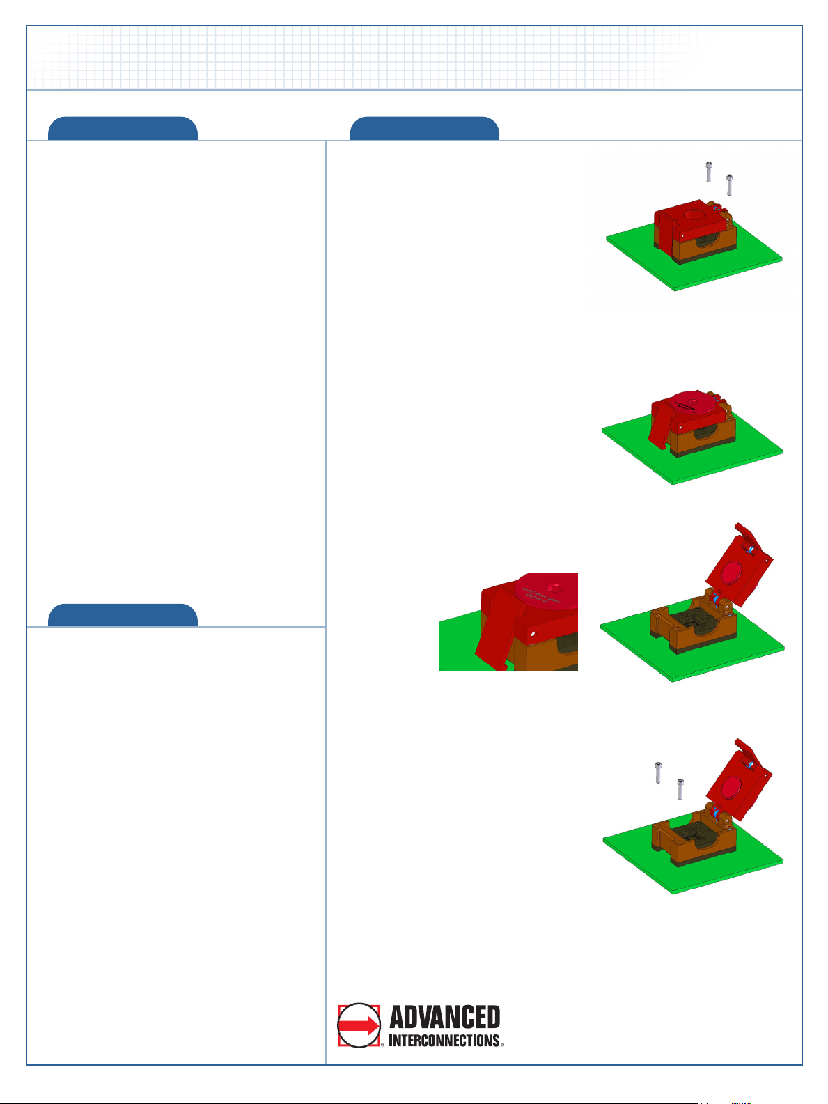
STEP 3
Install supplied #0-80 screws in rear
of socket as shown in Fig. 3 and
tighten using the supplied hex
wrench (recommended torque value
is 1.20 lb-in).
STEP 4
Open lid by pressing upper portion
of latch mechanism back toward
socket (see Fig. 4 and 4a).
Lid will open approximately 115º,
allowing access to the front two
screw locations and allowing for
device insertion (see Fig. 4b).
STEP 5
Install supplied #0-80 screws, as
shown in Fig. 5, and tighten using
the supplied hex wrench
recommended torque value is
1.20 lb-in).


