Advanced Axis AX-ASW-16 User manual

www.advancedco.com
Switch LED Modules
24V
-+
485
B A
PSU
MONITOR
+ --+
-+ + -
-+ + -
-+
1234567
ON
AX-ASW-16 AX-I/O-48
AX-LED16RY AX-LED32R /AX-LED32Y

www.advancedco.com2
Table of Contents Page
1INTRODUCTION / OVERVIEW............................................................................................................................3
1.1PRODUCT DESCRIPTION..................................................................................................................................3
2MODULE INSTALLATION...................................................................................................................................4
2.1AXISAX ENCLOSURE MOUNTING ......................................................................................................................4
2.2AX-LZA CABINET MOUNTING .........................................................................................................................5
2.3AX-I/O-48 OTHER CABINET MOUNTING ..........................................................................................................6
2.3.1AX-GCAB Mounting .................................................................................................................................6
3MODULE DIP SWITCH CONFIGURATION.........................................................................................................7
3.1ADDRESSING (4 DIP SWITCHES).....................................................................................................................7
3.2485 COMMS EOL &DISABLE PSU MONITOR (2 DIP SWITCHES)......................................................................7
3.2.1485 Comms (P-BUS) EOL .......................................................................................................................7
3.2.2Disable PSU (Power Supply Unit) Monitor...............................................................................................8
4MODULE WIRING................................................................................................................................................8
4.124 VDC POWER WIRING.................................................................................................................................8
4.2485 (AX SERIES P-BUS) WIRING ...................................................................................................................9
4.324 VDC &485 (AX SERIES P-BUS) DAISY CHAIN WIRING..............................................................................9
4.4PSU (POWER SUPPLY UNIT)MONITOR WIRING .............................................................................................10
4.5AX-I/O-48 INPUT /OUTPUT WIRING ..............................................................................................................10
5SWITCH LED MODULE PROGRAMMING........................................................................................................11
5.1LED PROGRAMMING ....................................................................................................................................14
5.2SWITCH PROGRAMMING................................................................................................................................17
5.3BUZZER OPERATION PROGRAMMING.............................................................................................................18
6MODULE SLIDE-IN LABELS.............................................................................................................................19
7SPECIFICATIONS..............................................................................................................................................20

www.advancedco.com
www.advancedco.com 3
1 Introduction / Overview
1.1 Product Description
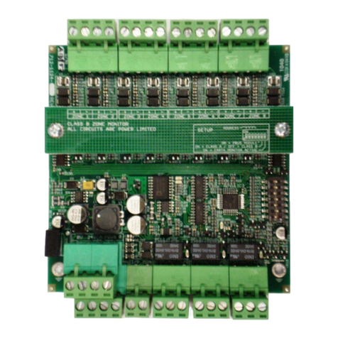
This manual covers the installation and operation of the AxisAX Switch LED Modules (AX-ASW-16, AX-I/O-48, AX-
LED16RY, AX-LED32R and AX-LED32Y).
AX-ASW-16 Switch LED Module, incorporating 16 switches and 48 LEDs
AX-I/O-48 Switch LED Driver Module, incorporating 16 switch inputs and 48 LED Drive Outputs
AX-LED16RY LED Module, incorporating 16 red and 16 yellow LEDs
AX-LED32R LED Module, incorporating 32 red LEDs
AX-LED32Y LED Module, incorporating 32 yellow LEDs
The Switch LED Modules are field configurable switch input and LED status indicator modules for use with
Advanced AxisAX fire alarm control panels. Each fire alarm control panel can accommodate a maximum of sixteen
(16) Switch LED Modules in any combination.
In addition to the switch and LED functionality, each module has an on-board programmable buzzer (piezo) for local
alerting of system status, events, etc.
The AxisAX Switch LED Modules are extremely flexible and easy to configure/program utilizing the Advanced PC-
NeT field configuration tool, which works in a Windows® environment. Switches can be programmed to bypass
(disable/enable) points, zones, and/or groups. They can also be programmed to turn On/Off relay points, NAC
circuits, city connections, or they can be configured to provide complete HOA (Hand-Off-Auto) control functionality.
When interfacing to AxisAX audio and command centers, controls can be configured for all call, selective zone/area
paging, individual message selection, fire fighter telephone selection, etc. LEDs can be programmed for a number
of different status indications by points, zones and/or groups within the system, including alarm, supervisory,
trouble, switch active, relay active, etc. In addition, the LEDs can be programmed for primary and secondary status
events, along with flash rates based on last known status/event (i.e.: off, on steady, 1/2 or 1 second flash). Easy
slide-in label pockets are provided on all modules, except the AX-I/O-48, allowing switches and LEDs to have
customized labeling based on installation usage.

www.advancedco.com4
2 Module Installation
2.1 AxisAX Enclosure Mounting
The Switch LED Modules can be mounted into any available inner (AX-CTL-1 outer) door aperture of an AxisAX
enclosure (see figure 1).
AX-CTL-1
AX-CTL-1V, 2V or 4V AX-CTL-1L, 2 or 4
AX Command Center (3x5)
AX Command Center (3x3)
Figure 1 – Switch LED Module Enclosure Mounting
Inner (AX-CTL-1
outer) door
opening/slot

www.advancedco.com
www.advancedco.com 5
Note: The AX-ASW-16 switch LED module cannot be installed on the outer door of the AX-CTL-1 panel, as
there is no method of disabling (enable/disable key switch control) operation of the 16 switches associated
with the module.
To install a Switch LED Module in an AxisAX panel aperture (opening/slot), simply remove the nuts and washers
holding the blank aperture in place and replace it with the Switch LED Module (see figure 2).
2.2 AX-LZA Cabinet Mounting
In addition to being mounted in an AxisAX enclosure, Switch LED Modules can also be mounted in an Advanced
local zone annunciator cabinet. Advanced has three sizes of local zone annunciator cabinets, an AX-LZA-CAB1,
AX-LZA-CAB2 and an AX-LZA-CAB4. The AX-LZA-CAB1 has a single aperture (opening/slot), while the AX-LZA-
CAB2 has two apertures (openings/slots) and the AX-LZA-CAB4 has four apertures [openings/slots] (see figure 3).
Note: AX-LZA-CAB’s are available in gray or red colors.
AX-LZA-CAB1 AX-LZA-CAB2
Figure 3 – Remote Switch LED Module Cabinet
Figure 2 – Switch LED Module Enclosure Aperture Mounting
AX-LZA-CAB4

www.advancedco.com6
To install a Switch LED Module in a local zone annunciator cabinet, remove the inner plate of the AX-LZA-CAB by
removing the four (4) screws holding the inner plate to the cabinet and removing the inner plate ground wire from
the cabinet pluggable ground stud. Place the Switch LED Module between the four (4) module mounting studs and
secure with the provided washers and nuts (see figure 4). Replace the inner plate and ground wire to the AX-LZA-
CAB.
Note: For detailed AX-LZA-CAB mounting instructions refer to installations instructions provided with the
AX-LZA-CAB.
2.3 AX-I/O-48 Other Cabinet Mounting
In addition to being mounted in cabinets previously mentioned, the AX-I/O-48, Switch LED Driver Module, can also
be installed in an Advanced AX-GCAB (Listed general cabinet) or an ANSI/UL Listed 3rd party annunciator
enclosure.
2.3.1 AX-GCAB Mounting
Mount the Advanced AX-GCAB, general purpose UL Listed enclosure, in a clean, dry environment. Remove the
AX-I/O-48 module from its shipping package and securely install it within the AX-GCAB enclosure with the stand-
offs and screws provided with the AX-I/O-48 module (see figure 5).
AX-LZA-CAB1
Inner Door
AX-LZA-CAB2
Inner Door
Figure 4 – Switch LED Module Remote Cabinet Mounting
Figure 5 – AX-I/O-48 General Purpose Cabinet Mounting
AX-LZA-CAB4
Inner Door

www.advancedco.com
www.advancedco.com 7
3 Module DIP Switch Configuration
3.1 Addressing (4 DIP Switches)
Each Switch LED Module must be connected to the AxisAX panels P-BUS (RS-485 serial communication bus),
located on the AX-CTL base card. As the Switch LED Modules reside on the AX-CTL P-BUS, each module must
be configured with a unique address (see figure 6). The address setting corresponds to P-BUS programming criteria
utilized within the Advanced PC-NeT, field configuration program.
As previously stated, up to 16 (sixteen) Switch LED Modules (any combination) can be connected to a single AxisAX
AX-CTL base card, P-BUS.
Note: Only 16 (16) Switch LED Modules can be connected to a single AxisAX AX-CTL base card.
3.2 485 Comms EOL & Disable PSU Monitor (2 DIP Switches)
In addition to the DIP switches provided for module addressing, each Switch LED Module has two additional DIP
switches, DIP switch 6 and 7. DIP Switch 6 is for activating an onboard resistor to allow for AX-CTL base card P-
BUS (RS485) end-of-line filtering. Dip switch 7 is for allowing the monitoring of a remote power supply.
3.2.1 485 Comms (P-BUS) EOL
The P-BUS (RS485 communications bus) of the AX-CTL base card requires a 150Ωend-of-line filtering resistor to
be placed on the last (furthest) P-BUS module connected to this Style 4 (Class B) communications bus. If a Switch
LED Module is the last module on the P-BUS, set DIP switch 6 on the module to “ON”, thereby activating the
internal 150Ωend-of-line filtering resistor (see figure 6). If the Switch LED Module is not the last module on the P-
BUS, leave DIP switch 6 in its “OFF” position.
Note: DIP switch 6 on the Switch LED Module should only be in set to its “ON” position if the Switch LED
Module is the furthest (last) P-BUS module from the AxisAX AX-CTL base card.
Figure 6 – Switch LED Module DIP Switch

www.advancedco.com8
3.2.2 Disable PSU (Power Supply Unit) Monitor
Each Switch LED Module requires 24 VDC filtered and regulated power at 60mA maximum current draw. The 24
VDC power can be obtained from either the AX-CTL base card (AUX-2, non resettable power output), if available,
or from an ANSI/UL Listed fire alarm power supply. If power is from an ANSI/UL Listed fire alarm power supply, the
Switch LED Module has the capability of monitoring a normally closed trouble contact of the Listed power supply,
thereby providing power supply status reporting at the AxisAX panel.
If monitoring an ANSI/UL Listed fire alarm power supply, leave DIP switch 7 set to the “OFF” position and wire the
two PSU Monitor terminals to the normally closed trouble relay contact of the Listed power supply (see figure 6 and
7). If not monitoring an ANSI/UL Listed fire alarm power supply, set DIP switch 7 to the “ON”, “Disable PSU
Monitor” position (see figure 6).
Note: Normally when the Switch LED Module is mounted to an aperture (opening/slot) location in an AxisAX
panel, power for the module is obtained from AUX 2 of the AX-CTL base card. If the power is originating
from AUX 2 of the base card, set DIP switch 7 to the “ON”, “Disable PSU Monitor” position.
4 Module Wiring
This equipment is constructed with static sensitive components. Observe anti-static
precautions at all times when handling printed circuit boards. Wear an anti-static ground
(earth) strap connected to the system enclosure ground.
The Switch LED Module must be grounded; this is normally achieved via the secured mounting of
the module to the installation cabinet aperture (opening/slot). Should another method of mounting
be utilized a dedicated ground must be provided.
4.1 24 VDC Power Wiring
As previously indicated, each Switch LED Module requires 24 VDC filtered and regulated power. Wire 24 VDC
(60mA maximum) to terminals + and – of the switch LED module (see figure 8).
Figure 7 – Switch LED Module PSU Monitor Wiring
ATTENTION
OBSERVE PRECAUTIONS
FOR HANDLING
ELECTROSTATIC
SENSITIVE DEVICES
Must be
Grounded

www.advancedco.com
www.advancedco.com 9
Note: When utilizing multiple Switch LED Module’s, within the same enclosure, 24 VDC power and the P-
BUS (485) communications can be daisy chained from the first Switch LED Module to the next module, then
from that module to the following module, etc.
4.2 485 (AX Series P-BUS) Wiring
Connect the P-BUS (RS485 serial communications) terminals A and B of the AxisAX AX-CTL base card to the 485 A
and B input terminals of the Switch LED Module (see figure 8). If this is the last module connected to the AX-CTL
P-BUS (RS485 serial communications), set DIP switch 6 (485 Comms EOL) one the Switch LED Module to the
“ON” position (see figure 6).
Note: When utilizing multiple Switch LED Module’s, within the same enclosure, 24 VDC power and the P-
BUS (485) communications can be daisy chained from the first Switch LED Module to the next module, then
from that module to the following module, etc.
4.3 24 VDC & 485 (AX Series P-BUS) Daisy Chain Wiring
When utilizing multiple Switch LED Modules within the same enclosure, the 24 VDC power and P-BUS (485)
communications can be daisy chained from one module to the next module.
Wire 24 VDC and the P-BUS (RS485 communications) to the screw terminal inputs on the first Switch LED Module
(see figure 8). Plug the supplied 10-Way (IDC) ribbon cable into the PL2 (10 pin) serial connection on the Switch
LED Module, connect the other end of the 10-Way (IDC) ribbon cable into the PL3 (10 pin) serial connection on the
next Switch LED Module (see figure 9). This method of distributing both the power and communications can be
continued to other Switch LED Modules, however power requirements must be monitored to confirm there is
enough power to supply all of the connected modules.
Figure 8 – Switch LED Module Wiring

www.advancedco.com10
4.4 PSU (Power Supply Unit) Monitor Wiring
Each Switch LED Module has the capability of monitoring a normally closed trouble contact of a remote ANSI/UL
Listed fire alarm power supply, thereby providing power supply status reporting from a remote location back to the
AxisAX panel.
If monitoring a remote power supply, leave DIP switch 7 set to the “OFF” position and wire the two PSU Monitor
terminals to the normally closed trouble relay contact of the Listed power supply (see figure 10).
4.5 AX-I/O-48 Input / Output Wiring
In addition to the power supply and P-BUS wiring, each AX-I/O-48, Switch LED Driver Module, has 16 hardwired
switch inputs and 48 hardwired LED drive outputs. Wire inputs 01 thru 16, + and –, to ANSI/UL Listed switch. Wire
LED drive outputs 01 to 48, + and –, to the associated ANSI/UL Listed LED. The LED drive output, + and -, is
current limited (see figure 11).
Figure 9 – Switch LED Module Daisy Chain Wiring
24V
-+
485
B A
PSU
MONITOR
-+
1234567
ON
24V
-+
485
B A
PSU
MONITOR
-+
1234567
ON
Figure 10
–
Switch LED Power Supply Monitor Wiring

www.advancedco.com
www.advancedco.com 11
5 Switch LED Module Programming
Each Switch LED Module must be programmed for panel recognition and functionality utilizing the latest PC-NeT,
Field Configuration Programming.
The following is a quick reference guide on how to set up inputs (switches) and outputs (LEDs). It is not intended
as, nor does it come close to being, an exhaustive list of the available options associated with the Switch LED
Module programming capabilities.
Before the Switch LED Module can be programmed, it must be added to the PC-NeT like any other device/module.
Select the Switch LED Module type (Switch LED Card, IO Card, Red/Yellow LED Card, Red LED Card or Yellow
LED Card) under the Peripheral Bus, Device Selector, Peripheral Bus Interfaces of the Ax4-CTL-4 and double click
the associated peripheral bus address (26 thru 41 [module address 0 thru 15 respectively]). Correlation of the
switch LED module address is DIP switch address 0 = peripheral bus address 26, address 1 = peripheral bus
address 27, etc, etc, to address 15 equaling peripheral bus address 41.
Figure 12 shows an example of peripheral bus address 26 being allocated to a Switch LED Card (DIP switch
address 0), peripheral bus address 27 being allocated to an IO Card (DIP switch address 1), peripheral bus address
28 being allocated to a Red/Yellow LED Card (DIP switch address 2), peripheral bus address 29 being allocated to
a Red LED Card (DIP switch address 3) and peripheral bus address 30 being allocated to a Yellow LED Card (DIP
switch address 4).
24V
-+
485
B A
PSU
MONITOR
-+
Output 21
Output 23
Output 22
Output 24
Output 25
Output 26
Output 27
Output 28
Output 29
Output 30
1234567
ON
Figure 11 – AX-I/O-48 Switch Input / LED Driver Output Wiring

www.advancedco.com12
Note: Any Switch LED Module can be allocated to peripheral bus addresses of 26 to 41 (DIP switch
addressing 0 thru 15). However, only sixteen (16) Switch LED Module’s (of any type) can be added to a
single AxisAX AX-CTL base card P-BUS (RS485 serial communications).
To program the specific peripheral bus Switch LED Module, click on the peripheral bus module and then click on the
(magnifying glass) button. This will bring you to the specific module programming area (see figure 13, 14,
15).
Figure 5
Figure 12 – Switch LED Module Peripheral Bus Programming

www.advancedco.com
www.advancedco.com 13
Figure 13 – AX-ASW-16 Programming Area Screen
Figure 14 – AX-I/O-48 Programming Area Screen

www.advancedco.com14
In these various programming areas you are now able to click on the various points (inputs [switches] and outputs
[LEDs]) and program unique I/O functionalities.
5.1 LED Programming
Click on an LED of the Switch LED Module, the LED will illuminate and an LED Operation area will open up on the
bottom left-hand side of the screen.
Within the LED Operation area, you should assign a Function Description for the LED. After assigning a Function
Description, click on the “Unused” description within the Primary Activation Operating Method and a drop down
menu will appear allowing you to select the Operating Method of the LED; General Event, Single Zone, Output
Group or Disable Group control.
Figure 15 – AX-LED16RY, AX-LED32R, AX-LED32Y Programming Area Screen

www.advancedco.com
www.advancedco.com 15
If you were programming a zone alarm LED you would select “Single Zone”, then you would select the zone number
that will activate this LED (default zone 1). If we wanted to distinguish this LED if this were the first zone to alarm in
the system, you could check the box next to “Flash if Fire Started Here”. As the default activation Qualifier is for an
alarm condition no further programming is required, when an alarm occurs in zone 1, the associated red LED will
illuminate.
If you wanted to also program a zone trouble LED, you would click on the yellow LED, the yellow LED would
illuminate and the LED Operation area will open up on the bottom left-hand side of the screen:
Within the LED Operation area, you would assign a Function Description for the LED and click on the “Unused”
description, within the Primary Activation Operating Method and a drop down menu will appear. You would then
select Single Zone:
After selecting “Single Zone”, you would select the zone number that will activate this LED (default zone 1).
Note: All LEDs default to an Alarm qualifier, so if you want to program the LED to activate from a trouble
you need to remove (uncheck) the Alarm qualifier and add the trouble qualifier (check).

www.advancedco.com16
In addition, if we want the yellow LED to also illuminate when an input or output is disabled within this zone, you
would also need to select (check) “Any Input Disabled” and “Any Output Disabled”.
For additional flexibility each LED can also be programmed for a secondary activation, such that if you wanted the
yellow LED to be steady on for trouble and flash for a disablement, you could program this functionality within the
Secondary Activation Operating Method. If you want to distinguish a disablement from a trouble, you could program
the LED for a Secondary Activation, where the LED would flash for disablement, see below. Primary Activation of
the LED is Steady ON when there is a trouble; secondary activation of the LED is Flash half second if there is a
disablement within the zone. As the trouble qualifier is the primary activation if there were a trouble and a
disablement within the zone at the same time the LED would be steady ON.

www.advancedco.com
www.advancedco.com 17
5.2 Switch Programming
Clicking on a switch or input of a Switch LED Module will highlight the switch or input on the switch LED module. In
addition, it will open up a Point Details area on the bottom left-hand side of the screen:
Within the Point Details area for the specific button (switch) or input you should assign a location text, for example;
“Zone 1 Bypass”. After assigning a location text, click on the “No Action” description of the “Input Action” within the
Point Details area. A drop down menu will appear, scroll to the specific Input Action you would like the switch/input

www.advancedco.com18
to perform. There are a number of Input Actions a switch or input can be assigned such as, create an alarm,
activate a control signal, disable a group of devices, disable a zone, acknowledge an event, reset the panel,
perform a drill, be an all call switch for audio, be a selective page switch, a lamp test a switch, etc.
Note: Based on the switch input action, programming of the switch type will be required, for example,
toggle (toggle on/off) or push button (one press activates requirements i.e. acknowledge, reset).
If you were programming a zone disable (bypass) switch, you would select the “Disable Zone” action. Once the
Disable Zone action has been selected you would input the zone number you’d like to disable within the
Disablement Zone number area (default is zone 1).
5.3 Buzzer Operation Programming
Each Switch LED Module has a programmable buzzer (piezo). The default programming of the buzzer is “Unused”.
Like the LED programming of a switch LED module, the buzzer can be programmed for primary and secondary
activation.
Clicking on the buzzer of the module being programmed will open up a Buzzer Operation area on the bottom left-
hand side of the.
Within the Buzzer Operation area, you should assign a Function Description for the buzzer. After assigning a
Function Description, click on the “Unused” description within the Primary Activation Operating Method and a drop
down menu will appear allowing you to select the Operating Method of the buzzer; General Event, Single Zone,
Output Group or Disable Group control.

www.advancedco.com
www.advancedco.com 19
6 Module Slide-in Labels
Each Switch LED Module, with the exception of the AX-I/O-48, incorporates a slide-in label pocket for installing
customized installation labels. To install a customized label, whether the Switch LED Module has been installed in
an AxisAX enclosure or not, simply slide the previously installed label out of the slide-in pocket, located at the top of
the module, and slide the installation specific customized label into the pocket (see figure 16).
Note: Microsoft Word formatted label templates are available and provided to customers during factory
training. If you require the Word formatted labels contact Advanced. In addition, the Word formatted label
templates are available via the secured area of our web site.
Figure 16 – Module Slide-in Label Pocket

www.advancedco.com20
7 Specifications
Switch LED Module Specifications
Operating Voltage 18-28 VDC (wired from FACP 24 VDC or a ANSI/UL Listed power supply)
Operating Current 60mA maximum
Current typical – all outputs OFF: 11mA
Current typical – all outputs ON: 50mA
Temperature 32–120
0
F (0-48
0
C)
Humidity 10-95% (non condensing)
Mechanical Module plate for aperture mounting
Dimension (including plate) 6.61”H x 5.66”W x 1.2”D
Weight 11 oz
Inputs
Switch (AX-ASW-16)
Switch Input (AX-I/O-48)
Power Supply Monitor
16 programmable toggle or push button switches
16 programmable inputs
Normally closed (N/C) contact monitoring
Outputs
LED (AX-ASW-16)
LED (AX-LED16RY)
LED (AX-LED32R)
LED (AX-LED32Y)
LED Output (AX-I/O-48)
Buzzer
48 programmable LEDs (16 Green, 16 Red, 16 Yellow)
32 programmable LEDs (16 Red, 16 Yellow)
32 programmable red LEDs
32 programmable yellow LEDs
48 programmable LED drive outputs (current limited)
Programmable on-board buzzer (piezo)
Terminal Wire Size 12 - 24 AWG
Daisy Chain Connection 10-way IDC ribbon cable
As our policy is one of constant product improvement the right is therefore reserved to modify product specifications without prior notice
Doc Number: 682-021 AFS
Revision: 2.1
First Issued: 2013-mm-dd
100 South Street, Hopkinton, Massachusetts 01748
Tel: (508) 435-9995 Fax: (508) 435-9990
Email: usa@advancedco.com Web: www.advancedco.com
This manual suits for next models
4
Table of contents
Other Advanced Control Unit manuals
Popular Control Unit manuals by other brands

Huawei
Huawei MU509-65 Hardware guide
National Instruments
National Instruments NI 9882 Getting started guide
Pfeiffer Vacuum
Pfeiffer Vacuum EVB 063 PA instruction sheet
Spirax Sarco
Spirax Sarco HP70 Series Installation and maintenance instructions

Trane
Trane BAYLOAM105AA Installer's guide
Vicon
Vicon V1411-EXP instruction manual
