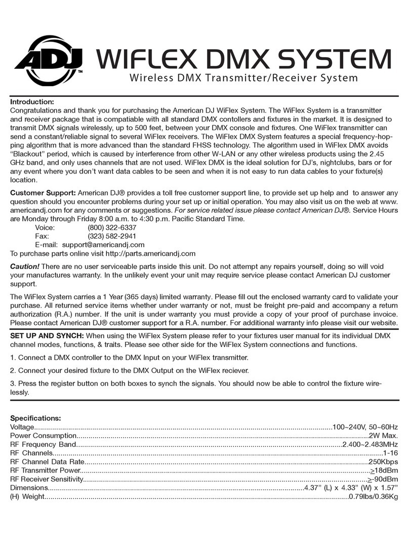
Advanced Axis D9068 User manual

www.advancedco.com
D9068P DACT
Digital Alarm Communicator Transmitter
D9068
Installation & Operation Manual

www.advancedco.com
2
Table of Contents Page
1OVERVIEW...........................................................................................................................................................6
1.1SYSTEM OVERVIEW ........................................................................................................................................6
1.2FEATURES AND SPECIFICATIONS.....................................................................................................................6
1.2.1Power.......................................................................................................................................................6
1.2.2System Supervision .................................................................................................................................6
1.2.3Trouble Contact........................................................................................................................................6
1.2.4User Interface...........................................................................................................................................7
1.2.5Communication........................................................................................................................................7
1.2.6History Buffer ...........................................................................................................................................7
1.2.7General Specifications.............................................................................................................................8
1.2.8Parts List..................................................................................................................................................8
1.1.1AX-SEB Serial Expansion Board Layout ...............................................................................................10
2INSTALLATION..................................................................................................................................................11
2.1D9068P MOUNTING WITHIN THE AX-CTL-1 ENCLOSURE ................................................................................11
2.2D9068P MOUNTING WITHIN THE /E AND /V ENCLOSURE (AX-CTL-1L, -2 AND -4)............................................13
2.3AX-SEB MOUNTING TO AX-CTL-1, -1L, -2 AND -4 BASE CARDS...................................................................15
2.4INSTALLING TELCO CABLE ASSEMBLIES........................................................................................................15
2.4.1Telephone Connections.........................................................................................................................16
2.5CONNECTING THE DACT-PRG LCD KEYPAD TO THE AX-SEB MODULE........................................................17
3D9068P START UP............................................................................................................................................17
3.1AX SERIES INTELLIGENT FIRE ALARM CONTROL PANEL AND D9068P POWER UP ..........................................18
3.1.1Before Powering up................................................................................................................................18
3.1.2After Power up .......................................................................................................................................18
3.2D9068P QUICK START.................................................................................................................................18
4D9068P OPERATION.........................................................................................................................................19
4.1COMMUNICATOR OPERATION ........................................................................................................................19
4.1.1Phone Line and Phone Number Selection.............................................................................................19
4.1.2Telephone Line Supervision ..................................................................................................................20
4.1.3Wait for Dial Tone ..................................................................................................................................20
4.1.4Call Routing............................................................................................................................................20
4.1.5Call Attempts..........................................................................................................................................21
4.1.6Communication Fault.............................................................................................................................21
4.1.7Programming Fault.................................................................................................................................21
4.1.8Lost Data and Limited Reports ..............................................................................................................21
4.1.9Communications Tests...........................................................................................................................22
4.2KEYPAD OPERATION ....................................................................................................................................23
4.2.1DACT-PRG LCD Keypad.......................................................................................................................23
4.2.2Scrolling Menus......................................................................................................................................24
4.2.3Selecting Menu Items.............................................................................................................................25
4.2.4History....................................................................................................................................................26
4.3RESET..........................................................................................................................................................27
5PROGRAMMING................................................................................................................................................27
5.1USING THE KEYPAD......................................................................................................................................27
5.2PROGRAMMING KEY SEQUENCES..................................................................................................................28
5.3PROGRAMMING MENU TREE..........................................................................................................................30
5.4PROGRAMMING THE D9068P........................................................................................................................33
5.4.1PROG TIME...........................................................................................................................................33
5.4.2PROG TIMERS......................................................................................................................................34
5.4.3PROG INPUTS ......................................................................................................................................35
5.4.4PROG RELAY........................................................................................................................................36

www.advancedco.com 3
www.advancedco.com 3
5.4.5PROG ACC’NTS....................................................................................................................................36
5.4.6PROG FORMATS..................................................................................................................................39
5.4.7PROG DEFLTS......................................................................................................................................40
5.4.8SERIAL CONECTN ...............................................................................................................................40
5.5OPERATING MODES......................................................................................................................................40
5.5.10- PROGRAM ........................................................................................................................................41
5.5.21- STATUS.............................................................................................................................................41
5.5.32- HISTORY...........................................................................................................................................41
5.5.43- TEST..................................................................................................................................................41
5.5.54- RESET...............................................................................................................................................41
6APPENDIX A: TROUBLESHOOTING...............................................................................................................42
6.1ON-BOARD LEDS........................................................................................................................................42
6.2INPUT POINTS...............................................................................................................................................43
6.3TROUBLE RELAY..........................................................................................................................................43
6.4MANUAL TEST REPORT FAILURE...................................................................................................................43
6.5REPORTS IN QUEUE......................................................................................................................................43
6.6ERROR DURING COMM TEST.........................................................................................................................44
7APPENDIX B: D9068P REPORTING ................................................................................................................45
8APPENDIX C: D9068P PROGRAMMING DEFAULTS.....................................................................................49
9APPENDIX D: REPORT ROUTING...................................................................................................................51

www.advancedco.com
4
Notices
FCC Compliance Notice
This equipment was tested and complies with the limits for a Class A digital device, pursuant to Part 15 of the
Federal Communications Commission (FCC) Rules. These limits are designed to provide reasonable protection
against harmful interference in a commercial installation. This equipment generates, uses, and can radiate radio
frequency energy. When this equipment is not installed and used according to the instructions, it might cause
harmful interference to radio communications. There is no guarantee that interference will not occur in a particular
installation. If this equipment causes harmful interference to radio or television reception that can be determined by
turning the equipment off and on, correct the interference by:
• Reorienting or relocating the receiving antenna.
• Increasing the separation between the equipment and the receiver.
• Connecting the equipment to an outlet on a circuit different from that the receiver is connected to.
• Consulting the dealer or an experienced radio or TV technician for help.
FCC Telephone Connection to Users
This control complies with Part 68 of the FCC rules. The ringer equivalence number (REN) for this equipment is
0.0B. When requested, you must provide this information to your local telephone company. The REN helps
determine the quantity of devices that can be connected to your telephone line and still have all of those connected
devices ring when your telephone number is called. In most areas the sum of the RENs of all devices connected to
one line should not exceed five (5.0). To verify the number of devices you can connect to your line, contact your
local telephone company to determine the maximum REN for your local calling area. The FCC registration number
is ESVMUL-46514-AL-E. The ringer equivalence is 0.0B. Do not use this equipment on coin service provided by
the telephone company or connected to party lines. If this equipment harms the telephone network, the telephone
company might temporarily discontinue your service. When possible, the telephone company notifies you in
advance. If advanced notice is not practical, you are notified as soon as possible. You are informed of your right to
file a complaint with the FCC.
The telephone company can make changes in its facilities, equipment, operations, or procedures affecting the
proper functioning of your equipment. If they do, you are notified in advance so you can maintain uninterrupted
telephone service.
If you experience trouble with this equipment, contact the Installing Distributor or Advanced for information on
obtaining service or repairs.
The telephone company might ask you to disconnect this equipment from the network until the problem is corrected,
or until you are sure the equipment is not malfunctioning.
Operating this equipment can also be affected if events such as accidents or acts of God interrupt telephone
service.
Industry Canada Notice
The Industry Canada label identifies certified equipment. This certification means the equipment meets certain
telecommunications network protective, operational, and safety requirements. Industry Canada does not guarantee
the equipment operates to the user’s satisfaction.
Before installing this equipment, verify you have permission to connect it to the facilities of the local
telecommunications company. Install the equipment using an acceptable method of connection. Verify the customer
is aware that compliance with the above conditions might not prevent degradation of service in some situations.
An authorized Canadian maintenance facility, designated by the supplier, should make the repairs to the certified
equipment. If you make repairs or modifications to this equipment, and if the equipment malfunctions, the
telecommunications company might ask you to disconnect the equipment.
For your own protection, ensure the electrical ground connections of the power utility, telephone lines, and
internal metallic water pipe s
y
stem, if present, are connected to
g
ether.
Do not attempt to make such connections. Contact the appropriate electric inspection authority or electrician.
The manufacturer, not the user, must make the repairs to this equipment.

www.advancedco.com 5
www.advancedco.com 5
Installation Guidelines for UL Systems
D9068P UL Requirements
• D9068P is UL Listed for Commercial Digital Alarm Communicator applications (Type service: remote station and
central station), UL Standard UL864.
• Install the digital alarm communicator transmitter (DACT) according to NFPA 72 for Commercial Fire installations.
• Use, enable, and supervise both telephone lines.
Failure to install and program the D9068P according to the requirements in this section voids its listing mark.
Test according to NFPA 72 following any modifications, repairs, upgrades, or adjustments to the system.

www.advancedco.com
6
1 Overview
1.1 System Overview
The D9068P Fire Communicator is a complete communicator for use with AX Series Intelligent Fire Alarm Control
Panels. Alarms and communications to the D9068P are accomplished via serial connection. The D9068P includes:
Multiple data protocols (Contact ID, and SIA 300)
100-event history buffer
Dual telephone line interface
Connections for programming LCD Keypad (DACT-PRG)
LEDs for heartbeat, DACT trouble, and telephone line trouble (one per line)
Serial port for connection to the AX Series Intelligent Fire Alarm Control Panel
Real-time clock
1.2 Features and Specifications
1.2.1 Power
Table 1: Power Specifications
Input Voltage 10.2 to 28 VDC
Standby Current 150 mA
Alarm Current 190 mA
Power for the D9068P is wired directly to the AX Series Intelligent Fire Alarm Control Panel via the AX-SEB cable.
Although the D9068P can withstand short power losses up to 5 minutes, power losses (AC & DC) greater than 5
minutes, could possibly cause the following:
History buffer might clear and all stored events are lost.
Output (report) buffer might clear and all pending reports are lost.
Alarms initiated before the power loss might reset. If the alarm conditions persist when power is restored,
new alarms will be generated.
DACT time might reset to its default setting.
1.2.2 System Supervision
Watchdog: The D9068P is supervised with a hardware watchdog circuit. Failure of the control program causes a
hardware reset within 2 sec. The AX Series Intelligent Fire Alarm Control Panel will indicate a DACT trouble
condition under this situation.
Self Testing: Occasionally, the dialer (DACT), EEPROM memory, and telephone lines are automatically tested.
The EEPROM checksum is verified every 10 minutes. If the EEPROM checksum fails, a DACT trouble condition is
indicated on the AX Series Intelligent Fire Alarm Control Panel and a Trouble Report is sent to the Central Station.
1.2.3 Trouble Contact
The D9068P has one Form C relay rated 1 Amp @ 30 VDC. The Form C relay is normally held active and
deactivates on any DACT trouble condition.
Note: The trouble contact is not utilized when utilizing the D9068P in conjunction with an AX Series Intelligent Fire
Alarm Control Panel. All DACT trouble conditions are reported to the FACP via the supervised serial connection.
If a power loss occurs, programmed settings such as point configuration, telephone numbers, and account
number remain intact.

www.advancedco.com 7
www.advancedco.com 7
1.2.4 User Interface
A Programming LCD Keypad (DACT-PRG) connects to a five-pin connector located on the AX-SEB board. The
DACT-PRG is used to program and troubleshoot the D9068P.
Note: The DACT-PRG must be set to address 1 for proper use.
1.2.5 Communication
Formats
The D9068P supports two protocols: Contact ID, and SIA 300.
Report Routing
There are six different report groups that can be routed to one of the following phone settings:
PHONE 1 ONLY: The report is sent to Phone #1 only.
PHONE 2 ONLY: The report is sent to Phone #2 only.
PHONE 1 & 2: The report is sent to Phones #1 and #2.
PHONE 2 BACKUP: The report is sent to Phone #1, and then to Phone #2 if Phone #1 fails.
These reporting groups consist of non-supervisory alarms (NONSUP ALRM), supervisory alarms (SUPVSY ALRM),
alarm restoral’s and resets (ALM RSTR, RST), supervisory restoral’s (SUPVSY RSTR), tests (TESTS), and troubles
and trouble restoral’s (TBL, TBL RSTR).
Reset Report
A Reset Report is issued when the D9068P is reset from any off normal condition.
Telephone Line Selection
The D9068P follows a predetermined sequence to choose between the two telephone lines. It also implements the
new NFPA requirements for alternating telephone lines during test reporting. The D9068P maintains a variable that
selects either Phone Line 1 or Phone Line 2 for Auto Test Reports. After each successful Test Report, the variable
switches to select the other telephone line.
Users can select the telephone line for Manual Test Reports.
Communication Failed Indication: The D9068P indicates a communication failure after ten attempts to
communicate are completed without success. This causes an AX Series Intelligent Fire Alarm Control Panel DACT
trouble.
1.2.6 History Buffer
The D9068P has a history buffer that retains up to 100 events. Each event is tagged with the date and time of
occurrence. This buffer can be viewed when a DACT-PRG is attached to the AX-SEB board. When the buffer is full,
old events are discarded to make room for new events. A watchdog reset is entered in the buffer and does not reset
the buffer.
The history buffer might clear when the system loses AC and DC power for more than 5 min.
Only use the DACT-PRG LCD Keypad to program the D9068P. Temporarily connect this unit to the D9068P for
programming only.

www.advancedco.com
8
1.2.7 General Specifications
Table 2: General Specifications
Storage/Operating
Temperature 32
0
F to 120
0
F
(00C to 490C)
Lightning
Protection Metal oxide varistors (MOVs) and spark gaps provide protection from lightning surges and static
discharges for inputs and telephone interface.
1.2.8 Parts List
Table 3: Parts List
1 D9068P Serial DACT PC board
4 DACT PC board mounting clips and screws (not required for AX Series use)
4 sets cable assemblies
(only DACT-PRG cable assembly required, others not required with AX Series use)
2 sets telco cable assemblies RJ31X
1 ground wire
(not required for AX Series use)
5 end-of-line (EOL) resistors
(not required for AX Series use)
1 AX-SEB Serial Expansion Board
1 AX-SEB ON/OFF jumper
1 AX-SEB PL2 cable
1 AX-SEB PL4 cable
1 AX-SEB round standoff with screw
(required for AX-CTL-1 Mounting)

www.advancedco.com 9
www.advancedco.com 9
2
1
98
3
4
5
6
7
1 – Mounting holes (4) 6 – System (DACT) trouble LED
2 – Phone line 1 7 – Heartbeat LED
3 – Phone line 1 LED 8 – To PL2 cable of AX-SEB
4 – Phone line 2 9 – To PL4 cable of AX-SEB
5 – Phone line 2 LED
Figure 1 – D9068P PC Board Layout

www.advancedco.com
10
1.1.1 AX-SEB Serial Expansion Board Layout
The AX Series Intelligent Fire Alarm Control Panel communicates to the D9068P DACT serially via an AX-SEB
serial expansion board. The AX-SEB Serial Expansion Board plugs into a ten-pin serial expansion port socket
located on the bottom left corner of the AX-CTL Base Card. See figure 2. Refer to Section 2.3 regarding AX-SEB
installation
Note: When utilizing the AX-SEB the jumper must be set in the DACT “ON” position. When programming the AX
Series Intelligent Fire Alarm Control Panel via the PC-NeT software tool the jumper must be placed in the DACT
“OFF” position, and upon completion of programming returned to the DACT “ON” position.
PL2 cable to (8) of D9068P
PL4 cable to (9) of D9068P
DACT-PRG
Ke
yp
ad
p
lu
g
AX Series
Programming
Jumper
Figure 2 – AX-SEB Serial Expansion Board Layout

www.advancedco.com 11
www.advancedco.com 11
2 Installation
The D9068P DACT mounts within any AX Series Intelligent Fire Alarm Control Panel. There are two (2) methods of
mounting the D9068P within an AX Series Intelligent Fire Alarm Control. The first method is for mounting the
D9068P within an AX-CTL-1 enclosure. The second method is for mounting the D9068P within an /E or /V
enclosure (AX-CTL-1L, -2 or -4).
2.1 D9068P mounting within the AX-CTL-1 enclosure
When mounting the D9068P in an AX Series AX-CTL-1, the D9068P is mounted on top of (above) the AX Series
Base Card (if also utilizing an AX-Net4 or 7 network card, the network card would be mounted to the left sidewall of
the enclosure backbox). See figure 3
AC MAINS
BATTERY BATTERY
USB RS23 PBUS AUX DC
OUT
BATTERY
O/C OUT
To Display Card
Network
Card
D9068P
DACT
Figure 3 – D9068P Mounted in AX-CTL-1 Enclosure

www.advancedco.com
12
Remove the two (2) upper middle Regular head screws holding the AX-CTL Base Card to the enclosure back box,
and replace with two (2) metal hexagon spacers (H), provided with the D9068P mounting plate. Install the
remaining two (2) supplied metal hexagon spacers in the two locations directly below the two (2) installed spacers
(H). Do not over tighten metal hexagon spacers as breakage of the spacer can occur. See figure 4
Utilizing four (4) of the Regular head screws provided, install the D9068P mounting plate to the four (4) installed
metal hexagon spacers (R), and tighten securely.
Utilizing the four (4) remaining Regular head screws provided, install the D9068P to the D9068P mounting plate (S),
and tighten securely.
Refer to Section 2.3 regarding AX-SEB mounting and connections.
NC NO COM
SUPERVISORY
NC NO COM
TROUBLE
NC NO COM
FIRE
USB RS232 PBUS AUX DC
OUT BATTERYO/C OUT
OUT OUT IN IN
+ - + -
LOOP-1
LINE 1
HEARTBEAT
LINE 2
SYS TROUBLE
+ + - - A B 1 2 3 4 5 NC C NO
D9068P
D9068P Mounting Plate
HH
HH
R R
R R
S S
S S
Figure 4 – AX-CTL-1, D9068P Mounting Plate and D9068P DACT Installation

www.advancedco.com 13
www.advancedco.com 13
2.2 D9068P mounting within the /E and /V enclosure (AX-CTL-1L, -2 and -4)
When mounting the D9068P in a /E or /V enclosure the D9068P is mounted on the left sidewall of the enclosure
backbox. See figure 5
Located on the upper left sidewall of the /E and /V enclosure backbox are three (3) PC board push snap-on
standoffs (P) and one (1) screw standoff (S). Push the D9068P DACT module onto the three (3) push snap-on
standoffs. Utilizing the supplied Regular head screw, screw the D9068P DACT to the screw standoff (S), and
tighten securely. See figure 6
AC MAINS
USB RS232 PBUS AUX DC
OUT DC IN BATTERY
O/C OUT
To Display Card
To Network Card
AX-RL8
BATTERY BATTERY
AX-PSU
D9068P
DACT
Dedicated
A
C Circui
t
Figure 5 – D9068P Mounted in /E or /V Enclosure

www.advancedco.com
14
With D9068P installation in /E and /V enclosures install the PL2 and PL4 cables of the AX-SEB prior to mounting
the D9068P DACT. Refer to Section 2.3 regarding AX-SEB mounting and connections.
LINE 1
HEARTBEAT
LINE 2
SYS TROUBLE
+ + - - A B 1 2 3 4 5 NC C NO
D9068P
P
P
S
P
Figure 6 – D9068P Installation in /E or /V Enclosure
PL4
PL2

www.advancedco.com 15
www.advancedco.com 15
2.3 AX-SEB mounting to AX-CTL-1, -1L, -2 and -4 Base Cards
Install the round standoff provided with the AX-SEB into the screwed standoff directly below the AX-CTL Base Card
ten-pin serial expansion port socket. The ten-pin serial expansion port socket is located on the bottom left side of
the Base Card PC board.
Plug one end of the PL2 cable into the back of the AX-SEB board (PL2 Slot) and connect the other end of the PL2
cable to the DACT DACT-PRG LCD keypad Molex connector on the D9068P.
Plug one end of the PL4 cable into the back of the AX-SEB board (PL4) and connect the other end of the PL4 cable
into the serial communications and power Molex connector on the D9068P DACT. See figure 8
On the back of the AX-SEB is a ten-pin male serial connector, plug the ten-pin male serial connector into the ten-pin
female connector located on the AX-CTL Base Card. Utilizing the supplied Regular head screw, screw the AX-SEB
module to the installed round standoff, and tighten securely. See figure 7
2.4 Installing Telco Cable Assemblies
Use the supplied Telco cable assemblies to connect to an RJ31X jack. Ensure the RJ31X jacks are mounted in a
secure location to prevent unwanted disconnections or tampering. See figure 8
R
Figure 7 – AX-SEB Mounting to AX-CTL-1, -1L, -2 and -4 Base Cards
ONOFF
PL2
PL4
LINE 1
HEARTBEAT
LINE 2
SYS TROUBLE
+ + - - A B 1 2 3 4 5 NC C NO
PL2PL4
Figure 8 – AX-SEB PL2 and PL4 Cable Connections

www.advancedco.com
16
2.4.1 Telephone Connections
Telephone Cord Installation
Connect the primary phone line to the D9068P Modular Jack Line 1 using a telephone cord. Connect the
secondary phone line to the D9068P Modular Jack Line 2 using another telephone cord.
Location
To prevent jamming of alarm and other reports, wire and locate the RJ31X jack so normal phone use is temporarily
interrupted while the D9068P transmits data. See figure 9
After installation, verify the D9068P seizes the line, acquires dial tone, and reports correctly to the central station
receiver.
Notification
Do not connect registered equipment to party lines or coin-operated telephones. If the local telephone company
requests notification before you connect the D9068P to the telephone network, tell them:
• Which line you are connecting to the DACT.
• The make, model, and serial number of the device.
• The FCC registration number (ESVMUL-46514-AL-E) and ringer equivalence (0.0B).
If the telephone company changes its communications facilities, equipment, operations, or procedures that can
affect the performance of the D9068P, the telephone company is obligated to notify the user in writing.
The D9068P meets the UL1950 requirements.
For all applications, connect separate primary and secondary phone lines to the D9068P
Use the supplied Telco cable assemblies to connect to an RJ31X jack. Ensure the RJ31X jacks are
mounted in a secure location to prevent unwanted disconnections or tamperin
g
.
Figure 9 – RJ31X Wiring

www.advancedco.com 17
www.advancedco.com 17
2.5 Connecting the DACT-PRG LCD Keypad to the AX-SEB Module
Use the DACT-PRG LCD Keypad to program the D9068P DACT
Carefully pry the back cover of the DACT-PRG LCD Keypad off and wire the provided five (5) wire harness (wire
colors; red, two blacks, green, and yellow), with a Molex connector on one end, to the DACT-PRG LCD keypad.
See figure 10
With the back cover still removed confirm that the DACT-PRG LCD Keypad address is set to 1. If not, set the
address by placing one of the provided black jumpers across pins one and two. This will set the address to 1. See
figure 10
Once wired and addressed correctly, the DACT-PRG LCD keypad is capable of being used to program the D9068P
DACT. To program the D9068P DACT simply plug the keypad Molex connector into the AX-SEB connector labelled
Keypad/PL3, located on the lower right corner of the AX-SEB PC board.
3 D9068P Start Up
This section describes the proper sequence of events pertaining to the D9068P DACT when the AX Series
Intelligent Fire Alarm Control Panel is first powered up.
R B G Y
DACT-PRG
LCD Keypad
To PL3
Keypad Connector
on AX-SEB
Figure 10 – DACT-PRG LCD Keypad Wiring and Addressing
1 2 4 8
DACT-PRG
Addressing
While utilizing the DACT-PRG LCD Keypad if no keypad activity occurs for 3 minutes, the DACT-PRG
LCD Keypad’s access will be disabled. When disabled the keypad’s buzzer will sound and a SYSTEM
FAULT message will appear on the DACT-PRG LCD display. To re-establish communications with the
D9068P DACT, simply disconnect the DACT-PRG Molex connector from the AX-SEB and reconnect it.
While the DACT-PRG LCD Keypad is connected and being utilized to program the D9068P, the D9068P
does not monitor the connection to the AX Series serial port.

www.advancedco.com
18
3.1 AX Series Intelligent Fire Alarm Control Panel and D9068P Power up
In addition to the power up requirements of the AX Series Intelligent Fire Alarm Control Panel, the following should
be performed with systems that include a D9068P DACT.
3.1.1 Before Powering up
Before applying power to the AX Series FACP, verify:
• That all connections made to the AX-SEB have been done according to this document.
• That all connections made to the D9068P have been made according to this document.
• That all telephone connections have been made to the D9068P according to this document.
• That both RJ31X male connectors are firmly seated in the RJ31X female connectors located on the D9068P
DACT.
3.1.2 After Power up
After power is applied to the AX Series Intelligent Fire Alarm Control Panel, verify the following D9068P conditions
occur:
• All D9068P LEDs briefly light.
• The D9068P System Trouble LED lights.
• The D9068P Heartbeat LED flashes to indicate the D9068P is functional.
3.2 D9068P Quick Start
Upon power up, the D9068P will be in a trouble condition and will not function properly, nor will the D9068P be
supervised by the AX Series Intelligent Fire Alarm Control Panel until the following steps are performed:
1. Program the D9068P.
2. Assign account numbers to the D9068P.
3. Assign telephone numbers to the D9068P.
4. Program the AX Series Intelligent Fire Alarm Control Panel for serial DACT communications.
To program the D9068P and the AX Series Intelligent Fire Alarm Control Panel for proper operation, refer
to the programming section 5 of this manual.
If the D9068P is correctly programmed and input wiring is properly connected, only the Heartbeat LED
should be flashing. This indicates a normal D9068P operation.
To verify correct communications of the D9068P, perform a manual Communications Test. Refer to
section 5.5.4 1: TEST COMM on page 40 for manual communications testing instructions.
Test according to NFPA 72 following modifications, repairs, upgrades, or adjustments to the AX Series
Intelligent Fire Alarm Control Panel and/or D9068P DACT.
Refer to Appendix B beginning on page 44 for information on error messages or messages indicating
abnormal operating conditions.

www.advancedco.com 19
www.advancedco.com 19
4 D9068P Operation
4.1 Communicator Operation
The D9068P has an integrated communicator that sends reports to a monitoring station. The communicator
operates automatically.
When events occur, the communicator sends corresponding reports to the monitoring station by priority according
to NFPA requirements. Fire alarms are sent first, followed by supervisory alarms and trouble reports, and finally by
all other reports.
4.1.1 Phone Line and Phone Number Selection
The D9068P can report to two telephone numbers with full single, double, and backup reporting. It communicates
in Contact ID and SIA formats.
To verify the delivery of critical reports, the D9068P can report over two phone lines. Reports can be directed to one
or both of the two phone numbers using the report steering feature in the D9068P programming. Account Number
1 is used with Phone Number 1 and Account Number 2 is used with Phone Number 2.
Report Routing
There are two ways reports are routed:
1. Reporting routing starts using Phone Number 1 on Phone Line 1, unless the line monitor shows Phone
Number 1 to be bad at the start of reporting. If the report fails on Phone Number 1 on Phone Line 1, the
D9068P automatically switches and uses Phone Number 2 on Phone Line 1.
2. If the report still fails on either phone number on Phone Line 1, the D9068P tries to send the report on
Phone Line 2 using Phone Number 1. If this fails, it tries Phone Number 2 on Phone Number 1.
The exception to these options occurs when sending Test Reports (Manual or Auto). Test Reports are sent to
alternating telephone lines regardless of telephone monitor or initial failure to report, allowing you to test both phone
lines when sending two Manual Test Reports. The first report uses one line the second uses the other line. Auto
Test automatically alternates phone lines. You determine which telephone line to use for testing purposes in Manual
Test (Phone 1, Phone 2, or alternating telephone lines).
Refer to Table 4 below for the complete report routing pattern.
To comply with UL and NFPA Standards, program both a primary and an alternate telephone number.
The numbers must be different.
Except for Test Reports, the D9068P automatically selects the telephone line to use.

www.advancedco.com
20
Table 4: Report Routing with Primary and Alternate Phone Number, Phone 2 Backup
Attempt Primary Phone Line (Phone 1) Secondary Phone Line (Phone 2)
1 1s
t
phone number
2 2n
d
phone number
3 1s
t
phone number
4 2n
d
phone number
5 2n
d
phone number
6 1s
t
phone number
7 1s
t
phone number
8 2n
d
phone number
9 2n
d
phone number
10 1s
t
phone number
4.1.2 Telephone Line Supervision
While the communicator is idle, the D9068P monitors the primary and alternate telephone lines by “sniffing” the line
for trouble.
The D9068P sniffs each line every 12 sec. When a trouble remains after three samples, 36 sec, the D9068P sends
a Trouble Report and activates the yellow phone line LED in addition the AX Series FACP will indicate a DACT
trouble condition.
The yellow telephone line LED indicates active communication and shows line fault conditions. It flashes once
every second during active communication. The LED(s) lights steadily for a line fault condition. All line faults are
reported and displayed on the AX Series fire alarm control panel.
4.1.3 Wait for Dial Tone
When enabled, the Wait for Dial Tone feature verifies a dial tone is present before dialing. When there is no dial
tone present after 7 sec, the D9068P hangs up and tries again after a 30-sec wait. When no dial tone is detected on
the second try, the D9068P dials again. When this feature is not enabled, the D9068P waits 7 sec after
disconnecting and then re-dials whether or not a dial tone is present.
4.1.4 Call Routing
Each type of event (non-supervisory alarms, supervisory alarms, alarm restoral’s, supervisory restoral’s, test and
trouble, and trouble restoral’s) can be programmed with a different call routing. For example, the alarms messages
can be set for Phone 2 backup while supervisory restoral’s are sent to Phone 2 only.
Because the D9068P automatically selects which line to use, both telephone lines must use the same dialing
sequences for reporting. For example, a telephone line that requires “9” for dialing an outside line cannot be
paired with a line that does not require a “9.” The PBX lines and ground start telephone lines do not comply
with NFPA requirements for digital communication.
When an Automatic Test Report is received by the central station every other day, and the D9068P is
configured to send a Test Report daily, it indicates that one telephone line at the protected premises is
inoperative. Correct this condition immediately because other critical reports might be delayed (up to
48 h) while the dialer is attempting to send the test signal through the inoperative telephone line.
Phone 2 Backup is the default and recommended setting for all event types. Changing this setting can
cause messages to transmit to the central station.
Table of contents
Popular Transmitter manuals by other brands

Telcoma
Telcoma FM400 Taxi Operation and Programming Instructions

Active-semi
Active-semi PAC5220WP WPC A11 5V user guide

YOKOGAWA
YOKOGAWA vigilantplant YTA Series user manual
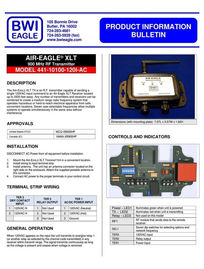
BWI Eagle
BWI Eagle AIR-EAGLE XLT Product information bulletin
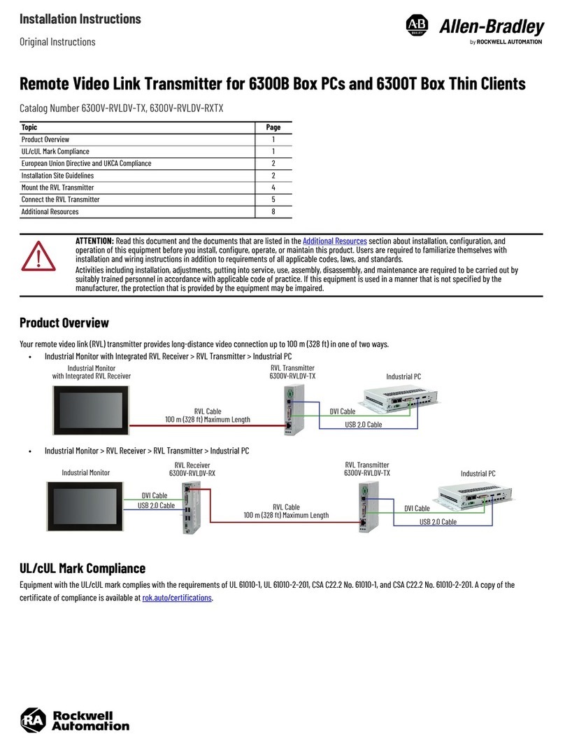
Allen-Bradley
Allen-Bradley 6300V-RVLDV-TX installation instructions

AUREL
AUREL TX1-HCS-433 instruction manual

