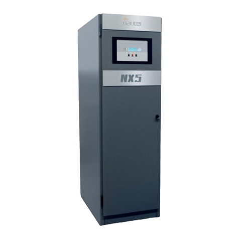
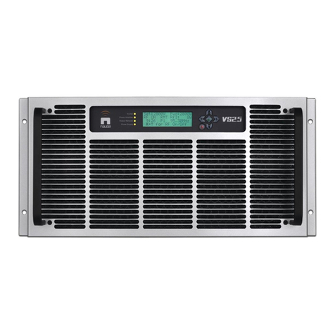
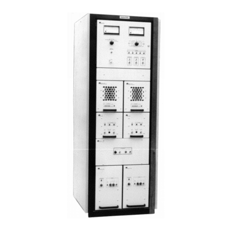
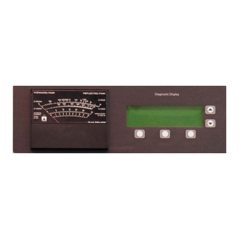
Nautel J1000 User manual

J1000
1,000 Watt
AM Broadcast
Transmitter
Installation and Operation Manual
Issue 7.0 ..................................03 June 2020
Nautel Limited
10089 Peggy's Cove Road,
Hackett's Cove, NS, Canada B3Z 3J4
T.877 6 nautel (628835) or +1.902.823.2233
F.+1.902.823.3183 info@nautel.com
U.S. customers please contact:
Nautel Inc.
201 Target Industrial Circle, Bangor ME 04401
T.877 6 nautel (628835) or +1.207.947.8200
www.nautel.com
Copyright 2020 NAUTEL. All rights reserved.


J1000 Installation and Operation Manual Issue 7.0
Warranty Information Page 1
Warranty
by Nautel Limited/Nautel Inc. (herein after referred to as Nautel)
Nautel guarantees all mechanical and electrical parts of Nautel Transmitters for a period of
forty-eight months, and all other Nautel manufactured equipment (including Importers and
Exporters) for a period of twelve months from date of shipment, provided the equipment has
been installed, operated and maintained in accordance with Nautel’s recommendations, and the
equipment has not been misused, neglected or modified. Nautel’s liability is limited, at the
absolute discretion of Nautel, to repairing or replacing returned equipment that to the
satisfaction of Nautel has been found defective.
Warranty for third-party items is provided by the Original Equipment Manufacturer. Exercise of
such warranty shall be between the Buyer and the Third-Party.
1. Properly qualified technical personnel must install, maintain, and repair the equipment in accordance with
Nautel recommendations and good engineering practice.
2. A "Part Failure" shall be deemed to have occurred when the part has become defective, or does not have the
characteristics required for the specified equipment performance:
a. when the equipment is operated within the design parameters, and
b. when the equipment is installed and adjusted according to Nautel's prescribed procedures as stated in the
instruction manual.
3. Nautel shall provide replacements for all "Parts" to the Buyer when they become defective during the warranty
period, and upon the return of the defective part. Replacement parts warranty to be 90 days or end of original
warranty; whichever comes first.
4. If the Buyer receives a replacement module, as part of Nautel’s module exchange program, the old module
must be returned to Nautel within 30 days of receipt of the new module, at the buyers expense. If the old
module is not received after 30 days, the customer will be invoiced. The buyer is responsible for installing the
replacement/repaired module in the transmitter.
5. In the event that a "Part" fails during the warranty period and causes damage to a subassembly which cannot
be readily repaired in the field, the entire subassembly so damaged may be returned to Nautel for repair. The
repairs will be made without charge to the Buyer.
6. Written authorization must be obtained before returning any equipment or goods for any reason. Equipment or
goods returned under this warranty shall be delivered to Nautel's premises at the Buyer’s expense. Where no-
charge warranty replacements or repairs are provided under items 2, 3, 4, or 5, Nautel will pay that part of the
shipping costs incurred in returning the part/assembly to the Buyer. Note: the Buyer is responsible for any and
all import fees, duties or taxes.
7. Nautel does not warrant or guarantee, and will not be liable for:
a. defects or failures caused in whole or in part by abuse, misuse, unauthorized repair attempts,
unauthorized alteration or modification of the equipment;
b. equipment built to customer specifications that is later found not to meet customer needs or expectation;
c. performance of equipment when it is used in combination with other equipment not purchased, specified,
or approved by Nautel;
d. damages and performance limitations due to outside forces such as lightning, excessive heat or cold,
excessive AC surges or high corrosive environments;
e. changes made by personnel other than Nautel authorized personnel, including charges incurred; and
f. for any costs for labor performed by the customer without Nautel’s prior written approval.
8. Nautel does not warrant that software:
a. is free of errors, bugs or defects;
b. will be compatible with third party software;
c. results, output or data provided through or generated by the software are accurate, complete, or reliable;
and
d. errors found will be corrected.
J1000 Installation and Operation Manual Issue 7.0
Warranty Information Page 2
9. Nautel shall have the right and shall be provided full access to investigate whether failures have been caused by factors
beyond its control.
10. In no event shall Nautel be liable for any consequential damages arising from the use of this equipment
11. This warranty is in lieu of all other express warranties of Nautel, whether express or implied, and Nautel does not assume,
nor is any other person authorized to assume on Nautel's behalf, any other obligation or liability.
12. Third party items ordered, the guarantee/warranty of these items will be from the manufacturer of these items. Exercise of
such warranty shall be between the Buyer and the third party provider.
13. Nautel provides telephone and email support for its products for the life of the product at no charge. After the warranty period,
parts and on-site support for the equipment are offered at a rate to be determined upon request.
Customer Service Notice
A ‘Technical Assistance’ and ‘Plug-in Module Exchange’ service is available to Nautel users.
All equipment being returned to Nautel and all requests for repairs or replacements should be marked with a Nautel provided
RMA number and addressed to the appropriate Nautel facility:
Nautel Limited
10089 Peggy's Cove Road
Hackett's Cove, NS, Canada B3Z 3J4
Tel: 902-823-2233/Fax: 902-823-3183
24 Hour Answerin
g
Service
(
902
)
823-3900
Nautel Inc.
201 Target Industrial Circle
Bangor, ME, USA 04401
Tel: 207-947-8200/Fax: 207-947-3693
Toll Free
(
877
)
662-8837

J1000 Installation and Operation Manual Issue 7.0
Factory Support Page 1
Factory Support
TECHNICAL ASSISTANCE
Nautel's field service department provides telephone technical assistance 24 hours a day, seven days a week. Requests via facsimile
or e-mail received after Nautel's normal working hours are responded to the next working day. Contact the appropriate field service
centre from the following:
U.S.A. customers use: Nautel Incorporated T.+1.207.947.8200 (24 hours) or 877 6 nautel (628835)
201 Target Industrial Circle F.+1.207.947.3693
Bangor, Maine 04401
All other customers use: Nautel Limited T. +1.902.823.3900 (24 hours) or 877 6 nautel (628835)
10089 Peggy’s Cove Road, F. +1.902.823.3183
Hackett’s Cove, NS, Canada E-Mail support@nautel.com
B3Z 3J4 Web www.nautel.com
MODULE EXCHANGE SERVICE
In order to provide Nautel customers with fast and efficient service in the event of a problem, Nautel operates a factory rebuilt
module exchange service which takes full advantage of the high degree of module redundancy in Nautel equipment. This module
exchange service is operated from Nautel’s factory in Bangor, Maine and Hackett’s Cove, Nova Scotia. These two locations allow
us to provide a quick turn around service to keep our customers on the air. During the transmitter’s warranty period, up to 48
months from shipment, repair and exchange of modules is at no charge to the customer. When the warranty has expired, a charge
of 80% of the list price for all exchanged modules is made. If the faulty module is returned to Nautel within 30 days, a credit is
issued reducing this charge by one half to 40% of the list price. U.S.A. customers are required to contact our Bangor, Maine
facility. Canadian and overseas customers should contact our Nova Scotia, Canada facility.
EQUIPMENT BEING RETURNED TO NAUTEL
For all equipment being returned to Nautel and all requests for repairs or replacements:
Obtain an RMA number from Nautel (you must have an RMA number to return equipment)
Mark the item as 'field return'
Mark the item with the RMA number assigned by Nautel
Address the item to the appropriate Nautel facility
Please provide complete and accurate information regarding the equipment being returned. This will ensure Nautel can provide
prompt attention so that replacement parts can be shipped as soon as possible. Refer to the nameplate on the transmitter and/or the
appropriate module/assembly to obtain name, type, part and serial number information. Refer to the parts list of this manual or the
appropriate service instruction manual for additional ordering information.
The following information should accompany each request:
* Model of Equipment
* Serial number of Equipment
* Name of Part/Assembly
Serial number of Part/Assembly
* Complete reference designation of Part/Assembly
* Nautel's part number of Part/Assembly
* OEM's part number of Part/Assembly
Number of hours in Use
Nature of defect
* Return shipping address
* Denotes minimum information required to order spare/replacement parts


J1000 Installation and Operation Manual Issue 7.0
Safety Information Page 1
SAFETY
Symbols
The following are general definitions for safety symbols used on the equipment or in the Installation and
Operation Manual:
DANGER – HIGH VOLTAGE
Indicates dangerous voltages (in excess of 72 volts), capable of causing a fatal
electrical shock, are present on or near parts bearing this label.
GROUND (EARTH)
Used with wiring terminals to indicate the terminal must be connected to earth ground
before operating equipment. If power is supplied without grounding the equipment,
there is a risk of receiving a severe or fatal electrical shock. Also used on electrical
schematics to indicate a part that is connected to earth ground.
GROUND (PROTECTIVE or SAFETY)
Used with protective (safety) conductor terminals to indicate the terminal must be
connected to ground before operating the equipment. If power is supplied without
grounding the equipment, there is a risk of receiving a severe or fatal electrical
shock.
WARNING A WARNING denotes a hazard. It identifies an operating procedure or condition
which, if not strictly observed or adhered to, could result in injury or death to
personnel. Throughout the Installation and Operation Manual, a WARNING will
immediately precede the text to which it applies.
CAUTION A CAUTION denotes a hazard. It identifies an operating procedure or condition
which, if not strictly observed or adhered to, could result in damage to, or destruction
of the equipment. Throughout the Installation and Operation Manual, a CAUTION
will immediately precede the text to which it applies.
NOTE A NOTE denotes important information pertaining to an operating procedure,
condition, statement, etc., which is essential to highlight. A NOTE may precede or
follow the text to which it applies.

Issue 7.0 J1000 Installation and Operation Manual
Page 2 Safety Information
SAFETY
Toxic Hazard Warning
There may be devices used in this equipment containing beryllium oxide ceramic, which is non-
hazardous during normal device operation and under normal device failure conditions. These devices
are specifically identified in the equipment parts list(s) by including ‘BeO’ in the part’s description.
DO NOT cut, crush or grind devices because the resulting dust may be HAZARDOUS IF INHALED.
Unserviceable devices should be disposed of as harmful waste.


NOTICE FOR HD RADIO USERS ONLY
SALE OR DISTRIBUTION OF THIS DEVICE REQUIRES A
LICENSE FROM IBIQUITY DIGITAL CORPORATION.


J1000 Installation and Operation Manual Jun 03.20
Contents Page
1 GENERAL INFORMATION 1-1
1.1 INTRODUCTION 1-1
1.2 PURPOSE AND SCOPE OF MANUAL 1-1
1.3 PURPOSE OF EQUIPMENT 1-1
1.4
TEST EQUIPMENT 1-1
2 PREPARATION FOR USE AND INSTALLATION 2-1
2.1 PREPARATION FOR USE 2-1
2.1.1 Transmitter Weights and Dimensions 2-1
2.1.2 Transmitter Clearances 2-2
2.1.3 Cooling 2-2
2.1.4 Heating 2-2
2.1.5 Work Area 2-2
2.1.6 Ac Power Switch 2-2
2.1.7 Lightning Protection 2-2
2.1.8 Station Reference Ground2-2
2.1.9 AC Power Source 2-2
2.1.9.1 Ac Wiring 2-2
2.1.10 Antenna Feed Cable 2-3
2.1.11 Antenna/RF Output Disconnect 2-3
2.1.12 Antenna Tower 2-3
2.1.13 External Control/Monitor Wiring 2-3
2.1.14 Electrical Power 2-3
2.1.14.1 Voltage Stability 2-3
2.1.14.2 Power Consumption 2-4
2.1.14.3 External Ac Switching 2-4
2.1.15 Antenna System 2-4
2.1.15.1 Antenna System – Digital Modulation 2-4
2.1.15.2 RF Feed Cable 2-4
2.1.15.3 Interface Protection Option 2-4
2.1.16 External RF Drive Source 2-5
2.1.16.1 Carrier Frequency Signal 2-5
2.1.16.2 10 MHz Frequency Reference 2-5
2.1.17 Internal/External RF Driver Source Selection 2-5
2.1.18 Modulating Audio 2-5
2.1.18.1 Conventional AM Broadcast 2-6
2.1.18.2 Digital Operation (External Phase Component) 2-6
2.1.18.3 Digital Operation HD Radio 2-6
2.1.19 Audio Pass Band Selection 2-6
2.1.20 External Interlocks 2-7
2.1.21 Remote Control Circuits 2-7
2.1.21.1 On/Off Control 2-8
2.1.21.2 Main Exciter Selection 2-8
2.1.21.3 Preset Power Level Selection 2-8

J1000 Installation and Operation Manual Jun.03.20
Contents Page
2.1.21.4 Power Level Adjust Select 2-8
2.1.21.5 System Reset 2-9
2.1.21.6 Auto/Manual 2-9
2.1.22 Other Remote Controls 2-9
2.1.22.1 PDM (RF) Inhibit Control 2-9
2.1.23 Serial Port2-9
2.1.24 RF Performance Monitoring 2-9
2.1.24.1 RF Monitor Sample 2-9
2.1.24.2 Forward Power Level 2-11
2.1.24.3 Reflected Power Level 2-11
2.1.24.4 B+ Volts Sample 2-11
2.1.24.5 Total Dc Current Sample 2-11
2.1.25 Remote Alarm Indications 2-11
2.1.25.1 Exciter Fail Alarm 2-11
2.1.25.2 Battery Alarm 2-11
2.1.25.3 High VSWR Alarm 2-11
2.1.25.4 Shutdown/Cutback Alarm 2-11
2.1.25.5 Changeover Alarm 2-12
2.1.25.6 Modulation Protection Alarm 2-12
2.1.25.7 Pwr Module Fail Alarm 2-12
2.1.25.8 Low Ac Alarm 2-12
2.1.25.9 External Interlock Alarm 2-12
2.1.25.10 LVPS Fail Alarm 2-12
2.1.26 Remote Status Indications 2-12
2.1.26.1 Remote Control Status 2-12
2.1.26.2 RF On Status 2-12
2.1.26.3 Exciter B Status 2-12
2.1.26.4 Auto Status 2-12
2.1.26.5 RF Power Level Status 2-13
2.1.27 Parts Supplied by Nautel 2-13
2.1.27.1 Reject Load 2-13
2.1.28 Parts Not Supplied by Nautel 2-13
2.1.29 Test Equipment and Special Tools 2-13
2.1.30 Available Options 2-14
2.1.30.1 Standby Exciter Option 2-14
2.1.30.2 User-Supplied Cabinet Option 2-14
2.1.30.3 Nautel Cabinet Option 2-14
2.1.30.4 Spares Kit Option 2-14
2.1.30.5 Interface Protection Unit Option 2-14
2.1.30.6 Frequency Change Kit Option 2-14
2.1.30.7 CE Kit Option 2-15
2.2 INSTALLATION 2-15
2.2.1 Accepting the Shipment 2-15
2.2.2 Unpacking Instructions 2-15
2.2.3 Visual Inspection 2-16
2.2.4 RF Output Connector 2-20
2.2.5 Cabinet Installation 2-20
2.2.6 Installing RF Power Modules 2-22
2.2.7 Interconnect
Wiring 2-22

J1000 Installation and Operation Manual Jun 03.20
Contents Page
2.2.8 Ac Power Switching Assembly 2-22
2.2.9 Installing Ac Power Wiring 2-22
2.2.10 RF Feed Cable 2-23
2.2.10.1 7/8-Inch RF Output Connection 2-23
2.2.11 Reject Load 2-23
2.2.12 Interface Protection Unit 2-24
2.2.12.1 RF Output Connector 2-25
2.2.12.2 Mounting 2-25
2.2.12.3 Ac Circuit Breaker and Fusing 2-25
2.2.12.4 Ground Stud 2-25
2.2.12.5 Remote Control/Monitor Wiring 2-25
2.2.13 Station Reference Ground2-26
2.2.14 Determining Control/Monitoring
Requirements 2-26
2.2.15 External Control Wiring 2-26
2.2.16 Internal/External RF Drive Source 2-26
2.2.17 Adjusting the Spark Gap 2-27
2.3 COMMISSIONING PROCEDURES 2-29
2.3.1 Precautions 2-29
2.3.2 Turn-On Prerequisites 2-29
2.3.3 Initial Turn-On 2-30
2.3.4 Placing J1000 On-Air 2-31
3 OPERATING INSTRUCTIONS 3-1
3.1 INTRODUCTION 3-1
3.1.1 Precautions 3-1
3.2 EMERGENCY SHUTDOWN 3-1
3.2.1 Turn Off RF Output 3-1
3.2.2 Complete Shutdown 3-1
3.3 EXTERNAL SAFETY INTERLOCK 3-2
3.4 ELECTROSTATIC DISCHARGE PROTECTION 3-2
3.4.1 Discharging of Personnel 3-2
3.4.2 Handling/Storage 3-2
3.4.3 Tools/Test Equipment3-2
3.4.4 Stress Current Protection 3-2
3.5 CONTROLS AND INDICATORS 3-3
3.5.1 Exciter Front Panel 3-3
3.5.2 Remote Interface PWB 3-3
3.5.3 RF Synthesizer PWB 3-3
3.5.4 Miscellaneous Exciter 3-3
3.5.5 RF Power Module 3-3
3.6 DIAGNOSTIC DISPLAY 3-14
3.6.1 Pushbutton Switches 3-14
3.6.2 Main Screen 3-14
3.6.2.1 Transmitter Status Bar 3-14

J1000 Installation and Operation Manual Jun.03.20
Contents Page
3.6.3 Viewing
Faults 3-16
3.6.4 Adjusting RF Output Power and Setting Power Preset Levels 3-16
3.6.5 Exciter Control 3-17
3.6.6 Viewing Events Log 3-18
3.6.7 Scheduling Pre-Set Power Levels 3-19
3.6.8 Setting Real Time Clock 3-20
3.6.9 Changing Factory Calibrated Settings 3-20
3.6.9.1 Calibrate Meters 3-21
3.6.9.2 Set Thresholds 3-22
3.6.9.3 Maximum Allowable Output Gain 3-22
3.6.9.4 Use Factory Settings 3-22
3.6.10 Viewing Software Version 3-23
3.6.11 NxLink Configuration 3-23
3.6.12 Selecting Metered Parameters 3-24
3.6.13 Module Check 3-25
3.6.14 Battery Status 3-25
4 TESTING AND ADJUSTMENT 4-1
4.1 INTRODUCTION 4-1
4.2 OPERATING PRECAUTIONS 4-1
4.3 FUNCTIONAL TESTS 4-1
4.3.1 General 4-1
4.3.2 Test Equipment Required 4-2
4.3.3 Test Prerequisites 4-2
4.3.4 Initial Turn-On 4-4
4.3.5 Standard Adjustments 4-4
4.3.5.1 Modulation Checks 4-4
4.3.6 Non-Standard Adjustments 4-5
4.3.6.1 RF Drive Symmetry 4-5
4.3.6.2 Exciter Gain (Dual Exciter J000s Only) 4-7
4.3.6.3 Modulation Peak Limiting 4-7
4.3.6.4 Audio Dump 4-7
4.3.6.5 Dc Current Cutback 4-9
5 SYSTEM LEVEL TROUBLESHOOTING 5-1
5.1
GENERAL 5-1
5.2
SCHEDULED
MAINTENANCE 5-1
5.2.1 Cleaning the J1000 5-1
5.2.2 Checking Hardware 5-1
5.2.3 Battery Replacement 5-2
5.3 CORRECTIVE MAINTENANCE 5-2
5.3.1 On-Air Troubleshooting 5-2
5.3.1.1 Remote Troubleshooting 5-2
5.3.1.2 Local Troubleshooting 5-2
5.3.2 Off-Air Troubleshooting 5-2

J1000 Installation and Operation Manual Jun 03.20
Contents Page
5.4 ELECTROSTATIC PROTECTION 5-3
5.4.1 Discharging of Personnel 5-3
5.4.2 Handling/Storage 5-3
5.4.3 Tools/Test Equipment5-3
5.4.4 Stress Current Protection 5-3
5.5 TROUBLESHOOTING FRONT PANEL ALARMS 5-4
5.5.1 Zeroing Power to Attempt an Alarm Reset 5-6
5.6
OPERATING WITH DEFECTIVE OR MISSING
RF POWER MODULE 5-11
5.7 RF POWER MODULE FAULT ISOLATION 5-12
5.8 REPLACING AN RF POWER MODULE 5-12
5.8.1 RF Power Module Removal 5-12
5.8.2 RF Power Module Installation 5-13
5.9 EXCITER/CONTROL ASSEMBLY PWBREPLACEMENT 5-14
5.9.1 Exciter Interface PWB and Interconnecting
PWB Replacement 5-14
5.9.1.1 RF Synthesizer PWB Removal/Replacement 5-15
5.9.1.2 Interphase PDM Driver PWB Removal/Replacement 5-16
5.9.1.3 Exciter Interface PWB Removal/Replacement 5-16
5.9.2 Remote Interface PWB Replacement 5-17
5.9.3 Power Supply Replacement 5-17
5.9.4 LVPS Buck Converter PWB Replacement 5-17
5.10
COOLING FAN REPLACEMENT 5-18
5.11 FORWARD/REFLECTED POWER PROBE PWB REPLACEMENT 5-19
5.12 POWER MODULE FAN REPLACEMENT 5-19
List of Tables
1-1 Recommended Site Test Equipment 1-3
2-1 Transmitter Weights and Dimensions 2-1
2-2 Audio Filter Switch Settings 2-6
2-3 Altitude Scale Factor 2-28
3-1 Exciter Panel – System Diagram Controls and Indicators 3-6
3-2 Exciter Panel – Control Section Controls and Indicators 3-8
3-3 Remote Interface PWB Controls and Indicators 3-10
3-4 RF Synthesizer PWB Controls and Indicators 3-12
3-5 Miscellaneous Exciter Controls and Indicators 3-13
3-6 RF Power Modules Controls and Indicators 3-13
5-1 Troubleshooting and Replacement Tips 5-8

J1000 Installation and Operation Manual Jun.03.20
Contents Page
List of Figures/Drawings
1-1 J1000 Transmitter 1-2
2-1 Single Ended Input Selected 2-7
2-2 Differential Input Selected 2-8
2-3 J1000 External Input/Output Interface2-10
2-4 Dimensional Information - J1000Transmitter without Cabinet &
Front Grille 2-17
2-5 Dimensional Information - J1000Transmitter with Nautel Cabinet2-18
2-6 Recommended Installation for J1000 Transmitter 2-19
2-7 Assembly/Installation Considerations for User Supplied Cabinet2-21
2-8 Interface Protection Assembly 2-24
2-9 RF Output Spark Gap Location 2-27
2-10 RF Power Module Current versus RF Output Power 2-30
2-11 Buffered Dc Current versus RF Output Power 2-31
3-1 J1000 Exciter Front Panel (Primary User Interface) 3-4
3-2 J1000 Exciter Front Panel - System Diagram Section 3-5
3-3 J1000 Exciter Front Panel - Control Section 3-7
3-4 Assembly Detail - Part of Remote Interface PWB (NAPI85/01A) 3-9
3-5 Assembly Detail - RF Synthesizer PWB (NAPE70F/01) 3-11
3-6 Diagnostic Display - Main Screen 3-14
3-7 Diagnostic Display – Main Menu Screen 3-14
3-8 Flow Diagram – Diagnostic Display Menu Functions 3-15
4-1 Exciter/Control Assembly (Unit 1) 4-3
4-2 RF Power Module (Left-Hand Side View) 4-6
4-3 RF Output with Positive Peak Limiting 4-8
4-4 Modulated RF Output with Audio Dump Distortion Adjustment 4-8
5-1 Partial Rear View of J1000 (showing RF Power Modules) 5-11
5-2 Removing Cooling Fans from Exciter/Control Assembly 5-18
Appendices
A Site Evaluation Checklist A-1

J1000 Installation and Operation Manual Jun 03.20
Control Record
Issue Date Reason
7.0 03 June 2020 Release 7 of J1000 (NARA40F)

Other manuals for J1000
2
Table of contents
Other Nautel Transmitter manuals

Nautel
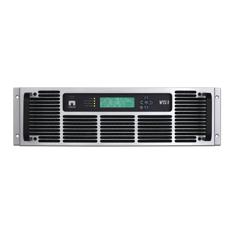
Nautel VS1 User manual

Nautel
Nautel ND500II User manual

Nautel
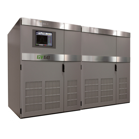
Nautel GV60 Programming manual

Nautel
Nautel GV5 Manual

Nautel
Nautel VS300 User manual

Nautel
Nautel ND500II-113-x21 User manual

Nautel
Nautel NV40 Programming manual

Nautel
Nautel NV5LT Programming manual

Nautel
Nautel FM10011 User manual

Nautel
Nautel NX50 User manual

Nautel
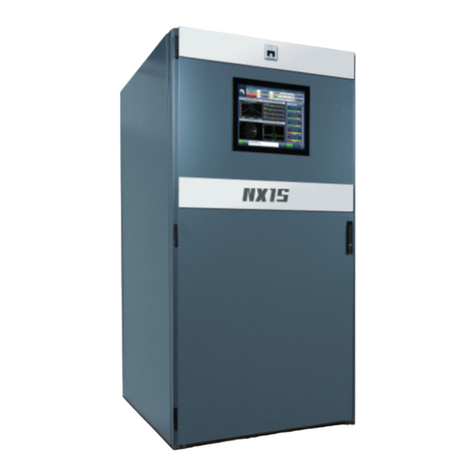
Nautel NX15 User manual

Nautel
Nautel ND500II Owner's manual

Nautel
Nautel NV20LT User manual

Nautel
Nautel VS1 User manual

Nautel
Nautel J1000 Operating instructions

Nautel
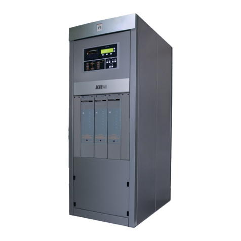
Nautel XR12 Programming manual

Nautel
Nautel NX200 User manual

Nautel
Nautel NV7.5 User manual

Nautel
Nautel NV30LT-N Manual

Nautel
Nautel NV30 User manual