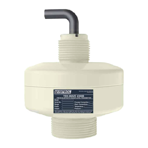
Tek-Trol TEK-WAVE 4300B User manual

Technology Solutions
Instruction Manual
Document Number: IM-4300B
www.tek-trol.com
FMCW Bluetooth Radar Level Transmitter
TB
EK-WAVE 4300

www.tek-trol.com
NOTICE
Read this manual before working with the product. For personal and system safety, and for optimum product performance, make sure you thoroughly understand the contents before installing, using, or maintaining this product.
For technical assistance, contact
Customer Support
796 Tek-Drive
Crystal Lake, IL 60014
USA
Tel: +1 847 857 6076
© COPYRIGHT Tek-Trol LLC 2022
No part of this publication may be copied or distributed, transmitted, transcribed, stored in a retrieval
system, or translated into any human or computer language, in any form or by any means, electronic,
mechanical, manual, or otherwise, or disclosed to third parties without the express written permission.
The information contained in this manual is subject to change without notice.

TechnologySolutions
Instruction Manual
Tek-Wave 4300B
www.tek-trol.com
1
Table ofContents
1Safety Instructions ...........................................................................................................................2
1.1 Intended Use ........................................................................................................................................2
1.2 Safety Instructions from the Manufacturer ............................................................................................2
1.2.1 Disclaimer..................................................................................................................................................... 2
1.2.2 Product Liability and Warranty .................................................................................................................... 2
1.2.3 Information Concerning the Documentation .............................................................................................. 2
1.3 Safety Precautions ................................................................................................................................ 2
1.4 Packaging, Transportation and Storage.................................................................................................. 3
1.4.1 Packaging ..................................................................................................................................................... 3
1.4.2 Transportation ............................................................................................................................................. 3
1.4.3 Storage ......................................................................................................................................................... 3
1.4.4 Nameplate.................................................................................................................................................... 3
2Product Description..........................................................................................................................4
2.1 Introduction .........................................................................................................................................4
2.2 Working Principle .................................................................................................................................4
2.3 Specifications........................................................................................................................................5
2.4 Dimension Drawings .............................................................................................................................5
2.4.1 Mounting Brackets....................................................................................................................................... 6
2.5 Model Chart..........................................................................................................................................7
3Installations .....................................................................................................................................8
3.1 Mounting.............................................................................................................................................. 8
3.1.1 General mounting conditions ...................................................................................................................... 8
3.1.2 Stirring Fan in Vessel.................................................................................................................................... 9
3.1.3 Reduction of Interference Echoes ............................................................................................................... 9
3.1.4 Mounting with Bracket .............................................................................................................................. 10
4Electrical Connection...................................................................................................................... 10
4.1 Wiring Connection .............................................................................................................................. 11
5Operations (Setup with Smartphone/Tablet (Bluetooth)or Modbus Software) ................................ 11
5.1 Bluetooth Setup (Android Only) .......................................................................................................... 11
5.2 Setup.................................................................................................................................................. 12
5.2.1 Main Menu................................................................................................................................................. 12
5.2.2 Setting Parameters..................................................................................................................................... 12
5.3 Modbus Software Setup...................................................................................................................... 15
6Menu Tree ..................................................................................................................................... 21

TechnologySolutions
Instruction Manual
Tek-Wave 4300B
www.tek-trol.com
2
1Safety Instructions
1.1 Intended Use
Tek-Wave 4300B FMCW Bluetooth Radar Level Transmitter is widely used to measure the level of
storage tanks, open basins, pump or lift stations, water and wastewater treatment plants.
1.2 Safety Instructions from the Manufacturer
1.2.1 Disclaimer
The manufacturer will not be held accountable for any damage that happens by using its product,
including, but not limited to, direct, indirect, or incidental and consequential damages. Any product
purchased from the manufacturer is warranted by the relevant product documentation and our Terms
and Conditions of Sale. The manufacturer has the right to modify the content of this document of any
time with any reason without prior notice and will not be answerable for the possible consequence
of changes.
1.2.2 Product Liability and Warranty
The operator shall have authority for the suitability of the device for the specific application. The
manufacturer accepts no accountability for the consequences of misuse by the operator. A wrong
installation or operation of the devices (systems) will cause the warranty to be void. The respective
Terms and Conditions of Sale, which forms the basis for the sales contract, shall also apply.
1.2.3 Information Concerning the Documentation
To prevent any injury to the operator or damage to the device, it is essential to read the information
in this document and the applicable national standard safety instructions. This operating manual
consists of all the information that is required in various stages, such as product identification,
incoming acceptance and storage, mounting, connection, operation and commissioning,
troubleshooting, maintenance, and disposal.
1.3 Safety Precautions
You must read these instructions carefully before installing and commissioning the device. These
instructions are an essential part of the product and must be kept for future reference. Only by
observing these instructions, optimum protection of both personnel and the environment, as well as
safe and fault-free operation of the device can be ensured. For additional information that is not
discussed in this manual, contact the manufacturer.
The following safety symbol marks are used in this operation manual and on the instrument.
WARNING
Indicates a potentially hazardous situation which, if not avoided, could result in
death or severe injury
CAUTION
Indicates a potentially hazardous situation which, if not avoided, may result in
minor or moderate injury. It may also be used to alert against unsafe practices.

TechnologySolutions
Instruction Manual
Tek-Wave 4300B
www.tek-trol.com
3
NOTE
Indicates that operating the hardware or software in this manner may damage it
or lead to system failure.
1.4 Packaging, Transportation and Storage
1.4.1 Packaging
The original package consists of
1. Tek-Wave 4300B FMCW Bluetooth Radar Level Transmitter
2. Documentation
NOTE
Unpack and check the contents for damages or sign of rough handling. Report
damage to the manufacturer immediately. Check the contents against the packing
list provided.
1.4.2 Transportation
•Avoid impact shocks to the device and prevent it from getting wet during transportation.
•Verify local safety regulations, directives, and company procedures with respect to hoisting,
rigging, and transportation of heavy equipment.
•Transport the product to the installation site using the original manufacturer’s packing
whenever possible.
1.4.3 Storage
If this product is to be stored for an extended period of time before installation, take the following
precautions:
•Store your product in the manufacturer’s original packing used for shipping.
•The storage location should comply with the following requirements:
oFree from rain and water
oFree from vibration and impact shock
oAt room temperature with minimal temperature and humidity variation
•Before storing a used flow meter, remove any fluid from the flow meter line completely.
Properties of the instrument can change when stored outdoors.
1.4.4 Nameplate
The nameplate lists the order number and other important information, such as design details and
technical data.
NOTE
Check the device nameplate to ensure that the device is delivered according to your
order. Check for the correct supply voltage printed on the nameplate.

TechnologySolutions
Instruction Manual
Tek-Wave 4300B
www.tek-trol.com
4
2Product Description
2.1 Introduction
Tek-Wave 4300B FMCW Bluetooth Radar Level Transmitter continuously measures different liquids and
solids levels in simple applications with lower pressure and temperature ranges demands. It is mainly
suitable for water treatment, pumping stations, rain overflow basins, and level monitoring. In bulk
solids applications, the sensors are used in small bulk solids silos or open containers.
The non-contact 80GHz radar transmitter includes Bluetooth technology for commissioning, operation
and maintenance, which reduces cost and time. Every Bluetooth®-enabled smartphone or tablet can
display output signal through an app (Android). Simple, safe and secure wireless remote access Radar
Level Transmitter is suitable for installation in difficult places. Its unique radar chip design makes it the
most compact radar that perfectly fits in limited space applications. Its full PVDF body resists outdoor
conditions, sealed wiring and fully potted electronics eliminate water ingress and allows operation
under harsh environmental conditions. Perfect application fit for water & wastewater and utilities in all
industries
Fig 1: Tek-Wave 4300B FMCW
Bluetooth Radar Level Transmitter
2.2 Working Principle
The Tek-Wave 4300B FMCW Bluetooth Radar Level Transmitter uses 80GHz Frequency Modulated
Continuous Wave. The FMCW radar emits a high-frequency signal that increases linearly during the
measurement phase (called the frequency sweep). The signal is emitted, reflected from the measuring
surface and received with a time delay (t).
Delay Time (t)= 2D/C
Where,
D is the distance to the product surface.
C is the speed of light in the gas above the product.
The difference Δf is calculated from the actual transmit frequency and the receive frequency for further
signal processing. This difference is directly proportional to the distance.

TechnologySolutions
Instruction Manual
Tek-Wave 4300B
www.tek-trol.com
5
2.3 Specifications
Accuracy
±2mm
Measuring Range
45ft
Repeatability
±1mm
Frequency
76 to 81GHz
Resolution
1mm
Response Time
<2S
Process Temperature
-40°F to 176°F (-40°C to 80°C)
Process Pressure
-14.5 to 40psi (-1 to 3bar)
Beam Angle
8°
Process Connection
1-1/2" Male NPT
Electrical Connection
3/4" Male NPT with 15' lead wire
Digital Output
Bluetooth, HART, Modbus RS-485
Power
<0.5W (Power supply required 24VDc with minimum 25mA)
Analog Output
4-20mA (2-wire)
Enclosure & Ratings
IP68
Approvals
CE
2.4 Dimension Drawings
Fig 2: Front View

TechnologySolutions
Instruction Manual
Tek-Wave 4300B
www.tek-trol.com
6
2.4.1 Mounting Brackets
Fig 3: Mounting Bracket Side Angle
Fig 4: Mounting Bracket Back Angle
Fig 5: Mounting Bracket Top Angle
13”
21.5”
8”
3/₈”
17.25”
4” 4”
2”
2.25”
6”2.25”
3.5”
6”
1.5” NPT
2”

TechnologySolutions
Instruction Manual
Tek-Wave 4300B
www.tek-trol.com
7
Fig 6: Mounting Bracket
2.5 Model Chart
Example
Tek-Wave
4300B
01 A 01 B 015 A 01 A # Tek-Wave 4300B-01-A-01-B-015-A-01-A
Series
Tek-Wave
4300B
FMCW Bluetooth Radar Level Transmitter
Output
01
18 to 36 VDC
Process
Connection
A 1-1/2" Male NPT
X
Special
Electrical
Connection 01
3/4" Male NPT
Range
B
45 Feet
Cable Length
015
15'Cable
Analog Output
A
4 to 20mA
Digital Output
01
Bluetooth, HART, Modbus RS-485
Enclosure &
Ratings
A IP68
Options
TAG
Tag
FC
Factory Configuration
BKT
Mounting Bracket
USB
Modbus Configuration Tool

TechnologySolutions
Instruction Manual
Tek-Wave 4300B
www.tek-trol.com
8
3Installations
This section covers instruction on installations and commissioning. Installations of the device must be
carried out by trained, qualified specialists authorized to perform such works.
CAUTION
•When removing the instrument from hazardous processes, avoid direct contact
with the fluid and the meter.
•All
installation must comply with local installation requirements and local
electrical code
3.1 Mounting
3.1.1 General mounting conditions
•The Tek-Wave 4300B should not be mounted closer than 8" (200mm) to the vessel wall.
•The Tek-Wave 4300B is not mounted in the center because interference can cause signal loss.
•The Tek-Wave 4300B is not mounted above the fill stream.
•A weather protection cover is recommended to protect the instrument from sun or rain.
•The radar antenna should be vertical to measure the media surface.
Fig 7: General Mounting Position

TechnologySolutions
Instruction Manual
Tek-Wave 4300B
www.tek-trol.com
9
3.1.2 Stirring Fan in Vessel
•If there is a stirring fan in the vessel:
oThe instrument should be mounted at 1/2 of the distance from the inner wall to the stirring
fan.
oCarry out false echo storage to reduce the interference from the stirring fan.
Fig 8: Mounting Position for Stirring Fan in Vessel
3.1.3 Reduction of Interference Echoes
Radar signals can spread by mounting metallic at a slope, which reduces the interference echoes.
Fig 9: Mounting Position for Interference Echoes Reduction

TechnologySolutions
Instruction Manual
Tek-Wave 4300B
www.tek-trol.com
10
3.1.4 Mounting with Bracket
•The instrument can also be mounted through a bracket with thread G1.
•The distance between the sensor and wall should not be closer than 8” (200mm).
Fig 10: Mounting with Bracket
4Electrical Connection
This section covers all electrical connection requirement. Electrical connection of the device must be
carried out by trained; qualified specialists authorized to perform such work by the installation site.
WARNING
•Connect all electrical cables when the power is switched off. If the device does
not have switch-off elements, then, overcurrent protection devices, lightning
protection and/or energy isolating devices must be provided by the customer.
•The device must be grounded to a spot in accordance with regulations in order
to protect personnel against electric shocks.
NOTE
When using the measuring device in hazardous areas, installation must comply with
the corresponding national standards and regulations and the Safety Instructions or
Installation or Control Drawings.

TechnologySolutions
Instruction Manual
Tek-Wave 4300B
www.tek-trol.com
11
4.1 Wiring Connection
Fig 11: Wiring Connection
5Operations (Setup with Smartphone/Tablet (Bluetooth)or Modbus Software)
5.1 Bluetooth Setup (Android Only)
•Install “Tek-Wave 4300B” on the google play store.
•Allow the APP to utilise the location and storage functions.
•Hold down the APP till it indicates “APP info”.
o”APP info”> “Permissions”>”Location”>”Allow”
o”APP info” >”Permissions”>”Storage”>”Allow”
•Start APP.
•Select Device “SENSOR 01”
Note: - If the 4300B is having any Alarm like HH or LL. the output current will be either 20.5 mA or 3.8 mA.at this
point the Bluetooth app will starts connect/disconnect or get hang to previous screen until the unit reaches to
normal operation.
Trouble shooting: Close the app and relaunch keep search for the 4300B unit repeatedly.
Wire Color
Function
Brown
Voltage +
White
Voltage – (4-20mA)
Green
Modbus RS485 A
Yellow
Modbus RS485 B
Gray
Ground
Table 1: Wire Description

TechnologySolutions
Instruction Manual
Tek-Wave 4300B
www.tek-trol.com
12
5.2 Setup
5.2.1 Main Menu
•You can find measuring distance, level and ratio on the main menu.
•Using Setting Menu, you can set the parameters.
5.2.2 Setting Parameters
Setting Parameters consist for sub menus

TechnologySolutions
Instruction Manual
Tek-Wave 4300B
www.tek-trol.com
13
5.2.2.1 Quick Setup
5.2.2.1.1 Set Measuring Range
•Please enter “Quick Setup” to set the measuring range.
•Write minimum and maximum range and press to save data.
•Write Tag number as per your application and press to save data.
•You can upload data from the device by pressing “Upload Data”.

TechnologySolutions
Instruction Manual
Tek-Wave 4300B
www.tek-trol.com
14
5.2.2.1.2 Check Echo Curve
•Enter menu with echo curve by entering “Level Confirm”.
•If you set a new measuring range and want to change the X range, please re-write the data
on the End and save it by Refresh Range
5.2.2.1.3 Create Fake Echo
•If there is an obstacle inside the tank that generates a fake echo, you will need to create a
fake echo.
•Please use “+” or “-” to move the line indicated by the arrow to set the fake echo position of
false echo and press behind Create and you will get new double echo curve.

TechnologySolutions
Instruction Manual
Tek-Wave 4300B
www.tek-trol.com
15
5.2.2.2 Basic Setup
•You can set the following parameters according to field conditions.
•You can also upload data from the device by “Upload Data”.
•For most applications, the device can work properly after the setup of the above two menus.
•For more menu information, please contact us, and you can also refer to the menu overview.
*Note: The distance between device and smartphone should be not more than 25’ to get better signal communication.
5.3 Modbus Software Setup
•Connect the 4300B to the 4300B-USB tool and power the 4300B.
Power Supply
+
_
PC
A
B
4300B-U SB
(Conguration Tool)
Brown
White
Yellow
Green

TechnologySolutions
Instruction Manual
Tek-Wave 4300B
www.tek-trol.com
16
•Launch the 4300B Modbus Program.
•When the program opens. Click Connect to Poll the 4300B.
•It will take the software a few moments to find the 4300B.

TechnologySolutions
Instruction Manual
Tek-Wave 4300B
www.tek-trol.com
17
•When the Modbus program connects to the 4300B, there will be two red flashing lights on the 4300B-
USB tool and a green Dot in the lower left side of the screen. The 4300B process data will appear on
the bottom of the screen.
•From the Quick Setup screen the Max and Min range can be set up the Max range is your 4mA and
the min range is you 20mA. You can also look at the Echo Curve on this screen.

TechnologySolutions
Instruction Manual
Tek-Wave 4300B
www.tek-trol.com
18
•In the Basic Setup screen the following parameter can be adjusted.
•In the System screen you can simulate a mA signal to make use you output is setup correctly at your
PLC or Scada.
Other manuals for TEK-WAVE 4300B
1
Table of contents
Other Tek-Trol Transmitter manuals

Tek-Trol
Tek-Trol TEK-B AR 3120B User manual

Tek-Trol
Tek-Trol TEK-WAVE 4300B User manual

Tek-Trol
Tek-Trol TEK-FLEX 4100A User manual

Tek-Trol
Tek-Trol Tek-Sound 4200B User manual

Tek-Trol
Tek-Trol TEK-BAR 3120B Series User manual

Tek-Trol
Tek-Trol TEK-WAVE 4300C User manual

Tek-Trol
Tek-Trol TEK-BAR 3800XP User manual

Tek-Trol
Tek-Trol Tek-Flex 4100A User manual

Tek-Trol
Tek-Trol TEK-W AVE 4300C User manual

Tek-Trol
Tek-Trol TEK-BAR 3800E User manual