AdvanceTec AT6701A User manual

User Manual
Pro Install Hands-Free Car Kit for
Kyocera™ DuraXT E4277
Car Kit Part # AT6701A consists of:
1. Part # AT8231A Speaker
2. Part # AT8256A Junction Box
3. Part # AT8230A Visor Microphone.
4. Part # AT8232A Power cable
5. Part # AT9299B PTT
6. Part # AT6700A Hands-free cradle
Optional Extras
1. Part #AT7107A Privacy Handset
2. Part # AT8428A Palm Mic.

2
Index
Page Details
3 Important PHONE Settings
3 Warnings
3 - 4 Speaker Installation
4 - 5 MicrophoneInstallation
5 – 6 MountingPTT
6 – 7 Power Cable Installation
8 Connecting Cables to Junction Box
9 Inserting and removinghandset from cradle
10 Car Ignition connection
10 Making Dispatch Call
10 Making/ReceivingHands-freecall
10 Call Waiting
10 - 11 ChargingBattery
11 OperatingSpecifications
OptionalExtras
11 - 12 Handset with Cradle
12 Palm Mic

3
IMPORTANT PHONE SETTINGS
Thefollowingarephonesettingsthatareneededforoperationwiththe
AdvanceTechandsfree:
1.Press>Settings>DCSettings>DirectConnectON
2.Press>Settings>DCSettings>HeadsetMode>Headsetbuttonstarts
DCcalls.[DCbutton].
3.Press>Settings>Others>Accessibility>TTY>TTYOff.
4.IncreaseorDecreasethehandsfreevolumemustbedonewhilephone
isconnectedtothehandsfreeandisonanactivecall.
Hands‐free Installation
Beforebeginningtheinstallationprocess,determinethebestlocationsfor
themountingoftheMountingBracket,Hand‐freeCradle,Push‐To‐Talk
(PTT)button,VisorMicrophone,SpeakerandJunctionBox.
Considerthefollowingguidelinewhenplanningtheinstallation:
DOuseallmountinghardwareprovided.
DOensurethatcablesarenotplacedunderstress.
DOfollowproper+and‐connections.
DOcrimpconnectorssecurely.
DONOTattachcomponentstoanypartofthevehiclethatisnot
rigidorissubjecttoexcessivevibration.
DONOTinstallcomponentsinareaswhererainorsnowcaneasily
getintothem,suchasnexttoavehiclewindow,whichmaybeleft
open.
DONOTdresscablesoversharpedgesthatcouldcausewearor
tearingofcableinsulation.
DONOTinstallcomponentsinlocationswheretheymight
interferewiththevehicleoperatororoperatingcontrols.
DONOTinstalltheHands‐freeCradlewhereitwillbedifficultfor
theoperatortoreach.
!WARNING
VEHICLESEQUIPPEDWITHAIRBAGS
Anairbaginflateswithgreatforce.DONOTplaceobjects,including
communicationsequipment,intheareaovertheairbagorintheairbag
deploymentarea.Ifthecommunicationequipmentisimproperlyinstalled
andtheairbaginflates,thiscouldcauseseriousinjury.
Itisrecommendedthattheinstallationofthevehiclecommunication
equipmentbeperformedbyaprofessionalinstaller/techniciantrainedin
therequirementsforsuchinstallations.Anairbag'ssize,shapeand
4
deploymentareacanvarybyvehiclemake,model,andfrontcompartment
configuration(forexample,benchseatvs.bucketseats).Contactthe
vehiclemanufacturer'scorporateheadquarters,ifnecessary,forspecificair
baginformationforthevehiclemake,model,andfrontcompartment
configurationinvolvedinyourcommunicationequipmentinstallation.
A. Speaker Installation
1.MounttheSpeakerbeneaththedashboard,onthepassenger'ssideof
thevehicle,outofthewayofthepassenger.DonotmounttheSpeaker
onthedashboardortherearwindowshelf.
2.TheSpeakershouldbelocatedmorethanfourfeetfromthejunction
box.
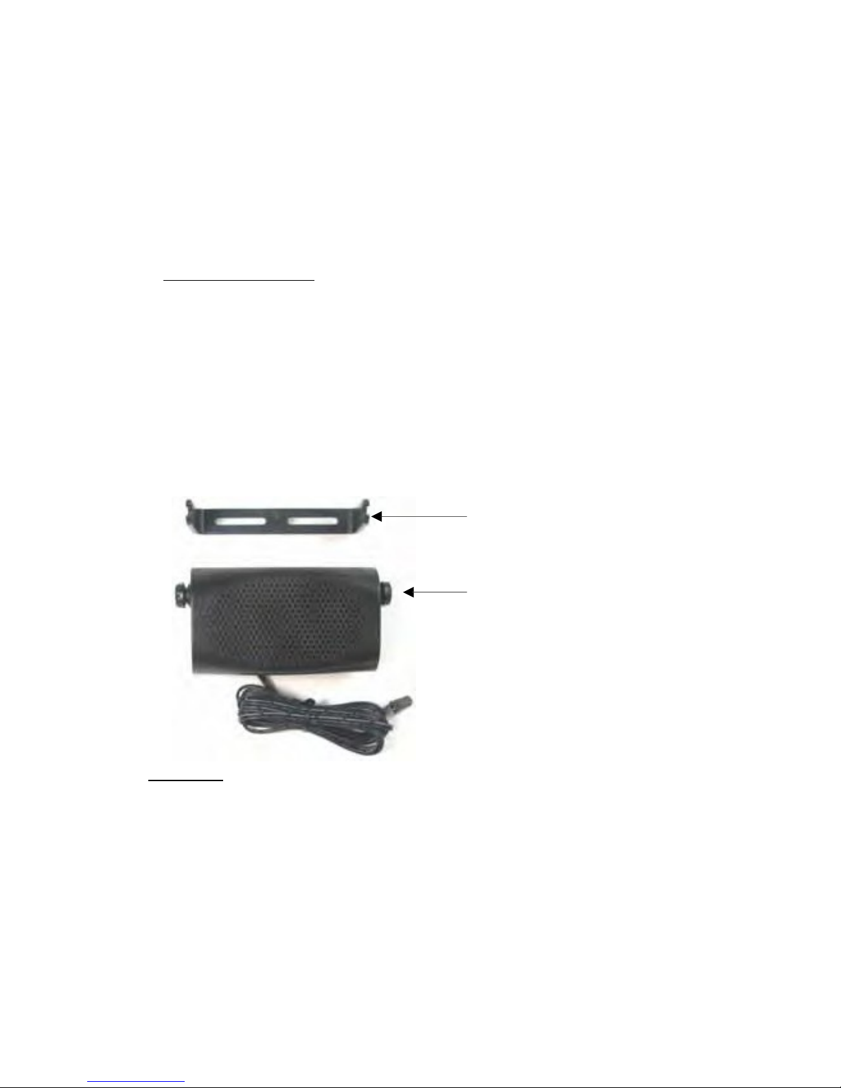
3.TheSpeakerincludesamountingbracket,permittingittobemounted
inavarietyofways.Loosenthethumbscrewsonthesideofthespeaker
andusingthemountingbracketasatemplate,drillthenecessary
mountingholesandsecurethebracketwiththeself‐tappingscrews
provided.
MountingBracket
ThumbScrews
Diagram 1
4.PositiontheSpeakeronthemountingbracketandsecureitby
tighteningthethumbscrews.Themountingbracketisusedto
permanentlymounttheSpeakerinplacewhilepermittingittobetilted
toadesiredangle.
5.Feedthecableoutofsighttothelocationwhereyouintendtomount
thejunctionbox.
6.Thespeakershouldbelocatedatleast3ft(1m)fromthevisor
microphone.Avoidplacingthespeakerwhereitfacesthevisor
microphone.
5
B.Microphone Installation
1.TheMicrophonesuppliedhasnoisecancellationfeaturesandassuch
theselectionofthecorrectpositionforthemicrophoneisvitalforthe
successfulperformanceoftheCarKit.
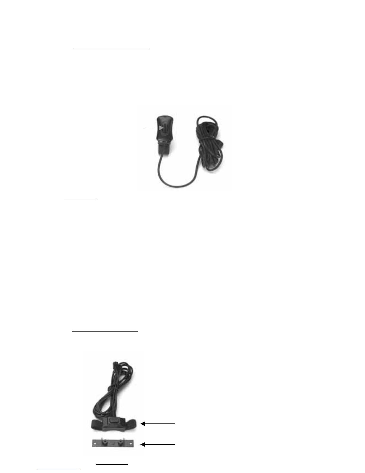
2.TheMicrophoneshouldbemountedeitheronthesunvisordirectly
aboveandfacingthedriver,orontheheadlinerjustaboveandfacingthe
driver.
Facingthedriver
Diagram 2
3.Thevisormicrophonehasanoisecancelingfeatureandmustbe
mountedfacingthedriverasshowninthepictureabove.
4.Toavoidvisualorphysicalobstruction,routethemicrophonecable
downinsidethedoormolding.Allowsufficientslackontheconnector
endofthecabletoreachtheJunctionBox.
5.Feedthecabletothelocationwhereyouintendtomountthejunction
box.
Note!Themicrophoneshouldnotbemountednearawindoworina
spotwhereroadandambientbackgroundnoisewouldbesubstantially
high(above85dBSPL).
C.Mounting of the PTT
1.ToattachthePTTtothegearlever,strapthePTTaroundthegearlever
usingtheVelcrostripattached,withthecordfacingdown.
Velcro Strip
Diagram 3
Flat Plastic
6
2.ToattachthePTTtoaflatsurface,removethe2screwsfromthe
bottomofthePTT,whichholdstheVelcrostripinplace.Removethe
stripsandreplacethesmallplasticpartthatheldthestripsinplacewith
thelargerflatplasticpartsuppliedwiththePTT.Screwthenewplastic
partinplace.
3.Feedthecableoutofsighttothelocationwhereyouintendtomount
thejunctionbox.
Caution:Makesurethereissufficientslackinthecabletoallowthefree
movementofthegearleverwithoutstretchingthePTTcable.
D.Installing the Power Cable
Caution!TheCarkitshouldbeusedwithanegativegroundelectrical
systemonly.Reversepolarity(positiveground)willtriggerprotection
circuitswhichcausethecablefusetoopen.Checkthegroundpolarity
beforeyoubegintheinstallationtopreventwastedtimeandeffort.12V
DCor24VDCautomotivesystemsaredirectlysupported.Determinethe
bestcableroutetothevehicleignitionforthePowerCablefromthe
locationwhereyouintendtomounttheJunctionBox.
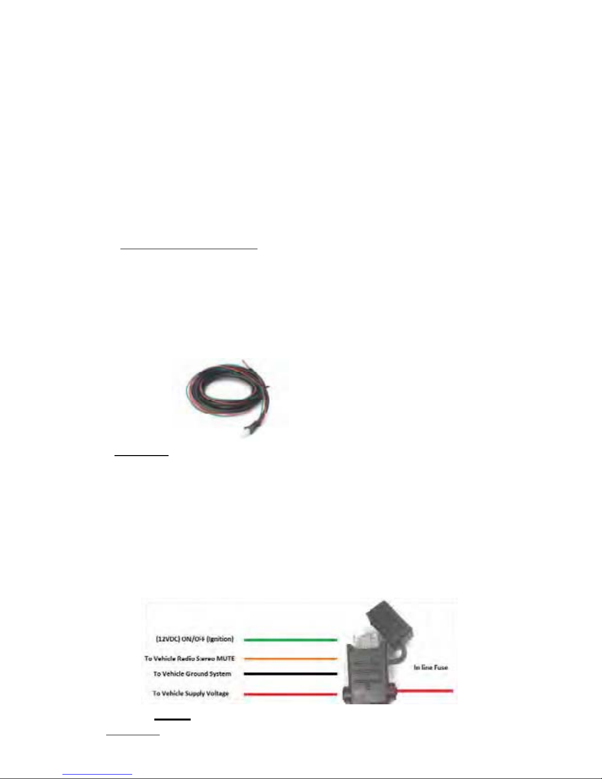
Diagram 4
1.Routetheblackleadofthemainpowercabletoaconvenientchassis
groundandtheredleadtothepositivesupplyvoltageconnectionpoint.
Ifitisnecessarytopenetratethefirewall,trytouseanexistingopening.
2.Ifthereisnoexistingopening,drillanewholeapproximately9/16”or
3.5cmindiameter.Makesurethatthereisclearanceontheoppositeside.
Insertagrommetintotheholetopreventdamagetothepowercable.
Whenmakingconnectionsontheenginesideofthefirewall,additional
in‐linefuseholder(included)shouldbeusedattheconnectionpoints.
GREEN MUST GO TO IGNITION OR CONNECTED WITH RED
Diagram 5

7
3.Cuttheblackleadtothedesiredlength.
4.Iftheconnectionisbeingmadeunderthedashorinthevehiclecabin,
connecttheblackleaddirectlytothechassisofthevehicle.
5.Iftheconnectionisbeingmadeintheenginecompartment,connect
thein‐linefuseholderbetweentheblackleadofthepowercableandthe
desiredchassisconnectionpoint.
Note!Donotconnecttheblackleadtothenegative(‐)batteryterminal.
TheCarKitcouldbedamagediftherewereamalfunctioninthevehicle’s
electricalsystem.
6.Cuttheredleadtothedesiredlength.Thisleadwillbeconnectedsuch
thatithaspositivesupplyvoltageatalltimes,evenwhenthevehicleis
turnedoff.
7.Iftheconnectionisbeingmadeunderthedashorinthevehiclecabin,
connecttheredleadtoapositivesupplyvoltagepoint.
8.Iftheconnectionisbeingmadeintheenginecompartmentordirectly
tothebattery,connectthein‐linefuseholderbetweentheredleadof
thepowercableandthedesiredpositivevoltageconnectionpoint.
9.Routeandconnectthegreenleadtoaconvenientignitionswitch
supplypointinthevehicle.If thegreen lead is not being connected to the
ignition, it MUST be connected together with the red lead.
Note!Anignitionswitchaccessoryterminalcanbeverifiedbymeasuring
theterminalwhileoperatingthevehicle’skeyswitch.Withtheignition
keyinthe“accessoryON”position,theterminalvoltageshouldmeasure
thevehicle’sbatteryvoltage.Withtheswitchinthe“OFF”position,it
shouldmeasurenearzero
Stereo Mute
Ifthevehicle’sstereosystemsupportsanexternalmutingfeature,route
andconnecttheorangewiretothecarstereosystem.Otherwise,the
orangewiremaybeleftunconnectedandcutoffortiedoutoftheway.
Note!TheCarKitsupportsan“EntertainmentMute”functionwhen
connectedtoacarstereosystemthatprovidesforexternalmuting.This
functioniscompatiblewithsystemsthatmutetheaudiooutputwhen
thecontrollineisconnectedtoground.
8
Connecting cables to Junction Box.
1.Locateapositionforthejunctionboxbeneaththedashboardonthe
passenger'ssideofthevehicleoronthecentersidepostbetweenthe
frontseats.
Itmustbeprotectedfromdirtandmoistureandmustbeafforded
adequatespaceforcooling.Theremustbesufficientspacetoallowfor
connectionofallcabling.
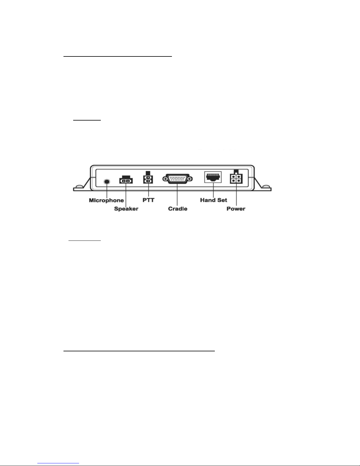
2.DO NOTmountthejunctionboxatthisstage. Firstconnectthe
Microphone, PTT, Speaker, Power cable and Cradle Cable to their
correspondingconnectionsontheJunctionBoxasindicatedinDiagram
below.
Diagram 6
3.Afterconnectingthepowercable'sconnectortotheJunctionBox,
cutinhalftheredwireattachedtothefusehousingsupplied.Cutthe
longredpowerleadtothedesiredlengthandconnect(crimp)ittothe
oneendofthewiretothefusehousing.
4.Connecttheotherendofthewirefromtheredfusehousingtothe
positive(+)sideoftheignition.Thefusehousingcanbesecuredinplace
byusingaplastictieorscrewthroughtheholeinthefuse'splastic
housing
5.Mountthejunctionboxinplaceusingthe2mountingscrewssupplied.
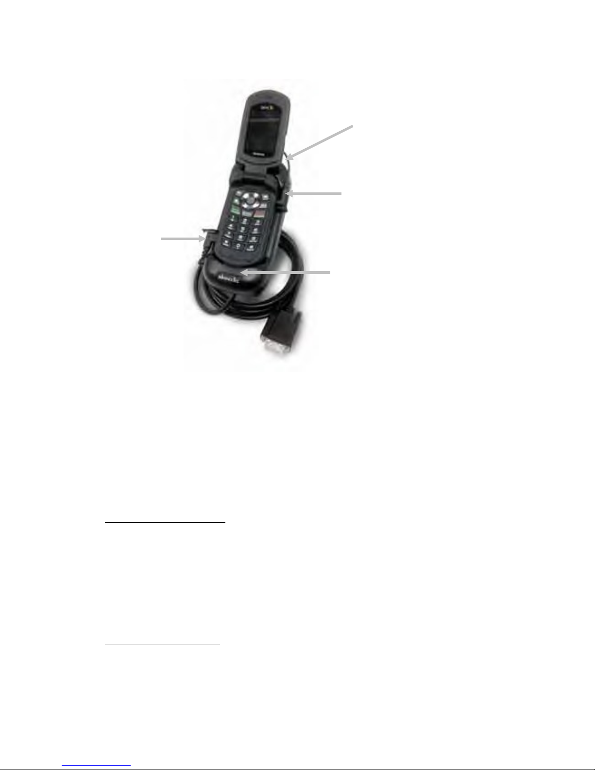
Inserting and removing the handset from cradle
1. Removetherubberprotectivecoverfromtheconnectorreceptacle
covering the micro USB connector on the left side of the handset
(handsetfacingyou)andalignthemicroUSBconnectorattheendonthe
onecablefromthebackofthecradleandinserttheconnectorintothe
handsetwiththecablefacingDOWN.
2.Removetherubberprotectivecoverfromtheconnectorreceptacle
coveringtheaudioconnectorontherightsideofthehandset(handset
facingyou)andalignthepinconnectorattheendoftheothercablefrom
thebackofthecradleandinserttheconnectorintothehandsetwiththe
cablefacingUP.
9
Pressbuttonon
topofcradleto
releasephone
InsertMicro
USB
connector
Insertside
audiocable
Insertportablebehind
ridgeonthecradle
Diagram 7
3.Insertthebottomofthehandsetbehindtheridgeonthecradleand
pressthetopofthehandsetbackintotheCradleasshowninDiagram7
aboveuntilitsnapsintoplace.
4.TurntheHandseton.
5.ToremovethehandsetfromtheCradle,pressthereleasebuttonon
thetopofthecradle.TheHandsetwillsnapforwardoutofthecradle.
Car Ignition connection
1.WhenthecarignitionisON,theCarKitwillstayonaslongasthe
cablesareinsertedintobothsidesonthehandset.
2.WhentheignitionisturnedOFFtheCarKitwillturnOFFafter60
minutes.
3.UseofthePTTinthevehiclewillturnontheCarKitfor8minutes,
afterwhichitwillturnoffagain.
Making adispatch call
1.Dialthedesirednumberonthehandset’skeypad
2.PressandholddownthePTTbutton.
3.Speaktowardsthevisormicrophone.
4.Adjustthespeakervolumeusingthehandset'svolumecontrol
5.Incomingaudiowillbeheardfromtheamplifiedspeaker.

10
Making or receiving ahands‐free telephone call
1.Toreceiveanincominghands‐freetelephonecall,presstheGreen
phonekey,onthehandset’skeypadorthePTTbuttonforashortperiod.
Aconfirmationtonethatthecallhasbeenansweredwillbeheard
throughthespeaker
NOTE!IfthePTTbuttonispressedformorethan2secondsitwillreject
andendthecall.
2.Tomakeahands‐freetelephonecall,placethehandsetintothecradle
anddialthedesirednumberonthehandset'skeypadandpressthe
phonekey.
3.Adjustthespeakervolumeusingthehandset'svolumecontrol.
4.Incomingaudiowillbeheardthroughthespeaker.
Note!Forbestaudioduringaninterconnectcallsetthevolumelevelat5
barsorless.
Call Waiting in both Hands‐free mode and with Privacy handset
1.Toansweranincomingcallduringanactivecall,pressthePTTbutton
forashortperiod.Thiswillputthecurrentcallonholdandanswerthe
incomingcall.
2.AshortpressonthePTTwilltogglebetweenthecalls.
3.PressingthePTTformorethan2secondswillterminatethecall.
Charging the battery
1.Withthehandsetturnedoff,thecarkitwillchargethebatteryto60%
inapproximately1hour.Thechargetimewillbelongerifthehandsetis
operationalduringchargetime.
2.Foroperatorconvenience,thehandset’sbacklightwillremainonfor
easeofviewingduringlow/no‐lightconditions.
NOTE! Batterieswillchargewithinthetemperaturewindowof‐10Cto
+40C(50Fto104F).Ifthebatteryisoutsidethetemperaturewindow,
nochargecurrentwillbesuppliedtothebattery.
Operating Specifications
Inputvoltagerange:11Vdcto32Vdc
Operatingambient:‐30Cto+60C
11
Optional Extras
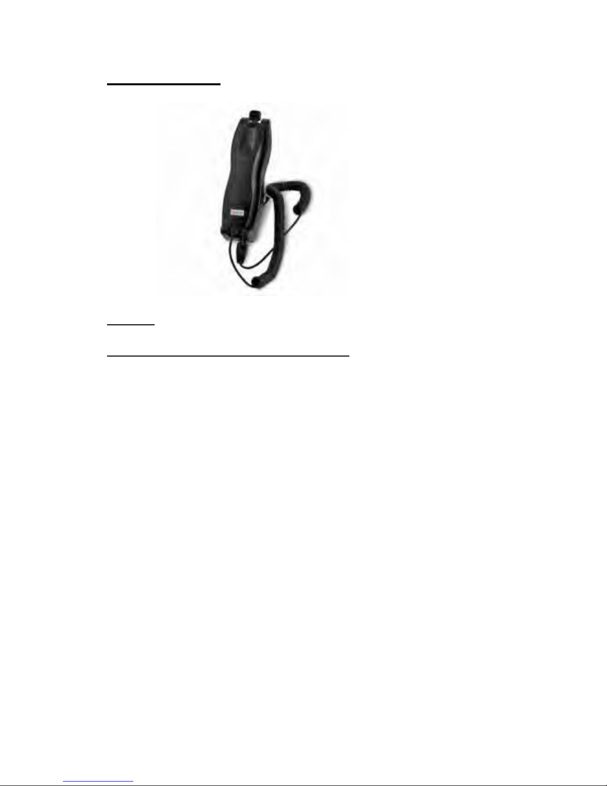
AT7107A–HandsetwithCradle
Part #AT7107A –Privacy Handset with Cradle
1.TousethePrivacyHandset,plugtheconnectorontheendofthecoil
cordintothecorrespondingRJ45receptacleontheJunctionBox.See
Diagram6above
2.Anactivecallcanbeterminatedandanincomingcallcanberejected
bypressingthePTTbuttononthebackofthePrivacyhandsetformore
than2seconds.
3.ToswitchfromanactivecallwiththePrivacyhandsettohands‐free
operation,placethePrivacyhandsetintoitscradle.Audiowillthenbe
routedtothespeaker. IfthePTTispressedformorethan2seconds,it
willterminatethecall.
4.IfthePrivacyhandsetisnotplacedintoitscradle,afterthecallis
terminated,aremindertonewillbeheardthroughthespeaker,one
minuteafterallactivityisfinisheduntilthePrivacyhandsetisreturnedto
itshandset.

12
AT8428A–PalmMic.
Part #AT8428A –Palm Mic
1.TouseaPalmMic.plugtheconnectorontheendofthecoilcordof
thePalmMic.intothecorrespondingRJ45receptacleonJunctionBox.
SeeDiagram6above.
2.Onceconnected,thepressingoftheswitchonthePalmMic.will
deactivatetheVisorMic.andactivatethePalmMic.
1150NW163rdDrive,Miami,FL33169
T: 305-623-3939 F: 305-623-3996
www.advancetec.com
www.advanceMobileGPS.com
Table of contents
Other AdvanceTec Automobile Accessories manuals


Popular Automobile Accessories manuals by other brands

Connects2
Connects2 CT51-MC03 quick start guide

Kolpin Outdoors
Kolpin Outdoors 20049 Product instructions

Prime Design
Prime Design UVX 201 Assembly instructions

Thule
Thule RideOn 950 instructions

Code 3
Code 3 SuperVisor Installation & operation manual

Connects2
Connects2 Connects2Vision CAM-PO1 user manual

Regency
Regency Digital-Display 2024 owner's manual

National Cycle
National Cycle Quantum N30213 Assembly instructions and owner's manual

Kompernass
Kompernass KH 4061 operating instructions

Body Armor 4x4
Body Armor 4x4 5145 installation instructions

Whispbar
Whispbar K161W Fitting instructions

FALCON RIDGE
FALCON RIDGE CF Moto U-Force 1000 Instructions for Installation and Care


