AdvanceTec AT6549A User manual

User Manual
Pro Install
Hands-Free Car Kit for
Kyocera™ DuraPlus™
Car Kit Part # AT6549A consists of:
1. Part # AT8231A Speaker
2. Part # AT8257A Junction Box
3. Part # AT8230A Visor Microphone.
4. Part # AT8232A Power cable
5. Part # AT9299B PTT
6. Part # AT8434A Ribbed Replacement Contact plate
Car Kit AT6549A requires one of the following two cradles to operate:
1. AT6698A Hands-free cradle WITHOUT Lock
2. AT6699A Hands-free cradle WITH lock
Optional Extras
1. Part #AT7107A Privacy Handset with cradle
2. Part # AT8428A Palm Mic.

2
Index
Page Details
1…………………………PartNumber
3………………………...ImportantPHONESettings
3…………………………ChangingPhoneContactPlate
4…………………………Warnings
4–5……………………SpeakerInstallation
5–6……………………MicrophoneInstallation
5–7……………………MountingPTT
7–8……………………PowerCableInstallation
8…………………………StereoMute
9…………………………ConnectingCablestoJunctionBox
10………………………Insertingandremovingphonefrom
cradle
10……………………….CarIgnitionconnection
10……………………….MakingDispatchCall
10–11………………..Making/ReceivingHands‐freecall
11……………………….CallWaiting
11……………………….ChargingBattery
11……………………….OperatingSpecifications
OptionalExtras
11–12………………..PhonewithCradle
12………………………..PalmMicrophone

3
PHONESETTINGS
Thefollowingphonesettingsareneededforoperationwiththe
AdvanceTechandsfree.TheHands‐freecarkitWILLNOTfunction
correctlywithoutthesesettings:
1. Press>Settings>DCSettings>DirectConnectON
2. Press>Settings>DCSettings>HeadsetMode>Headsetbutton
startsDCcalls.[DCbutton].
3. Press>Settings>Others>Accessibility>TTY>TTYOff.
4. IncreaseorDecreasethehandsfreevolumemustbedonewhile
phoneisconnectedtothehandsfreeandisonanactivecall.
!NOTE:
Toenablethephonetolatchintothecradleitisnecessarytoremoveand
replacethecontactplateonthebackofthephoneasfollows:
Diagram1
1.Removethe2screwsfromthePhoneContactPlateonthebackofthe
phoneandremovetheplatekeepingthescrewsastheywillbeneeded.
2.ReplacethePhoneContactPlatewiththeRidgedPlate(seebelow)
suppliedandscrewintoplaceintothebackofthephonewiththescrews
removedfromthePhoneContactPlate.
Diagram2
PhoneContactPlate
Ridgedplate
P/NAT8434A

4
Hands‐freeInstallation
Beforebeginningtheinstallationprocess,determinethebestlocationsfor
themountingoftheMountingBracket,Hand‐freeCradle,Push‐To‐Talk
(PTT)button,VisorMicrophone,SpeakerandJunctionBox.
Considerthefollowingguidelineswhenplanningtheinstallation:
DOuseallmountinghardwareprovided.
DOensurethatcablesarenotplacedunderstress.
DOfollowproper+and‐connections.
DOcrimpconnectorssecurely.
DONOTattachcomponentstoanypartofthevehiclethatisnot
rigidorissubjecttoexcessivevibration.
DONOTinstallcomponentsinareaswhererainorsnowcaneasily
getintothem,suchasnexttoavehiclewindow,whichmaybeleft
open.
DONOTdresscablesoversharpedgesthatcouldcausewearor
tearingofcableinsulation.
DONOTinstallcomponentsinlocationswheretheymight
interferewiththevehicleoperatororoperatingcontrols.
DONOTinstalltheHands‐freeCradlewhereitwillbedifficultfor
theoperatortoreach.
!WARNING
VEHICLESEQUIPPEDWITHAIRBAGS
Anairbaginflateswithgreatforce.DONOTplaceobjects,including
communicationsequipment,intheareaovertheairbagorintheairbag
deploymentarea.Ifthecommunicationequipmentisimproperlyinstalled
andtheairbaginflates,thiscouldcauseseriousinjury.
Itisrecommendedthattheinstallationofthevehiclecommunication
equipmentbeperformedbyaprofessionalinstaller/techniciantrainedin
therequirementsforsuchinstallations.Anairbag'ssize,shapeand
deploymentareacanvarybyvehiclemake,model,andfrontcompartment
configuration(forexample,benchseatvs.bucketseats).Contactthe
vehiclemanufacturer'scorporateheadquarters,ifnecessary,forspecificair
baginformationforthevehiclemake,model,andfrontcompartment
configurationinvolvedinyourcommunicationequipmentinstallation.
A.SpeakerInstallation
1.MounttheSpeakerbeneaththedashboard,onthepassenger'ssideof
thevehicle,outofthewayofthepassenger.DonotmounttheSpeaker
onthedashboardortherearwindowshelf.

5
2.TheSpeakershouldbelocatedmorethanfourfeetfromthejunction
box.
3.TheSpeakerincludesamountingbracket,permittingittobemounted
inavarietyofways.Loosenthethumbscrewsonthesideofthespeaker
andusingthemountingbracketasatemplate,drillthenecessary
mountingholesandsecurethebracketwiththeself‐tappingscrews
provided.
Diagram3
4.PositiontheSpeakeronthemountingbracketandsecureitby
tighteningthethumbscrews.Themountingbracketisusedto
permanentlymounttheSpeakerinplacewhilepermittingittobetilted
toadesiredangle.
5.Feedthecableoutofsighttothelocationwhereyouintendtomount
thejunctionbox.
6.Thespeakershouldbelocatedatleast3ft(1m)fromthevisor
microphone.Avoidplacingthespeakerwhereitfacesthevisor
microphone.
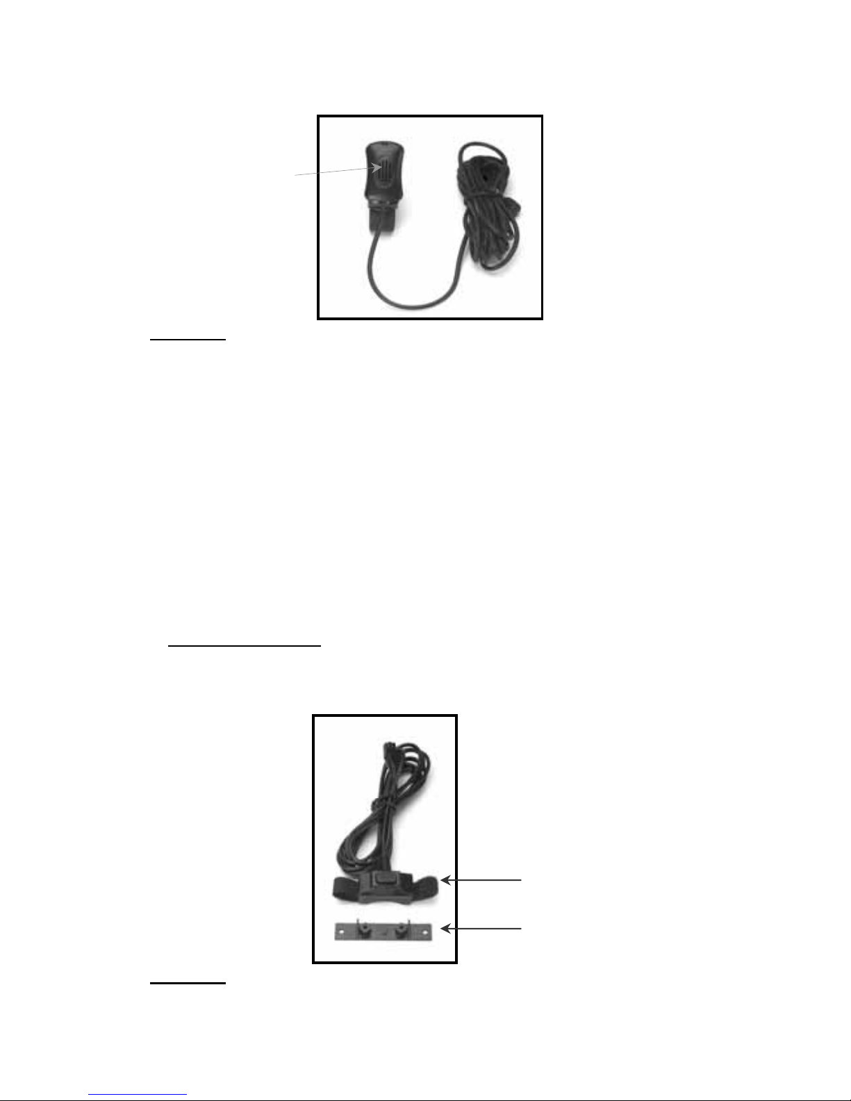
B.MicrophoneInstallation
1.TheMicrophonesuppliedhasnoisecancellationfeaturesandassuch
theselectionofthecorrectpositionforthemicrophoneisvitalforthe
successfulperformanceoftheCarKit.
2.TheMicrophoneshouldbemountedeitheronthesunvisordirectly
aboveandfacingthedriver,orontheheadlinerjustaboveandfacingthe
driver.
Mountin
g
Bracket
ThumbScrews
6
Diagram4
3.Thevisormicrophonehasanoisecancelingfeatureandmustbe
mountedfacingthedriverasshowninthepictureabove.
4.Toavoidvisualorphysicalobstruction,routethemicrophonecable
downinsidethedoormolding.Allowsufficientslackontheconnector
endofthecabletoreachtheJunctionBox.
5.Feedthecabletothelocationwhereyouintendtomountthejunction
box.
Note!Themicrophoneshouldnotbemountednearawindoworina
spotwhereroadandambientbackgroundnoisewouldbesubstantially
high(above85dBSPL).
C.MountingofthePTT
1.ToattachthePTTtothegearlever,strapthePTTaroundthegearlever
usingtheVelcrostripattached,withthecordfacingdown.
Diagram5
2.ToattachthePTTtoaflatsurface,removethe2screwsfromthe
bottomofthePTT,whichholdstheVelcrostripinplace.Removethe
Facin
g
thedriver
V
elcro Strip
Flat Plastic

7
stripsandreplacethesmallplasticpartthatheldthestripsinplacewith
thelargerflatplasticpartsuppliedwiththePTT.Screwthenewplastic
partinplace.
3.Feedthecableoutofsighttothelocationwhereyouintendtomount
thejunctionbox.
Caution!Makesurethereissufficientslackinthecabletoallowthefree
movementofthegearleverwithoutstretchingthePTTcable.
D.InstallingthePowerCable
Caution!TheCarkitshouldbeusedwithanegativegroundelectrical
systemonly.Reversepolarity(positiveground)willtriggerprotection
circuitswhichcausethecablefusetoopen.Checkthegroundpolarity
beforeyoubegintheinstallationtopreventwastedtimeandeffort.12V
DCor24VDCautomotivesystemsaredirectlysupported.Determinethe
bestcableroutetothevehicleignitionforthePowerCablefromthe
locationwhereyouintendtomounttheJunctionBox.
Diagram6
1.Routetheblackleadofthemainpowercabletoaconvenientchassis
groundandtheredleadtothepositivesupplyvoltageconnectionpoint.
Ifitisnecessarytopenetratethefirewall,trytouseanexistingopening.
2.Ifthereisnoexistingopening,drillanewholeapproximately9/16”or
3.5cmindiameter.Makesurethatthereisclearanceontheoppositeside.
Insertagrommetintotheholetopreventdamagetothepowercable.
Whenmakingconnectionsontheenginesideofthefirewall,additional
in‐linefuseholder(included)shouldbeusedattheconnectionpoints.
GREEN MUST GO TO IGNITION OR CONNECTED WITH RED
Diagram7

8
3.Cuttheblackleadtothedesiredlength.
4.Iftheconnectionisbeingmadeunderthedashorinthevehiclecabin,
connecttheblackleaddirectlytothechassisofthevehicle.
5.Iftheconnectionisbeingmadeintheenginecompartment,connect
thein‐linefuseholderbetweentheblackleadofthepowercableandthe
desiredchassisconnectionpoint.
Note!Donotconnecttheblackleadtothenegative(‐)batteryterminal.
TheCarKitcouldbedamagediftherewereamalfunctioninthevehicle’s
electricalsystem.
6.Cuttheredleadtothedesiredlength.Thisleadwillbeconnectedsuch
thatithaspositivesupplyvoltageatalltimes,evenwhenthevehicleis
turnedoff.
7.Iftheconnectionisbeingmadeunderthedashorinthevehiclecabin,
connecttheredleadtoapositivesupplyvoltagepoint.
8.Iftheconnectionisbeingmadeintheenginecompartmentordirectly
tothebattery,connectthein‐linefuseholderbetweentheredleadof
thepowercableandthedesiredpositivevoltageconnectionpoint.
9.Routeandconnectthegreenleadtoaconvenientignitionswitch
supplypointinthevehicle.Ifthegreenleadisnotbeingconnectedtothe
ignition,itMUSTbeconnectedtogetherwiththeredlead.
Note!Anignitionswitchaccessoryterminalcanbeverifiedbymeasuring
theterminalwhileoperatingthevehicle’skeyswitch.Withtheignition
keyinthe“accessoryON”position,theterminalvoltageshouldmeasure
thevehicle’sbatteryvoltage.Withtheswitchinthe“OFF”position,it
shouldmeasurenearzero
StereoMute
Ifthevehicle’sstereosystemsupportsanexternalmutingfeature,route
andconnecttheorangewiretothecarstereosystem.Otherwise,the
orangewiremaybeleftunconnectedandcutoffortiedoutoftheway.
Note!TheCarKitsupportsan“EntertainmentMute”functionwhen
connectedtoacarstereosystemthatprovidesforexternalmuting.This
functioniscompatiblewithsystemsthatmutetheaudiooutputwhen
thecontrollineisconnectedtoground.
9
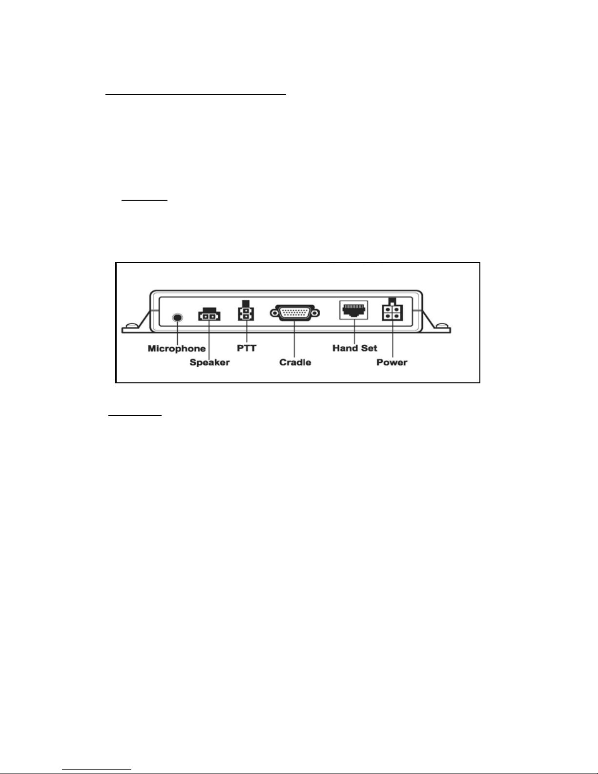
ConnectingcablestoJunctionBox.
1.Locateapositionforthejunctionboxbeneaththedashboardonthe
passenger'ssideofthevehicleoronthecentersidepostbetweenthe
frontseats.
Itmustbeprotectedfromdirtandmoistureandmustbeafforded
adequatespaceforcooling.Theremustbesufficientspacetoallowfor
connectionofallcabling.
2.DONOTmountthejunctionboxatthisstage.Firstconnectthe
Microphone,PTT,Speaker,PowercableandCradleCabletotheir
correspondingconnectionsontheJunctionBoxasindicatedinDiagram
below
Diagram8
3.Afterconnectingthepowercable'sconnectortotheJunctionBox,
cutinhalftheredwireattachedtothefusehousingsupplied.Cutthe
longredpowerleadtothedesiredlengthandconnect(crimp)ittothe
oneendofthewiretothefusehousing.
4.Connecttheotherendofthewirefromtheredfusehousingtothe
positive(+)sideoftheignition.Thefusehousingcanbesecuredinplace
byusingaplastictieorscrewthroughtheholeinthefuse'splastic
housing
5.Mountthejunctionboxinplaceusingthe2mountingscrewssupplied.

10
Insertingandremovingthephonefromcradle
Diagram9
1.Insertthebottomofthephonebehindtheridgeonthecradleand
pressthetopofthephonebackintotheCradleuntilitsnapsintoplace.
2.TurnthePhoneon.
3.ToremovethephonefromtheCradle,pressthereleasebuttonatthe
topofthecradle.Thephonewillsnapforwardoutofthecradle.
CarIgnitionconnection
1.WhenthecarignitionisON,theCarKitwillstayon.
2.WhentheignitionisturnedOFFtheCarKitwillturnOFFafter60
minutes.
3.UseofthePTTinthevehiclewillturnontheCarKitfor8minutes,
afterwhichitwillturnoffagain.
Makingadispatchcall
1.Dialthedesirednumberonthephone’skeypad
2.PressandholddownthePTTbutton.
3.Speaktowardsthevisormicrophone.
4.Adjustthespeakervolumeusingthephone'svolumecontrol
5.Incomingaudiowillbeheardfromtheamplifiedspeaker.
Makingorreceivingahands‐freetelephonecall
1.Toreceiveanincominghands‐freetelephonecall,presstheGreen
phonekey,onthephone’skeypadorthePTTbuttonforashortperiod.
Press buttonon
topofcradleto
releasephone
Insertphonebehind
ridgeonthecradle

11
Aconfirmationtonethatthecallhasbeenansweredwillbeheard
throughthespeaker
NOTE!IfthePTTbuttonispressedformorethan2secondsitwillreject
andendthecall.
2.Tomakeahands‐freetelephonecall,placethephoneintothecradle
anddialthedesirednumberonthephone'skeypadandpressthephone
key.
3.Adjustthespeakervolumeusingthephone'svolumecontrol.
4.Incomingaudiowillbeheardthroughthespeaker.
Note!Forbestaudioduringaninterconnectcallsetthevolumelevelat5
barsorless.
CallWaitinginbothHands‐freemodeandwithPrivacyphone
1.Toansweranincomingcallduringanactivecall,pressthePTTbutton
forashortperiod.Thiswillputthecurrentcallonholdandanswerthe
incomingcall.
2.AshortpressonthePTTwilltogglebetweenthecalls.
3.PressingthePTTformorethan2secondswillterminatethecall.
Chargingthebattery
1.Withthephoneturnedoff,thecarkitwillchargethebatteryto60%in
approximately1hour.Thechargetimewillbelongerifthephoneis
operationalduringchargetime.
2.Foroperatorconvenience,thephone’sbacklightwillremainonfor
easeofviewingduringlow/no‐lightconditions.
NOTE!Batterieswillchargewithinthetemperaturewindowof‐10Cto
+40C(50Fto104F).Ifthebatteryisoutsidethetemperaturewindow,
nochargecurrentwillbesuppliedtothebattery.
OperatingSpecifications
Inputvoltagerange:11Vdcto32Vdc
Operatingambient:‐30Cto+60C
OptionalExtras
Part#AT7107A–PrivacyHandsetwithCradle
1.TousethePrivacyHandsetwithcradle,plugtheconnectorattheend
ofthecoilcordintothecorrespondingRJ45receptacleontheJunction
Box.SeeDiagram8above

12
AT7107A–HandsetwithCradle
2.Anactivecallcanbeterminatedandanincomingcallcanberejected
bypressingthePTTbuttononthebackofthePrivacyHandsetformore
than2seconds.
3.ToswitchfromanactivecallwiththePrivacyHandsettohands‐free
operation,placethePrivacyHandsetintoitscradle.Audiowillthenbe
routedtothespeaker.IfthePTTispressedformorethan2seconds,it
willterminatethecall.
4.IfthePrivacyHandsetisnotplacedintoitscradle,afterthecallis
terminated,aremindertonewillbeheardthroughthespeaker,one
minuteafterallactivityisfinisheduntilthePrivacyHandsetisreturned
toitscradle.
AT8428A–PalmMicrophone
1.TouseaPalmMic.plugtheconnectorontheendofthecoilcordof
thePalmMic.intothecorrespondingRJ45receptacleonJunctionBox.
SeeDiagram8above.
2.Onceconnected,thepressingoftheswitchonthePalmMic.willde‐
activatetheVisorMic.andactivatethePalmMic.
AdvanceTec Industries, Inc
1150 NW 163rd Drive, Miami, FL 33169 T: 305-623-3939
www.advancetec.com
www.advanceMobileGPS.com
This manual suits for next models
6
Table of contents
Other AdvanceTec Automobile Accessories manuals


