AdvanceTec AdvanceMobile VX1 Instruction Manual

AdvanceMobile™
VX1
Part # AT3555A
Installation / User Manual
AdvanceTec Industries, Inc 1150 NW 163rd Drive, Miami, FL 33169
T: 305-623-3939 F: 305-623-3996 Toll Free: 1-800-881-8211
Company web site: www.advancetec.com
GPS services: www.advancemobilegps.com

2
Index
PageDescription
3Partnumbersandinstallationguides
3‐4InstallationWarnings
4 OperatingtheAdvanceMobileVX1
4SetuptheAdvanceMobileVX1
5InstallationofAdvanceMobileVX1
5InstallationofSpeaker
5‐6InstallationofMicrophone
6–7InstallationofPowerCable
8‐9InstallationofAntennaandGPSAntenna
9 InsertingofSIMcard
10ConnectingcablestoJunctionBox
11AdvanceMobileVX1ControlModule
12Programmingtelephonenumbers
12NavigatethroughtheChmmels
13AdjustingtheVolume
13Makingacall
14Answeringanincomingcall
14 TurningofftheAdvanceMobileVX1
14AdvanceMobileVX1LEDindicators
OptionalExtraAccessories
14 EmergencyPushButton
15PrivacyHandsetwithCradle
15PalmMic.
Specifications
16‐20 Specifications

3
TheAdvanceTecAdvanceMobile™VX1isdesignedtoprovidesecureand
convenientvehicularcommunicationontheGSMnetworkwithoptionalGPS
tracking.
TheAdvanceMobile™VX1consistsof:
1.Part#AT8254A JunctionBox
2.Part#AT8231A Speaker
3.Part#AT8230A VisorMicrophone(VisorMic.)
4.Part#AT8232APowercable
5.Part#AT8407AAntennaMagnetMount(Mag.Mount)
6.Part#AT3512AAdvanceMobile™VX1ControlModule
OptionalExtras
1.Part#AT8410APalmMicrophone
2.Part#AT7107APrivacyHandsetwithcradle
3.Part#AT9298AEmergencyPushButton.
4.Part#ATAT8408AGPSAntenna
!Note
AproperlyinstalledAdvanceMobile™VX1willminimizeservicecallsandequip‐
mentdowntime.Becauseofthewidevariationsinvehicledesign,these
instructionsshouldbemodifiedtosuiteachparticularinstallation.
Beforebeginningtheinstallationprocess,determinethelocationsforthe
mountingoftheVisorMicrophone,Speaker,JunctionBox,andMagneticMount
Antenna.
Considerthefollowingguidelineswhenplanningtheinstallation:
DOuseallmountinghardwareprovided.
DOensurethatcablesarenotplacedunderstress.
DOfollowproper+and‐connections.
DOcrimpconnectorssecurely.
DONOTattachcomponentstoanypartofthevehiclethatisnotrigidor
issubjecttoexcessivevibration.
DONOTinstallcomponentsinareaswhererainorsnowcaneasilyget
intothem,suchasnexttoavehiclewindow,whichmaybeleftopen.
DONOTdresscablesoversharpedgesthatcouldcausewearortearing
ofcableinsulation.
DONOTinstallcomponentsinlocationswheretheymightinterferewith
thevehicleoperatororoperatingcontrols.
DONOTinstallthePTTwhereitwillbedifficultfortheoperatortoreach.

4
VEHICLESEQUIPPEDWITHAIRBAGS
Anairbaginflateswithgreatforce.DONOTplaceobjects,including
communicationsequipment,intheareaovertheairbagorintheairbag
deploymentarea.Ifthecommunicationequipmentisimproperlyinstalledandthe
airbaginflates,thiscouldcauseseriousinjury.
Itisrecommendedthattheinstallationofthevehiclecommunicationequipment
beperformedbyaprofessionalinstaller/techniciantrainedintherequirements
forsuchinstallations.Anairbag'ssize,shapeanddeploymentareacanvaryby
vehiclemake,model,andfrontcompartmentconfiguration(forexample,bench
seatvs.bucketseats).Contactthevehiclemanufacturer'scorporateheadquarters,
ifnecessary,forspecificairbaginformationforthevehiclemake,model,and
frontcompartmentconfigurationinvolvedinyourcommunicationequipment
installation.
!WARNING
VEHICLESWITHANTI‐SKIDBRAKINGSYSTEMS
Forvehicleswithelectronicanti‐skidbrakingsystems,refertothe"Anti‐Skid
BrakingPrecautions,"Motorolapublication68P81109E34.Thispublicationcan
beorderedfromMotorola®WorldwideSystemsandAftermarketParts
Department.
OperatingtheAdvanceMobile™VX1
TheAdvanceMobile™VX1willallow:
1.Callstobemadetoupto10pre‐programmedphonenumbers.
2.CallstotheAdvanceMobile™VX1fromthepre‐programmedphonenumbers.
Acallfromaphonenumbernotprogrammedwillberejected.(Thisfeaturecan
beremovedbyAdvanceTecpriortoshipment.ConsultyourAdvanceTecsales
professional).
3.Acalltoanemergencyphonenumberwiththeoptional‐extraEmergency
PushButton(Seebelow)
SetupoftheAdvanceMobile™VX1
TheAdvanceMobile™VX1requiresanactivatedGSMSIMcard,togetherwitha
DATAplanifGPSserviceisrequired.TopurchaseanactivatedSIMcard,contact
yourlocalGSMnetworkprovidersalesrepresentativeorretailstore.
5
InstallationofAdvanceMobile™V1
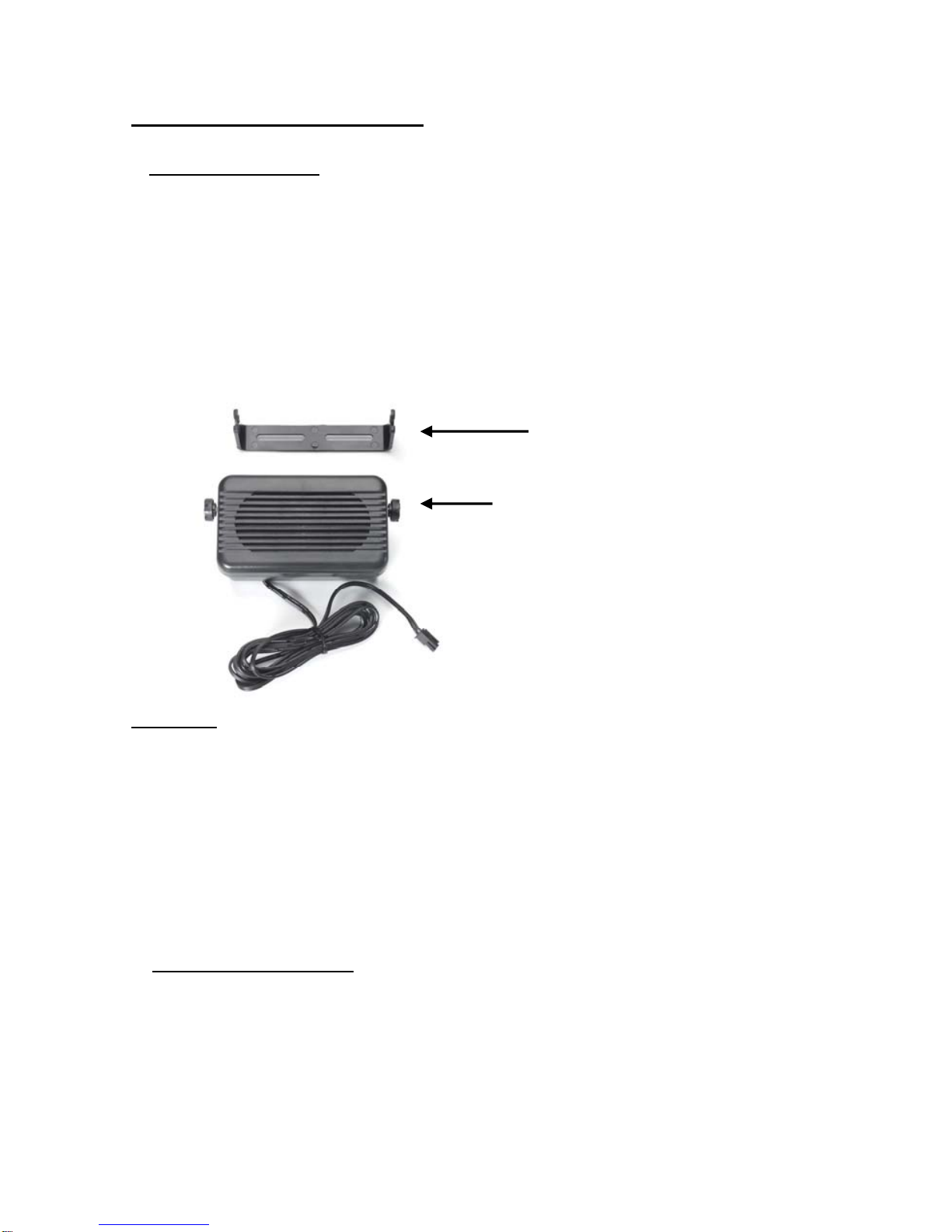
A.SpeakerInstallation
1.MounttheSpeakerbeneaththedashboard,onthepassenger'ssideofthe
vehicle,outofthewayofthepassenger.DonotmounttheSpeakeronthe
dashboardortherearwindowshelf.
2.TheSpeakershouldbelocatedmorethanfourfeetfromthejunctionbox.
3.TheSpeakerincludesamountingbracket,permittingittobemountedina
varietyofways.Loosenthethumbscrewsonthesideofthespeakerandusing
themountingbracketasatemplate,drillthenecessarymountingholesand
securethebracketwiththeself‐tappingscrewsprovided.
Mountin
g
Bracket
ThumbScrews
Diagram1
4.PositiontheSpeakeronthemountingbracketandsecureitbytighteningthe
thumbscrews.ThemountingbracketisusedtopermanentlymounttheSpeaker
inplacewhilepermittingittobetiltedtoadesiredangle.
5.Feedthecableoutofsighttothelocationwhereyouintendtomountthe
junctionbox.
6.Thespeakershouldbelocatedatleast3ft(1m)fromthevisormic.Avoid
placingthespeakerwhereitfacesthevisormicrophone.
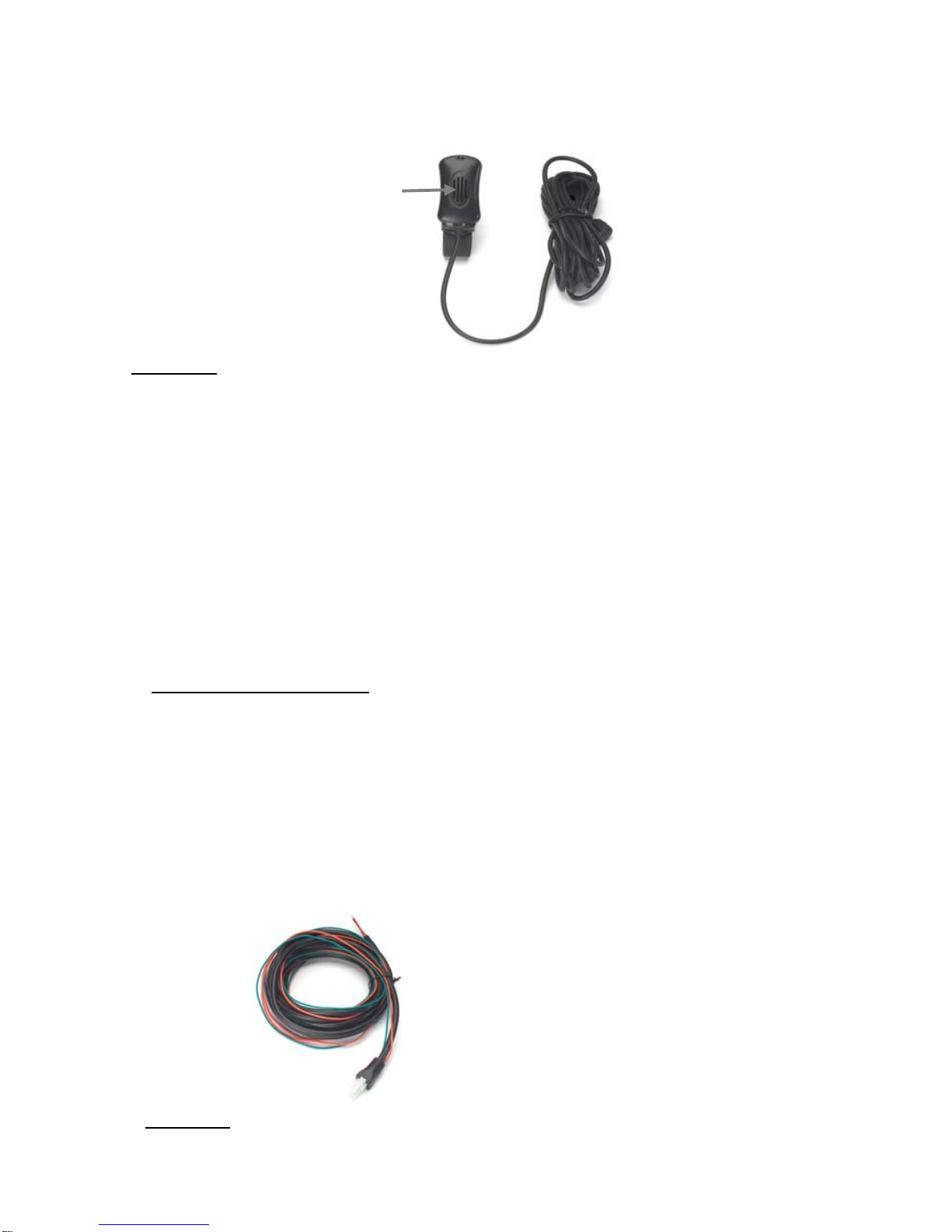
B.MicrophoneInstallation
1.TheMicrophonesuppliedhasnoisecancellationfeaturesandassuchthe
selectionofthecorrectpositionforthemicrophoneisvitalforthesuccessful
performanceoftheAdvanceMobile™V1
2.TheMicrophoneshouldbemountedeitheronthesunvisordirectlyabove
andfacingthedriver,orontheheadlinerjustaboveandfacingthedriver.
6
Facin
g
thedriver
Diagram2
3.Thevisormicrophonehasanoisecancelingfeatureandmustbemounted
facingthedriverasshowninthepictureabove.
4.Toavoidvisualorphysicalobstruction,routethemicrophonecabledown
insidethedoormolding.Allowsufficientslackintheconnectorendofthecable
toreachtheJunctionBox.
5.Feedthecabletothelocationwhereyouintendtomountthejunctionbox.
Note:Themicrophoneshouldnotbemountednearawindoworinaspot
whereroadandambientbackgroundnoisewouldbesubstantiallyhigh(above
85dBSPL).
C.InstallingthePowerCable
Caution:TheAdvanceMobile™VX1shouldbeusedwithanegativeground
electricalsystemonly.Reversepolarity(positiveground)willtriggerprotection
circuitswhichcausethecablefusetoopen.Checkthegroundpolaritybefore
youbegintheinstallationtopreventwastedtimeandeffort.12VDCor24VDC
automotivesystemsaredirectlysupported
DeterminethebestcableroutetothevehicleignitionforthePowerCablefrom
thelocationwhereyouintendtomounttheJunctionBox.
Diagram3
7
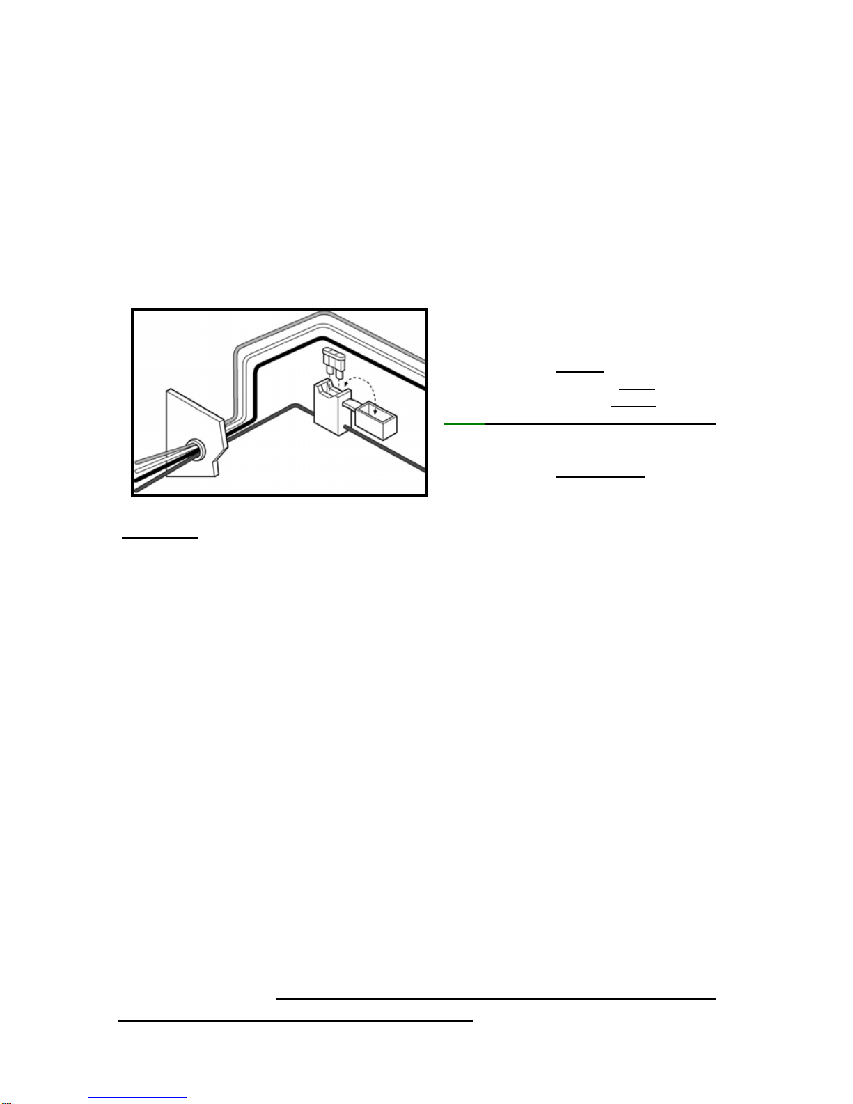
1.Routetheblackleadofthemainpowercabletoaconvenientchassisground
andtheredleadtothepositivesupplyvoltageconnectionpoints.Ifitis
necessarytopenetratethefirewall,trytouseanexistingopening.
2.Ifthereisnoexistingopening,drillanewholeapproximately9/16”or3.5cm
indiameter.Makesurethatthereisenoughclearanceontheoppositeside.
Insertagrommetintotheholetopreventdamagetothepowercable.When
makingconnectionsontheenginesideofthefirewall,additionalin‐linefuse
holder(included)shouldbeusedattheconnectionpoints.
←Green‐(12VDC)ON/OFF(Ignition)
←Orange‐ToVehicleStereoMUTE
←Black‐ToVehicleChassisGround
GREENMUSTGOTOIGNITIONOR
CONNECTEDWITHRED
←Red‐ToVehicleSupplyVoltage
Diagram4
3.Cuttheblackleadtothedesiredlength.
4.Iftheconnectionisbeingmadeunderthedashorinthevehiclecabin,
connecttheblackleaddirectlytothechassisofthevehicle.
5.Iftheconnectionisbeingmadeintheenginecompartment,connectthein‐
linefuseholderbetweentheblackleadofthepowercableandthedesired
chassisconnectionpoint.
Note!Donotconnecttheblackleadtothenegative(‐)batteryterminal.
TheAdvanceMobile™VX1couldbedamagediftherewereamalfunctioninthe
vehicle’selectricalsystem.
6.Cuttheredleadtothedesiredlength.Thisleadwillbeconnectedsuchthatit
haspositivesupplyvoltageatalltimes,evenwhenthevehicleisturnedoff.
7.Iftheconnectionisbeingmadeunderthedashorinthevehiclecabin,
connecttheredleadtoapositivesupplyvoltagepoint.
8.Iftheconnectionisbeingmadeintheenginecompartmentordirectlytothe
battery,connectthein‐linefuseholderbetweentheredleadofthepower
cableandthedesiredpositivevoltageconnectionpoint.
9.Routeandconnectthegreenleadtoaconvenientignitionswitchsupply
pointinthevehicle.Ifthegreenleadisnotbeingconnectedtotheignition,it
MUSTbeconnectedtogetherwiththeredlead.

8
Note!Anignitionswitchaccessoryterminalcanbeverifiedbymeasuringthe
terminalwhileoperatingthevehicle’skeyswitch.Withtheignitionkeyinthe
“accessoryON”position,theterminalvoltageshouldmeasurethevehicle’s
batteryvoltage.Withtheswitchinthe“OFF”position,itshouldmeasurenear
zero
StereoMute
Ifthevehicle’sstereosystemsupportsanexternalmutingfeature,routeand
connecttheorangewiretothecarstereosystem.Otherwise,theorangewire
maybeleftunconnectedandcutoffortiedoutoftheway.
Note!TheCarKitsupportsan“EntertainmentMute”functionwhenconnected
toacarstereosystemthatprovidesforexternalmuting.Thisfunctionis
compatiblewithsystemsthatmutetheaudiooutputwhenthecontrollineis
connectedtoground
D.MountingtheVehicularAntenna&GPSAntenna
1.Screwtheantennatotheexternalmagnetic(Mag)mountantennabase.Both
suppliedwiththeAdvanceMobile™VX1
2.MounttheMagMountantennaorotherexternalvehicularantenna(tobe
purchasedseparatelyifthesuppliedMagMountAntennadoesnotfityour
purposes).
NOTE!Forbestperformanceusealow‐losscoaxialcablewiththehighestgain
antenna.
3.Positiontheantenna,maintainingaseparationdistanceofatleast8inches
(20cms)betweentheantennaandthebodyofanyuserandnearbyperson,to
assurecompliancewiththeU.S.FCCregulationsonRFexposure.
GPSAntennaExternalAntenna
Diagram5
9
4Connecttheantennacabletotheexternalantennaconnectoronthejunction
box.SeeDiagram6below.
5.ForGPStracking,itwillbenecessarytopurchaseaGPSantenna,(available
fromAdvanceTecasanoptionalextra)andsubscribetotheAdvanceTec
proprietarywebbasedGPStrackingsoftware.Formoreinformationcontact
yourAdvanceTecsalesprofessional.
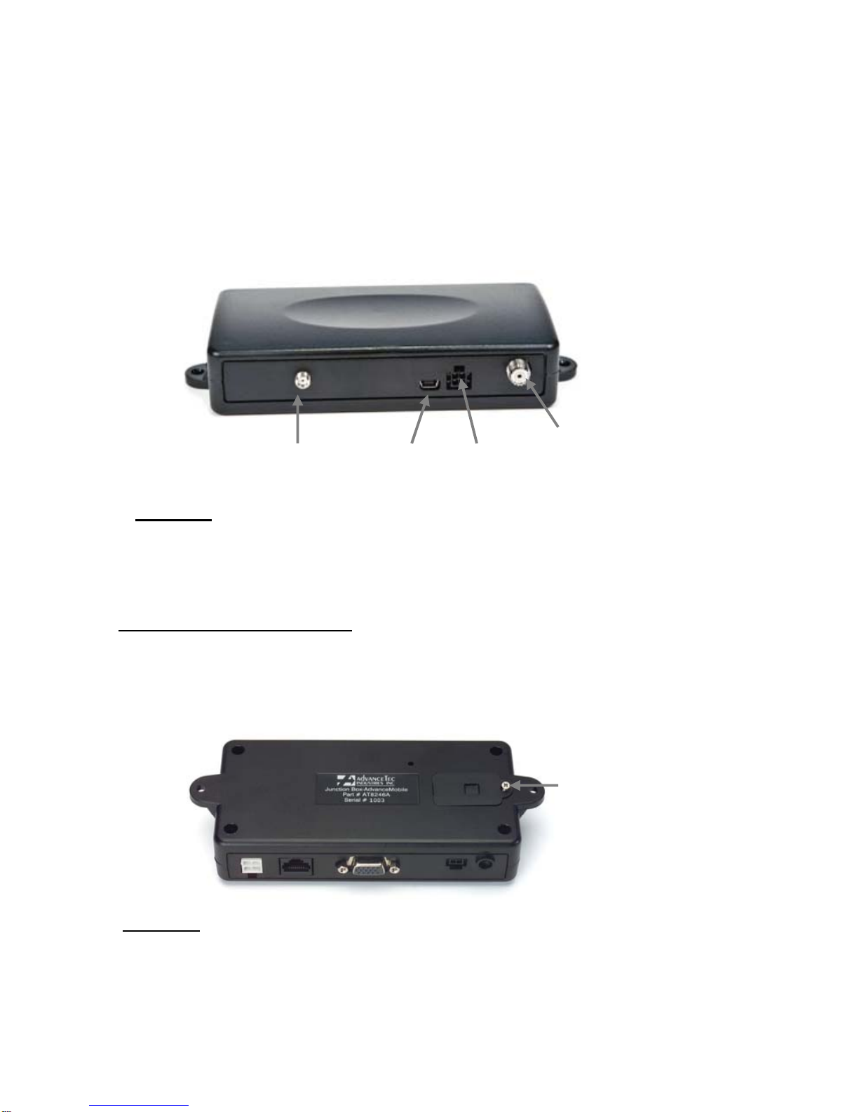
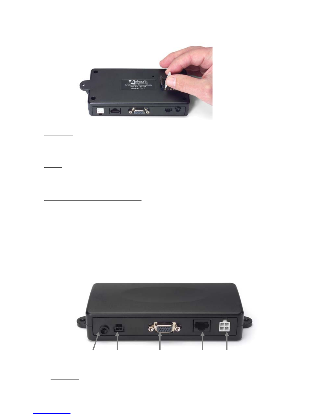
GPSUSBEmergencyExternal
AntennaDataOutputPushButtonAntennas
Diagram6
6.Feedtheantennacablesoutofsighttothelocationwhereyouintendto
mountthejunctionbox.
InsertingSIMintoJunctionBox
1.OpentheSIMdoorcoveronthebottomofthejunctionboxbyremovingthe
screwholdingitshut.
Screw
Diagram7
2.SlidethemetalSIMcovertotheleftandliftthecover.
3.InserttheSIMcardunderthemetalcoverandclosethemetalcoverandslide
totherighttolock.
10
Diagram8
4.ReplacetheSIMcoverandscrewitclosed.
NOTE:TheSIMcardcannotbeinsertedorremovedwhiletheJunctionBoxis
powered.ToremoveorreplacetheSIMcardafterinstallationhasbeen
completed,thepowercablemustbedisconnectedfromtheJunctionBox
ConnectingcablestoJunctionBox.
1.Locateapositionforthejunctionboxbeneaththedashboardonthepas‐
senger'ssideofthevehicleoronthecentersidepostbetweenthefrontseats.
Itmustbeprotectedfromdirtandmoistureandmustbeaffordedadequate
spaceforcooling.Theremustbesufficientspacetoallowforconnectionofall
cabling.
2.DONOTmountthejunctionboxatthisstage.ConnecttheMicrophone,
Speaker,PowercableandControlModuletotheircorrespondingconnections
ontheJunctionBoxasindicatedinDiagrambelow.
Mic.SpeakerControlModuleOptionalPower
PalmMic/.
Handsetw/Cradle
Diagram9
11
3.Connectthecoaxialantennacabletothecorrespondingconnectoronthe
oppositesideoftheJunctionBox.
4.Afterconnectingthepowercable'sconnectortotheJunctionBox,
cutinhalftheredwireattachedtothefusehousingsupplied.Cutthelongred
powerleadtothedesiredlengthandconnect(crimp)ittotheoneendofthe
wiretothefusehousing.
5.Connecttheotherendofthewirefromtheredfusehousingtothepositive
(+)sideoftheignition.Thefusehousingcanbesecuredinplacebyusinga
plastictieorscrewthroughtheholeinthefuse'splastichousing
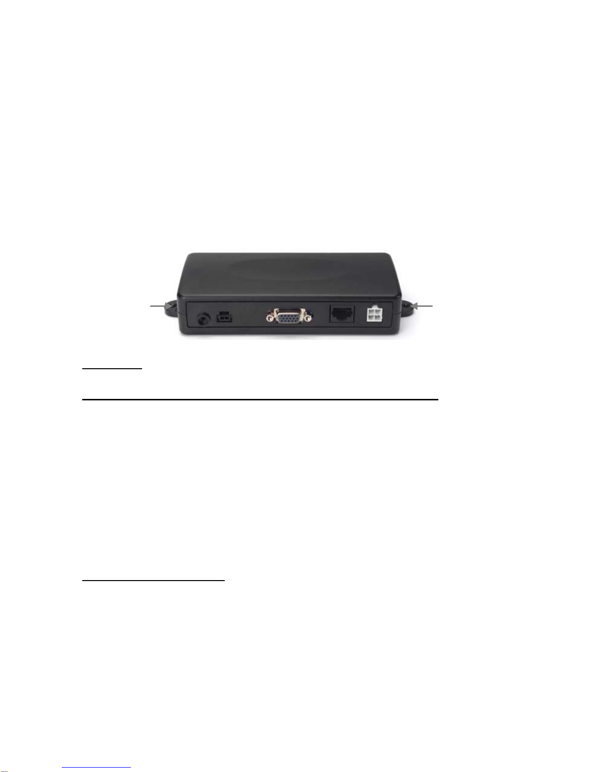
6.Mountthejunctionboxinplaceusingthe2mountingscrewssupplied.
Mounting
holes Mounting
holes
Diagram10
Registering the AdvanceMobile™ VX1 and Programming Numbers
1. Once the AdvanceMobile™ VX1 is powered and the activated SIM is
inserted, it will begin the registration process onto the GSM system. The
initial registration onto the GSM system can take up to 3 minutes.
2. Once the registration is successful, 5 short pulses will be heard through
the speaker.
3. After registration, the phone numbers with which the AdvanceMobile™
VX1 will communicate must be loaded. This can be done manually or with the
Utility software available from AdvanceTec, which will be loaded onto the
Control Module. See below.
Manually loading numbers
1. To manually load phone numbers into the AdvanceMobile™ VX1, initiate a
call to the AdvanceMobile™ VX1 from the phone with which you want the
AdvanceMobile™ VX1 to communicate.
2. Select a channel 0-9 on the Control Module
3. When the incoming call is heard on the AdvanceMobile™VX1 speaker,
press in the programming button next to the SIM flap by using a pen refill or
similar devise.

12
Diagram11
NOTE! The Programming button must be kept depressed until the
programming has been successfully made and the beeps heard on the
speaker.
3. Repeat this process until all the phone numbers with which the
AdvanceMobile™ VX1 will communicate have been loaded against the open
channel numbers of the Control Module.
AdvanceMobile™VX1ControlModule
MicroUSBConnector
LEDIndicator
Channel
Control
Buttons
Volume
Control
Buttons
SENDEND
Diagram12

13
TheAdvanceMobile™VX1ControlModuleisusedto:
A.ProgramthephonenumberswithwhichtheAdvanceMobile™VX1will
communicate(viatheUtilitySoftwareavailablefromAdvanceTec).
1ConnecttheUSBconnectoroftheUSB‐MicroUSBcablesupplied,toaUSB
slotofacomputer.
2ConnecttheMicroUSBconnectortotheMicroUSBreceptacleatthetopof
theControlModule.
3followtheprogramminginstructionssetoutintheUseGuideincludedwith
theUtilitySoftwareCDsuppliedseparatelywiththeAdvanceMobile™VX1
4Adifferentphonenumbercanbeprogrammedoneachofthe10channels
B.Navigatethroughthechannels.
1WiththeAdvanceMobile™VX1powered,presstheUPorDOWNChannel
ControlButtons.Channelnumbers0–9willshowintheControlModule
screen.
2Whenthedesiredchannelisreached,presstheGreenSENDbuttontoinitiate
thecall.
C.Adjustthevolume
1PresstheVolumeControlButtonsontheControlModuleUporDowntoraise
orlowerthevolumeoftheAdvanceMobile™VX1.
2Afteravolumebuttonispressed,ablinkingdotwillappearinthebottom
rightcornerofthescreentoindicatethatitisinthevolumemode.The
Minimumvolumeis0andtheMaximumis7.
3.Afterthevolumehasbeenadjusted,theblinkingdotwilldisappearto
indicatethattheunitisbackinthechannelmode.
TheChannelandVolumeselectedwillbesavedwhentheAdvanceMobile™VX1
ispoweredoff,provideditwaspoweredfor3minutesaftertheselectionwas
initiallymade.Theselectionsavedwillresumewhenitisnextpoweredup.If
theControlModuleloosescommunicationwiththemainunit,3horizontallines
willshowintheControlModulewindow.
Makingacall.
1.OntheControlModuleselectthechannelassociatedwiththephonenumber
youwanttocallandpresstheGreenSENDbutton.

14
2TheLEDwillturnorangeandtheringingwillbeheardonthe
AdvanceMobile™VX1speaker.
3Whenthecallisanswered,speaktowardsthevisormicrophone
4ToendthecallpresstheRedENDbutton.
Answeringanincomingcall
1.Toansweranincomingcall,presstheGreenSENDbutton.
3.Speaktowardsthevisormicrophone.
4.Toendthecellularcall,presstheREDENDbutton.
TurningOFFtheAdvanceMobile™VX1
1.WhenthecarignitionisON,theAdvanceMobile™VX1willstayon.
2.WhentheignitionisturnedOFFandthereisnoactivecallinprogress,the
AdvanceMobile™VX1willturnOFFafter30seconds.
3.TheAdvanceMobile™willremainonifanactivecallisinprogressevenifthe
ignitionisturnedOFF.
AdvanceMobile™VX1ControlModuleLEDindicators:
SteadyREDUnitnotregisteredwiththesystem
SteadyGREENUnitregisteredwiththesystem‐OK
OrangeCallinoperation
AlternatingGreen&Red
DatatransmittingforGPS.

15
OptionalExtraAccessories
1.EmergencyPushButton(EPB)
AnEmergencyPushButton(EPB)isavailableasanoptionalaccessoryfrom
AdvanceTec.
1.TheEPBwilladdanadditionalnumberontotheAdvanceMobile™VX1.This
emergencynumbercanbePolice/Fireoranyothernumberthatyoumaywish
tostore.
2.OncetheEPBispressed,itwillimmediatelydialthenumberstored,
irrespectiveofchannelthatisshowingontheControlModulescreen.
3.ToattachtheEPBtothegearlever,straptheButtonaroundthegearlever
usingtheVelcrostripattached,withthecordfacingdown.
V
elcro Strip
Flat Plastic
Diagram13
4.ToattachtheEPBtoaflatsurface,removethe2screwsfromthebottomof
thebutton,whichholdstheVelcrostripinplace.Removethestripsandreplace
thesmallplasticpartthatheldthestripsinplacewiththelargerflatplasticpart
supplied.Screwthenewplasticpartinplace.
5.Feedthecableoutofsightandpluginthe4pinconnectorontheback
junctionbox.SeeDiagram6above
Caution:Makesurethereissufficientslackinthecabletoallowthefree
movementofthegearleverwithoutstretchingthePushButtoncable.

16
PrivacyHandset(Part#AT7107A)
Diagram14
1.Toansweranincomingcall,liftthehandsetoutofthecradleanduseasyou
wouldaregularphonehandset.
2.Toterminatethecall,replacethehandsetintothecradle.
3.Totransferthecallfromthehandsettohands‐freemode,pressandhold
downtheroundbuttononthebackofthehandsetandreplacethehandsetinto
thecradle.Audiowillbetransferredtothespeaker
4.Ifthehandsetidnotplacedinthecradleandthereisnocallinprogress,a
beepeverysecondwillbeheardthroughthespeaker.
PalmMic(Part#AT8410A)
Diagram15
1.TouseaPalmMic.withtheAdvanceMobile™VX1,plugtheconnectoronthe
endofthecoilcordofthePalmMic.intothecorrespondingRJ45receptacleon
JunctionBox.SeeDiagram9above.

17
2. Press the button on the side of the Palm Mic to answer an incoming call.
Afterthecallisanswered,theconversationcanbecontinuedeitheronthe
PalmMicorontheVisorMic.
3.Toterminatethecall,presstheredENDbuttonontheControlModule.
Specifications
Input/Output
Inputvoltage10.5Vdcto32Vdc
Ignitiondetection:
Ignition“ON”2.5Vdcto32Vdc
Ignition“OFF”0Vto2.5VorOPEN
OutputsEntertainmentMute
OpenDrain
Continuouscurrentcapacity:50Ma
AudioSpecifications
RJ45Supports,PalmMIC#AT8410AandPrivacyHandsetPart#
AT7107A
2.5mmStereoaudiojack
Speakerimpedance:4Ohms10W
Microphone:EcoCancelingNoiseCanceling(UseonlyAdvanceTec
approvedVisorMic.part#AT8230A)
CommunicationSpecifications
FullDuplexCommunication
AutomaticStartup
AntennaImpedance:50Ohms
SIMcard:3Volts
SIMcarsPIN:Programmedbyuseronetime,automaticallyintroduced
Onward.PINsavedonNon‐Volatilememory
ReceiverSpecifications
FrequencyRange851min870MHzMaxinthe800MHzband
FrequencyRange935min941MHzmaxinthe900MHzband
ChannelSpacing25N/AKHz
Sensitivity(10%BER)–111dBmmax
StrongSignalBER0.1%maxRFlevel=‐80dBm
OverloadImmunity10%maxonchannel=_20dBm
IntermodulationImmunity‐45dBmminFar‐outinterferers
(Oncannel=‐108dBm)
AdjacentChannelImmunity‐51dBmmin

18
SpuriousResponseImmunity‐51dBmmin
Stability,unlocked5ppmmax
Stability,unlocked1.9ppmmax
SpuriousEmissionsperFCCrequirements(3m)
Conducted‐57dBm
Radiated500uV/m
TransientResponse0.01%BERduringRX‐TXRX
FrequencyAcquisition0.01%max±220HzRFinput
BlockingImmunity10%max
TransmitterSpecifications
FrequencyRangemin806max825MHzband
FrequencyRangemin896max900MHzband
Channelspacing25KHz
Power0.44Wmin0.7Wmax.Pulseaveragepower:basic
Terminalclass
TXBER0.7%max
ACCPR@25KHz60dBmin
FrequentStability5ppmmaxUnblockedtobase
SpuriousEmissions–13dBmmaxperFCCandIPU‐Rrequirements
GPSSpecifications
GPSModule
Sensitivity:‐152dBmTracking,‐142dBmAcquisition
Protocol:TAIP(ASCII)
Frequency:L1type(1575.42MHz)C/Acode
Channels:12channelsimultaneousoperation
Updaterate:1Hz
Accuracy
Horizontal:<3meters(50%).<8meters(90%)
Altitude:<16meters(50%),<16meters(90%)
Velocity:0.06m/sec.
PPS”+/‐50nanoseconds
Acquisition
Reacquisition:2sec.
HotStart9sec.
WarmStart35sec.
ColdStart(TTFF):39sec.Outofthebox:41sec

19
GPSAntennaConnection
SMA(SubMiniatureA)connectionwithamalecentercontact.Usethis
contactfortheGPSAntennaprovidedwiththeunit.
50Ohmsimpedance
GPSAntennaSpec.
Patch
CenterFrequency1575.42±1.023MHz(whencoveredwitharadome
andmeasuredbyLNAgroundplane)
Bandwidth(10dBreturnloss)10MHzmin
GainatZenith1dBtype
Gainay10°elevation‐5dBictype
PolarizationR.H.C.P.
AxialRatio5.0dBtype
Filter/LNA
CenterFrequency1575.42±1.023MHz
Gain30~37dB(pc:3V/32dB)
NoiseFigure1.4dBtype(ps:3V/1.35dB)
Fileroutbandattenuation
Dielectricfilter
7dBminfo±20MHz
20dBminfo±50MHz
30dBMinfo±100MHz
(fo=1575.42MHz)
OutputV.S.W.R2.0max
VoltageDC=2.5~5.5V
CurrentDC=8~23mA(ps:3V/10mA)
Antennaconnector
MiniUSBconnectorwithafemalecentercontact(Usethis
connectorfortheAntennaprovidedwiththeunit.
50Ohmsimpedance
EnvironmentalSpecifications
OperationalTemperature‐20to+60°C
StorageTemperature‐40to+85°C
ShockMIL‐STD‐810EMETHOD516.4Proc.1,18shocks40Ghalf‐
sine6–9msec18

20
Shocks2500g’s,0.00075‐secondpulse
Vibration2X‐EIA(nottestedelectronicallyduringvibration)Sine
20–2000Hz,4Gpeak
1hrperaxis–3axis(X,y,z)Random20–2000Hz,6GRMS;1hr
peraxis–axis(x,y,z)
AdvanceMobile™ VX1
GPS services
www.advancemobilegps.com
AdvanceTec Industries, Inc 1150 NW 163rd Drive, Miami, FL 33169
Tel: 305-623-3939 Toll Free: 1-800-881-8211
www.advancetec.com
This manual suits for next models
1
Table of contents
Other AdvanceTec Automobile Accessories manuals


