Advantage Controls GF with MegaTron XS Operating instructions
1
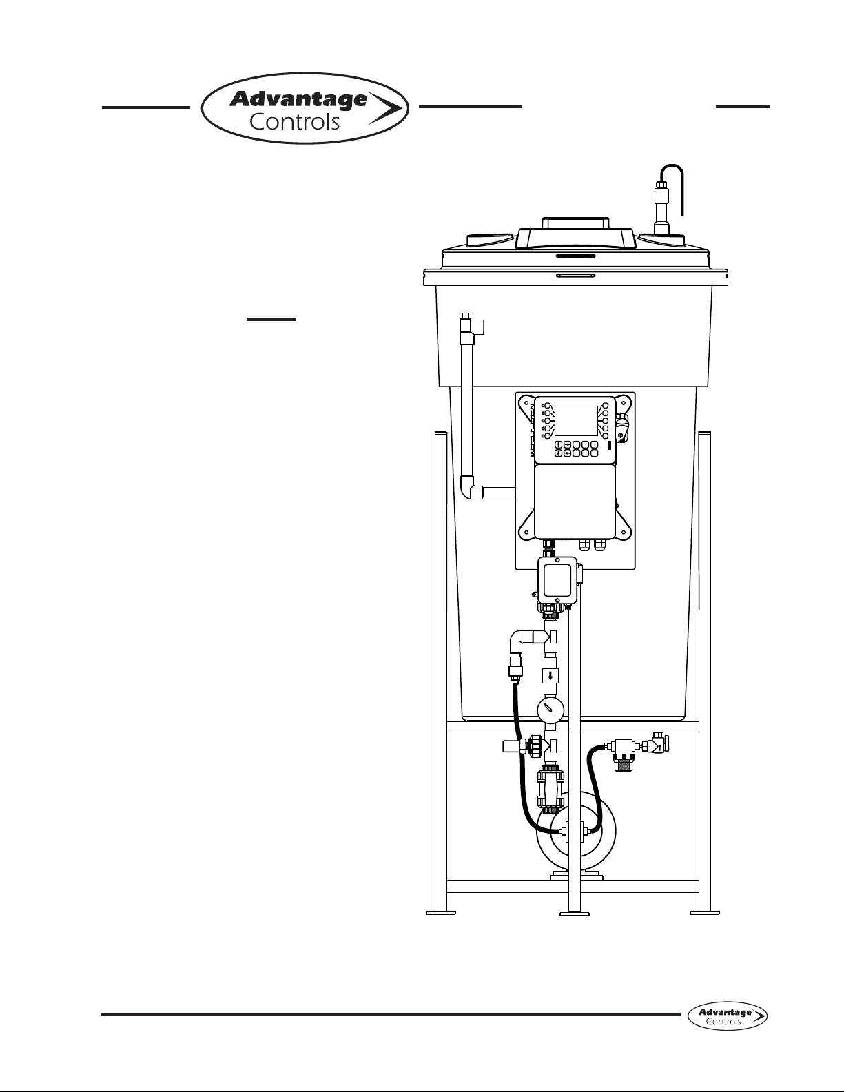
Manual
Model GF
Digital Glycol
Feeder with
MegaTron XS
Controller
Installation
Maintenance
Repair
Manual
Advantage Controls
P.O. Box 1472
Muskogee, OK 74402
Phone: 918-686-6211
Fax: 888-686-6212
www.advantagecontrols.com 11/2018
3
4
5
2
1
8
9
0
7
6
SET UP
RUN
CANCEL HELP BACK
ENTER HOME

2
Table of Contents
I. Introduction .................................................................................................2
............................................3
III. Installation...................................................................................................5
Electrical Wiring ...............................................................................5
Mounting Instructions.......................................................................5
Typical Installation and Measurements ............................................6
Start Up & Calibration Procedures...................................................7
IV. Front Panel Description ............................................................................10
V. System Operation Overview ..................................................................... 11
VI. Menu Navigation ....................................................................................... 11
VII. USB Functions ..........................................................................................20
VIII. Troubleshooting and Maintenance............................................................21
IX. Parts List ...................................................................................................23
X. Wiring Diagrams.......................................................................................25
XI. Warranty ...................................................................................................26
Reference Chart % Propylene Glycol.............................................................................27
Reference Chart % Ethylene Glycol...............................................................................27
I. Introduction
The Advantage Controls Glycol Feed Systems are design to regulate pressure in closed loop Hydronic
Heating and Cooling applications.
The Advantage Controls XS Series Glycol Feeders are our advanced design microprocessor based
controller with communication options previously unavailable with earlier models.
by ETL. With standard outputs of: (2) dry contact relays (one for alarms and our for pump on), (1) timer
for agitator control, 20 key data inlay, large multi-line display, audible alarm, motor starter / high amp
Advantage Controls Glycol Feeders are stand alone pre-wired, pre-plumbed systems designed for ease
of installation. Our systems are mounted on a powder coated steel frame with anchor points.
model number against the selection guide for better understanding of your system.
Please read this instruction manual to become familiar with your system.
3
II. ModelNumberingandGeneralSpecications
BUILD A MODEL GF - 1A1A1G- C1
TANK SELECTION
0 = No tank
1 = 55 gal (208L) poly
2 = 100 gal (378L) poly
3 = 30 gal (113L) poly
5 = 5 gal (18L) no stand, 30 gpd pump only
7 = 150 gallon poly (567L)
STAND SELECTION
A = Painted steel stand
B = Painted steel stand w/ mixer bracket
C = Tank top mount (no tank included)
D = Portable stand with built in rollers
E = No stand (for 5 gal tanks)
PUMP SELECTION
*Dual pump sys. require 2 pump selections (i.e., -11)
0 = No pump
5 = 30 gpd at 100 PSI; solenoid driven
PUMP CONFIGURATION
B = Alternating pumps for single loops
(requires 2 pump selections)
C = Pump plumbed for transfer duty into tank
LOOP SELECTION
*Dual loop sys. require 2 loop selections (i.e., -11)
0 = No loop
1 = Sch 80 PVC loop; 100 PSI max; 100°F max
2 = Copper loop; 100 PSI max; 180°F max
3 = Carbon steel loop; 100 PSI max
CONTROL SELECTION
existing single / dual pump system. Mounted to
replacement panel with (1) audible alarm and system
matching high amp / relay box(es)
prewired for a single pump system.
prewired for a dual pump system.
OPTIONS
1 = 240V
3 = Solenoid valve for pressure relief
5 = Position backcheck to use tank for expansion
C1 = Communications card Internet *
C11 = Communications card Modbus *
C12 = Communications card BacNet *
G = PUMP ON - dry contact relay
H = 1/4” PVC pipe instead of pump suction tubing
M = Mixer controls (order mixer separate)
O4= Four 4-20mA outputs *
* Options C1, C11, C12, O4 require control option D, G or H.
3
4
5
2
1
8
9
0
7
6
SETUP
RUN
CANCEL HELP BACK
ENTER HOME
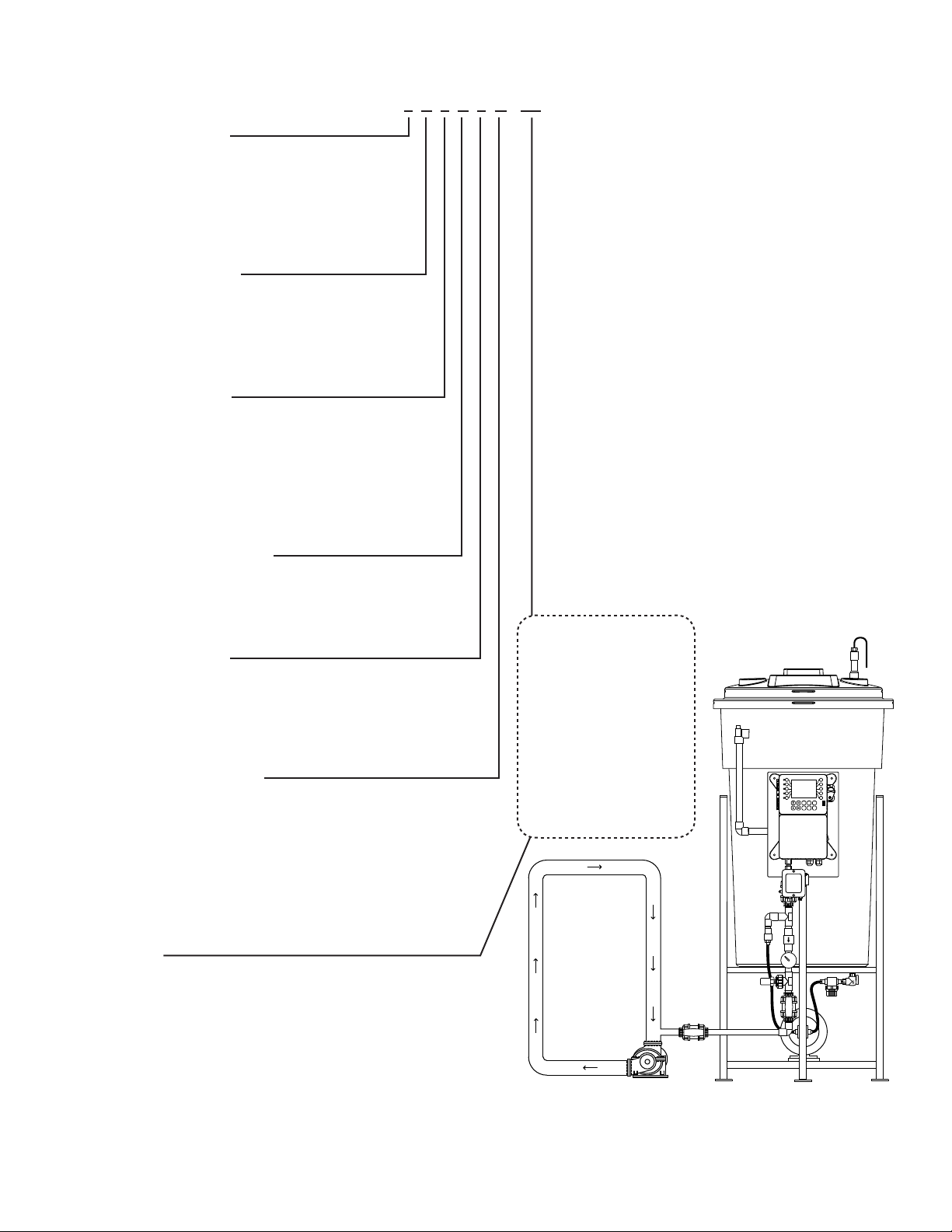
System
Connection
Circulation Pump
Specications
Electrical
• Input 120 VAC, 60 Hz
• Alarm Dry Contact
•
Plumbing
• Standard Schedule 80 PVC
• Optional Copper or Black Iron
Enclosure
Heavy Duty NEMA 4X style, high
impact thermoplastic with padlockable
gasketed Lexan viewing door
Pressure Gauge 0-100 psi (0-6.9 bar)
Dimensions
See measurements on page 6.
Shipping Weight
330 lbs (149.69 kg) approx.
Most units include
poly tank and stand,
low level switch with
audible alarm (100db),
motor starter / high
amp relay, dry contact
alarm, pressure relief
valve and plumbing
assembly with
pressure gauge and
sensor.

4
Base Functions
MegaTronXS units have several base system control functions and unit optional features. Your unit may
be supplied with one or more of the features described in this manual. To determine what features apply to
your unit check the model number label located on the controller enclosure.
Base System Control Functions
F1 - (1) Timer Standard
Whole Unit Optional Features
A- Conduit Connections
C1 - Communications card Internet
C11 - Communications card Modbus
C12 - Communications card BacNet
Model numbers start XS followed by the System Control functions. A dash separates the whole unit options
listed after all base system control functions. Example: XSCPF3E-N4.
Notice: Your unit may not have all features and functions described in this manual. This list represents our
most popular options, additional option codes are available.
Description of Unit
MegaTronXS controllers control a single recirculating water system including closed loop applications and
may have various features depending on the model number.
Standard Timer
The standard timer is designed to automate a mixer action activating a relay output. This timer can be
programmed to be one of the following types.
*1. Pulse Time - Accepts pulses from a make-up water meter (supplied separately). It can accumulate
1-9999 gallons before activating the timer to run.
*2. Feed with Bleed - Activates the relay output simultaneously with the bleed and limits the amount
of time the relay output will be on during the bleed cycle.
*3. Feed after Bleed
for the set percentage of that bleed cycle.
4. Recycle
cycle time.
5. 28 Day - The timer is based on a 28 day cycle with four independent programmable feed cycles
with prebleed and bleed lockout settings.
* Note: These functions are for application other than glycol feeders.

5
III. Installation
Electrical Wiring
The MegaTron XS series digital glycol feeder controller has an internal regulated power supply that will
operate in the range of approximately 90 to 250 VAC at 47 to 63 Hz on the incoming wiring. Output relay(s)
are protected with a replaceable fuse. Each relay’s output voltage will equal incoming line voltage. The
Standard prewired units are supplied with a 8 foot, 16 AWG, 3 wire grounded, 120 VAC USA power cord for
incoming power.
NOTE:Liquidtightttingsandlabeledsignalleadcablesareprovidedforallsignal(lowvoltage)
connections,lowdrumlevelandpressuretransducer.
WARNINGS:
1. The controller should be connected to its own isolated circuit breaker, and for best
results, the ground should be a true earth ground, not shared. Wiring must be done
according to all applicable local codes.
2. Power(linevoltage)mustbedisconnectedwhilemakinganyconnections.Ifpoweris
suppliedtotheunit,linevoltagewillbepresentontherelaycards.
3. Lowvoltagesignalwires(transducer,level,alarm,etc.)shouldneverberuninconduit
withhighvoltagewires.
Mounting Instructions
Select a mounting location that provides the operator easy access to the unit and a clear view of the controller.
The location should be convenient to grounded electrical connections and system plumbing connections.
Mount the glycol feeder stand to a level concrete pad using the ½” mounting holes in the base of the stand.
Concrete pad construction and anchoring bolts must comply with local building codes. The required sample
line plumbing should be connected to the return header of the Hydronic system
WARNING:
Avoid locations that expose the controller to direct sunlight, vapors, vibration,
liquid spills or extreme temperatures; less than 0°F (-17.8°C) or greater than 120°F (50°C).
EMI(electromagnetic interference) from radio transmissions and electric motors can also
causedamageorinterferenceandshouldbeavoided.
!
!

6
Typical Installation and Measurements
3
4
5
2
1
8
9
0
7
6
SETUP
RUN
CANCEL HELP BACK
ENTER HOME
System
Connection
Circulation Pump
B
A
E
Side View Shown
1/4” bolt hole drilled
3/4” from outside edge
Note: This is for mounting
holes only. Controller will
extend beyond this depth.
GLYCOL STAND FOOT PRINT
C
D
A B C D E
30gal
113.5L
23 ¾”
60.3 cm
51”
129.5 cm
27 ½”
69.8 cm
25 ½”
64.7 cm
30 ½”
77.4 cm
55gal
208.1L
27 ½”
69.8 cm
65”
165.1 cm
27 ½”
69.8 cm
25 ½”
64.7 cm
32”
81.2 cm
100gal
378.5L
31 ¼”
79.3 cm
66”
167.6 cm
37”
93.9 cm
35”
88.9 cm
38”
96.5 cm

7
Glycol Feeder Start-Up Procedure
Complete all installation steps before beginning this procedure. Ensure that all controlled devices (pumps,
solenoid valves, etc.) are operational and connected to the controller.
WARNINGS:
Before applying power to the controller, remove the fuse(s) from the fuse holder(s) located on the
high amp relay extension. There will be two (2) fuses on duel pump system. Reasoning behind
this is, factory settings may not agree with your system and this gives time for you to set your
parameters before applying power to the pump or pumps.
construction debris.
2. Check plumbing as it may have become loose from vibrations during shipping.
3. Fill Tank
4. Open the valve closest to the drain port of the plumbing assembly by turning the handle clockwise.
Water will pass through the sample stream assembly.
5. Ensure that the system pressure does not exceed 100 psi.
gauge agrees with system pressure. This value may vary do to connection to Hydronic systems
placement.
8. Once you are familiar with the controller from either reading the instruction manual or trial and error,
proceed with setting perimeters that are correct for your hydronic system.
extension.
10. Power ON the control to verify proper operation.
PressureReliefCongurationProcedure
1. Pressure relief values are set at 75 psi by default from the factory.
2. To increase the psi, spin the valve clockwise.
3. To decrease the psi, spin the valve counter clockwise.
4. Close drain port valve slowly to raise system pressure to the relief level.
5. Open drain port valve to relieve system pressure and conclude test.
Alarm Buzzer Disable and Enable Procedure
1. Press the 0 key at the home screen to enter into the relay status screen.
2. Press the 2 key twice after entering into the relay status screen to disable the alarm buzzer.
3. Press the 2 key once more to set the relay back to the normally pressure automated state.
4. Press the 2 key once more to force the alarm buzzer relay ON.
!
8
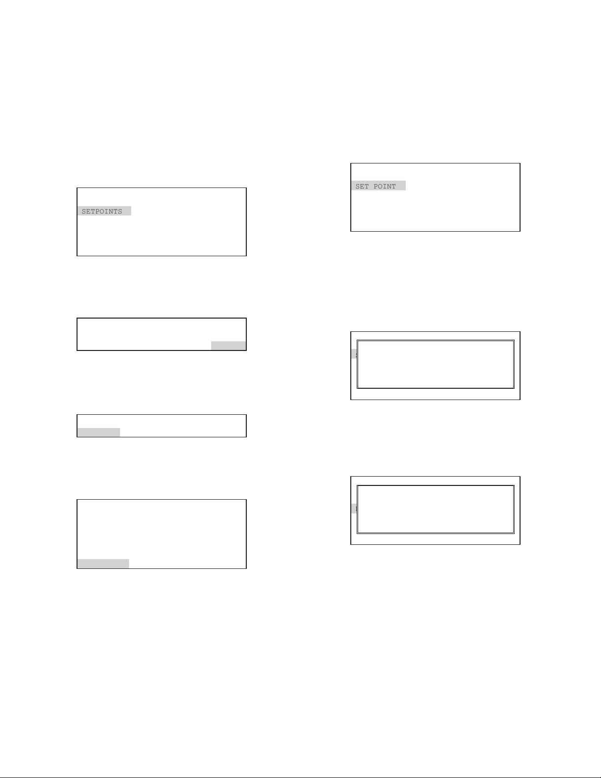
PressureSetpointCongurationProcedure
IftheseareimproperlysetbyenteringanA/Dvalue
for the settings while the input is not seeing the
correct signal a signal generator will be required to
reset the calibration.
Step 1:
Push the HOME button to leave Calibration and go back
to the HOME menu screen. From here push SETPOINTS
(Button 1) to go to the next screen
>HOME SETUP<
SETPOINTS DATE/TIME
CALIBRATION CONFIGURE
TIMERS HISTORY
CUSTOMIZE TOTALIZERS
ALARMS RELAYS
Step 2:
This is the Setpoints Setup Screen. From here push mA
IN (Button 7) to go to the next screen
>SETPOINTS SETUP<
SENSORS
mA IN
Step 3:
This is the mA Inputs Screen. From here push INPUT 1
(Button 1) to go to the next screen
>mA INPUTS<
INPUT 1
Step 4:
This is the mA Input 1 Setpoint Review Screen. From here
push SETPOINTS (Button 5) to go to the next screen
>mA INPUT 1 SETPOINT<
mAIN1
SET POINT: 500%
RISING CONTROL
DIFFERENTIAL: 20
HIGH ALARM AT: 1000(OFF )
LOW ALARM AT: 0(OFF )
LIMIT TIME: 00:01 HH:MM
SETPOINTS
Step5:
This is the mA Input 1 Setpoint Change Screen.
From here you can set SET POINT (Button 1),
DIFFERENTIAL (Button 2), HIGH ALARM
(Button 3), LOW ALARM (Button 4) and LIMIT
TIME (Button 5). Press the desired button to go
to the next screen
>mA INPUT 1 SETPOINT CHANGE<
SET POINT
DIFFERENTIAL
HIGH ALARM
LOW ALARM
LIMIT TIME
Step 6:
Set the value of SET POINT by using the number
keys. Use the left arrow to set the reaction
direction of the set point between RISING or
FALLING.Then press ENTER
to the previous screen
>mA INPUT 1 SETPOINT CHANGE<
SET POINT
DIFFERENTIAL
HIGH ALARM
LOW ALARM
LIMIT TIME
SET POINT (RISES TO 00500 %)
[RISES][__ ] %
USE NUMBER KEYS TO CHANGE, PRESS
ENTER TO ACCEPT OR BACK TO ERASE
Step7:
Set the value of DIFFERENTIAL by using the
number keys. Then press ENTER
go to the previous screen
>mA INPUT 1 SETPOINT CHANGE<
SET POINT
DIFFERENTIAL
HIGH ALARM
LOW ALARM
LIMIT TIME
DIFFERENTIAL 00020 %)
[__ ] %
USE NUMBER KEYS TO CHANGE, PRESS
ENTER TO ACCEPT OR BACK TO ERASE

9
Step 8:
Set the HIGH ALARM settings for VALUE (the reading
that will give a High Alarm) and NOTIFICATION. Press
ENTER
>mA INPUT 1 HIGH ALARM<
VALUE
ALARM NOTIFY
High Alarm 00020 %)
[__ ] %
USE NUMBER KEYS TO CHANGE, PRESS
ENTER TO ACCEPT OR BACK TO ERASE
Step 9:
Set the value of the ALARM NOTIFY by using the
arrow keys. Then press ENTER
previous screen.
Note: Display - will appear on controller display only,
Remote - appears through email if controller is online, or
both Dis/Remote
>mA INPUT 1 HIGH ALARM<
VALUE
ALARM NOTIFY
ALARM NOTIFY (OFF )
--> OFF
USE UP/DOWN KEYS TO CHANGE
PRESS ENTER TO ACCEPT
Step10:
Repeat Steps 19 and 20 for the LOW ALARM.
Press BACK to return the mA Input 1 Set Points
>mA INPUT 1 SETPOINT CHANGE<
SET POINT
DIFFERENTIAL
HIGH ALARM
LOW ALARM
LIMIT TIME
Step 11:
Set the value of LIMIT TIME by using the number
keys. Then press ENTER
previous screen. The Limit Time and the Alarm
HOME
HOME menu
>mA INPUT 1 SETPOINT CHANGE<
SET POINT
DIFFERENTIAL
HIGH ALARM
LOW ALARM
LIMIT TIME
Note: If the Limit Time is met a relay activated by
10
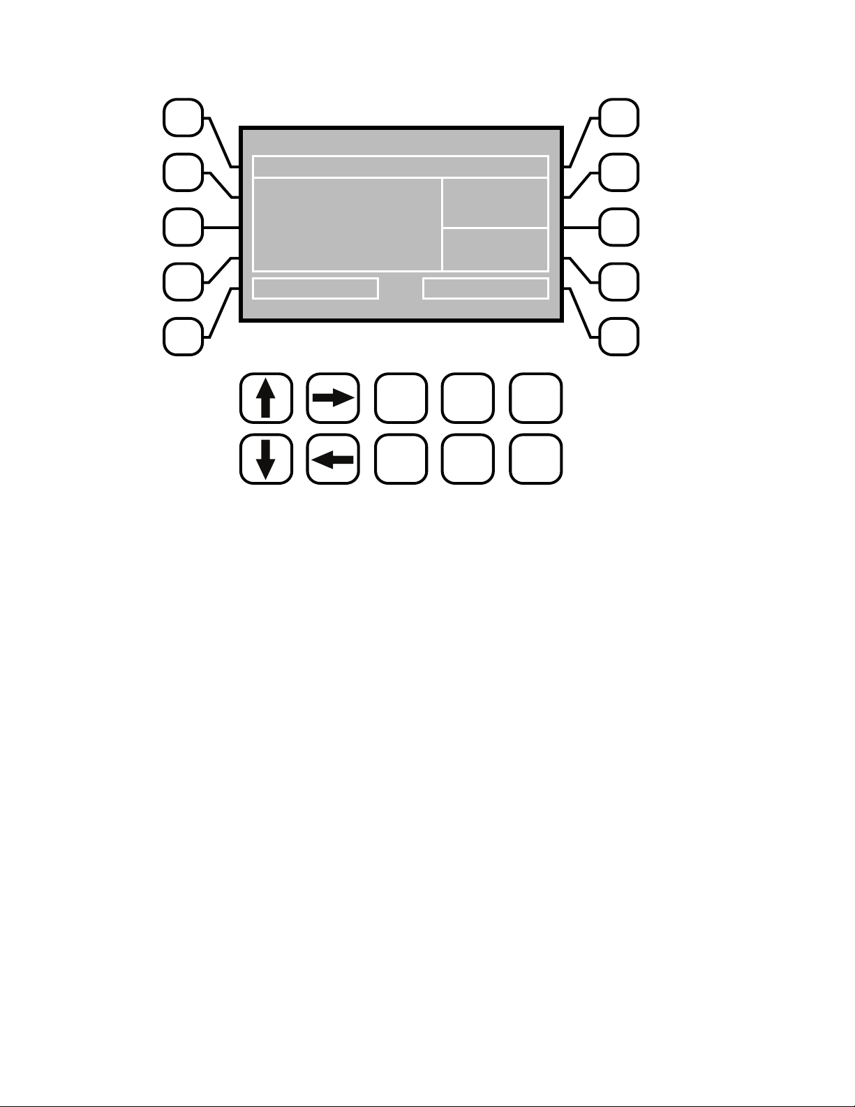
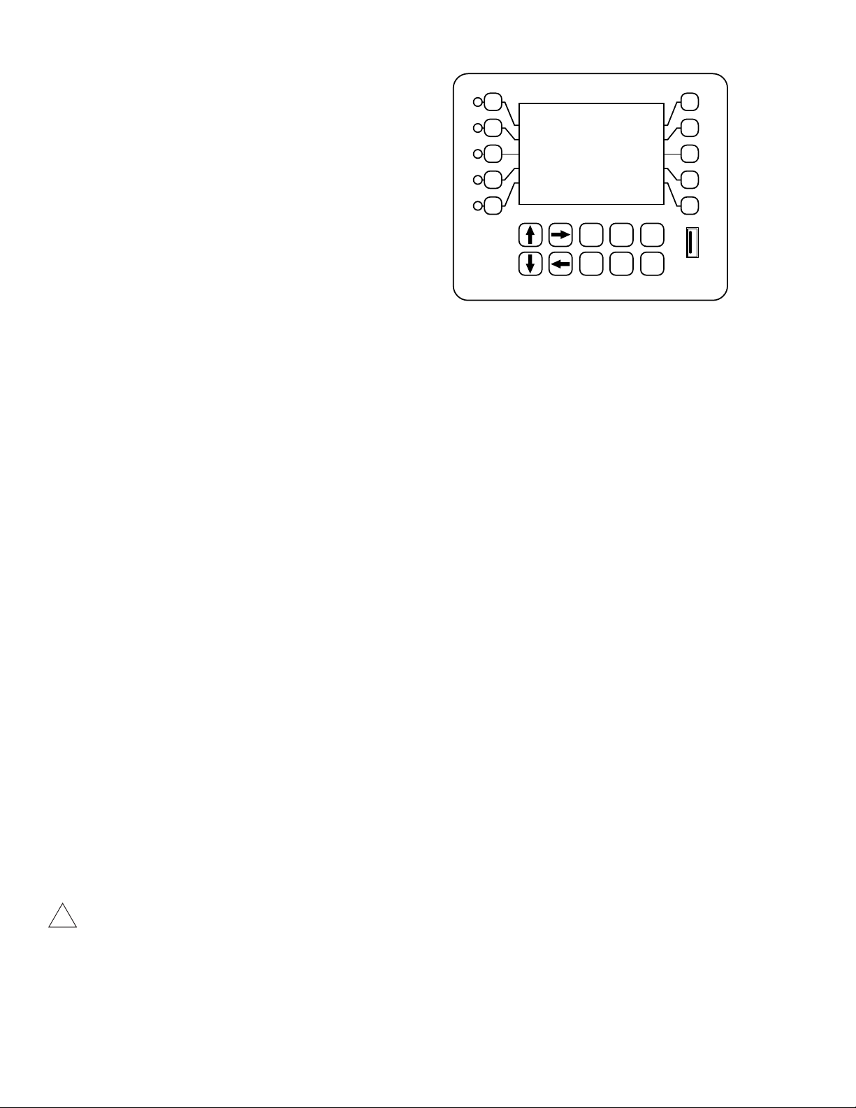
IV. Front Panel Description
3
4
5
2
1
8
9
0
7
6
SET UP
RUN
CANCEL HELP BACK
ENTER HOME
ACI MEGATRON
SYS1: TOWER CARD 1
COND 1,400 uS/cm
pH 7.2
ORP 375 mV
SYSTEM OK <HOT KEY>
STATUS
SYS OK
TEMP: 72.1F
FLOW: ON
Thursday, August 29, 2013 02:24:10 PM (Wk1)
NUMBER Keys- Used to enter new values in the SET UP mode and to access desired sub menus.
SET UP/RUN - System initializes into RUN mode. Press this key to put the controller in SET UP
Mode and see HOME menu page.
ENTER - Used to log a changed value into program.
HOME - Used to go back to the HOME menu page.
CANCEL - Used to cancel a pop-up screen if no change is desired.
HELP - Used to access help screens.
BACK - Used to go back to last menu screen viewed or clear values keyed in that are not
wanted.
The bottom right box in the RUN screen mode is a hot key that will take you directly to a particular menu
screen. The default is the RELAY status menu but this can be changed by navigating to the desired screen
and pressing the HELP button. Follow the on-screen instructions to set the new hot key location.

11
V.SystemOperationOverview
Operation
MegaTronXS controllers have two modes of operation, RUN and SET-UP.
RUN - This mode is for normal operation. In the RUN mode the display will show each system’s parameters.
or changed in the RUN mode. Readings are updated every 6 seconds on the screen while in the RUN mode.
SET-UP - This mode is used to make adjustments to settings and readings on the controller. To access the
SET UP mode from the RUN screen, press the SETUP/RUN key.
VI.MenuNavigation
To access the menus press the Set Up / Run key on the front panel. This takes you to the Home menu.
MegaTronXS controller’s menus are easily navigated by pressing the associated number key next to a menu
box on the screen. Once you have stepped through the sub menus to reach a point at which a value or
selection is made a Pop-up window will appear prompting you to enter a desired value or selection.
NOTE: When entering new numeric values, enter all available digits (characters).
1. Home Menu
From the HOME menu select the desired menu.
The menu name explains what parameters can be
programmed in the menu.
SET POINTS - Setting control set points for pressure.
CALIBRATION - Calibrating pressure.
TIMERS - Menu for selecting type and settings for all present feed timers.
CUSTOMIZE
ALARMS - View current alarms.
DAY/TIME - Menu for setting date and time.
CONFIGURE
switch, contrast, temperature scale.
HISTORY - Allows for view history on board in a graph form.
WATER METER
RELAYS - Menu for resetting accumulated “ON” times and manual relay activation.
>HOME SETUP<
SETPOINTS DATE/TIME
CALIBRATION CONFIGURE
TIMERS HISTORY
CUSTOMIZE WATER METER
ALARMS RELAYS

12
2. Set Points
SET POINTS - For setting the relay set points for the
available analog probe readings such as 4-20 mA
inputs for pressure.
NOTE: In the Setpoints pop-up screen the direction (Rising or Falling) of the setpoint can also be set. If
setpoint. The pump output relay will remain activated until the PSI reading falls below the setpoint by the
the PSI reading falls below the setpoint. The pump output relay will remain activated until the PSI reading
2.5 AuxInputs
Auxiliary inputs are the digital inputs for optional Flow Switch and other digital inputs such as low drum level
both or none.
Note: Digital inputs can have the direction selected
between OPEN or CLOSED as the alarm polarity. If
set for CLOSED the input will be in alarm when it sees
a closed contact.
2.6 4-20mAOut
Units with a 4-20mA output option will have a menu for setting up the 4-20mA output. The 4mA and 20mA
PSI.
SIGNAL SOURCE - Select which probe reading the
mA will use as its reading source.
4 mA VALUE - What the 4mA signal equals
20mAVALUE - What the 20mA signal equals on the
assigned signal sources scale.
2.7 4-20mAInput
SET POINT - What reading turns the relay on
DIFFERENTIAL - Amount reading changes by before
HIGH ALARM - What reading generates a High alarm
LOW ALARM - What reading generates a Low alarm
>SYSTEM 1 SET POINTS<
mA OUT
mA IN
AUX INPUTS
>SYSTEM 1 DIGITAL INPUTS ALARM<
ALARM NOTIFICATION DIGITAL 1
FLOW SW = DISPLAY DIGITAL 2
DIGITAL 1 = DISPLAY DIGITAL 3
DIGITAL 4
FLOW ALARM DIGITAL 5
>OUT 1 SETUP<
SIGNAL SOURCE
4mA VALUE
20mA VALUE
>mA INPUT 1 SETPOINT<
SET POINT
DIFFERENTIAL
HIGH ALARM
LOW ALARM

13
3. Calibration
Calibration is for adjusting the displayed value of a probes reading to match your tester or known solution.
All MegaTronXS controllers are factory calibrated. All units are shipped with the date preset, and the clock
the instructions listed below.
3.3 4-20mAOutputCalibration
4-20mA outputs can be calibrated to insure that the
output generated by the controller and received by the
external device match. With a volt meter connected
across the out and return wires (see page 24) of the
4-20mA output channel to be calibrated go into the
output’s Low or High calibration.
The number displayed in the Calibration dialog box
can range from 0-4095 with 800 equal to 0 mA output
and 4030 equal to 20 mA. This number range of
0-4095 is the raw digital to analog (D/A) values and is
strictly used for a reference. The D / A numbers you
get will vary based on your installation conditions.
While in the High or Low calibration pop-up screen use
the up and down arrows to change the output value
being read with the volt meter. Adjust the High value
for the 20 mA reading and the Low value for the 4 mA
value.
3.4 4-20mAInputCalibration
4-20mA inputs can be calibrated to insure that the input seen by the controller from the external device match.
It also allows for setting the 4-20mA input into a number range that relates to the value being read.
Select the Input to be calibrated
The 20mA and 4mA values are where the controller’s
raw analog to digital value is adjusted to match a 20mA
(full scale) and 4mA (bottom of scale) signal from the
external device inputting the 4-20mA input. The external
device must be connected to the controller and showing
either full scale or bottom of scale when calibrating
each. The number shown along with either the 20mA
or 4mA while calibrating is the raw A/D value and is only
>CURRENT LOOP CALIBRATION<
OUTPUT 1
OUTPUT 2
>mA OUTPUT 1 CALIBRATION<
HIGH 4030
LOW 800
>mA OUTPUT 1 CALIBRATION<
OUTPUT 1 CAL HIGH
4000
Use Up/Down arrows to change
Use Enter to save value
>CURRENT LOOP CALIBRATION<
INPUT 1
INPUT 2
>mA INPUT 1 CALIBRATION<
20mA 5500
4mA 1100
MAX 200
LOW 0
OFFSET FACTORY DEF.

14
a reference. A 20mA input should be around 5500 and 4mA around 1100. If the A/D numbers are not in this
range check input device.
The MAX and LOW calibration inputs are for telling the controller what to display for a 20mA input and a 4mA
input. For example if the input is a drum level sensor monitoring a 55 gallon drum the value for MAX should
be 55 and LOW should be 0. The controller then displays a number automatically ranging between 55 and
0 based on the input value. The units of measure (gallons for example) is set in the Customize menu from
the Home page.
OFFSET - Changes the current displayed value of the 4-20mA input reading to allow for a manual 1pt
calibration of the displayed value.
FACTORY DEFAULT - If the 20mA or 4mA calibration has been incorrectly set (not at 4 or 20) this will reset
the settings back to a factory value for 4 and 20.
4. Timer
A unit may have up to (1) timer standard for each system on a controller. All timers are associated with their
system, so for a % of post bleed timer looks at the bleed of that system.
TIMER - Select the type (28-day, pulse, limit, percent or
percent of post blowdown) as well as the run times of
each timer available per system.
4.1 Timer Type Selection
A pop-up screen lets you scroll through the various timer types available.
* Pulse - A water meter activated timer
* Limit - Feed with bleed with a maximum run time or
limit for one bleed cycle.
Recycle - A continuous recycle timer with ON and OFF
settings.
* Percent Post Bleed - For feed after bleed for a
settable percentage of the bleed time with a maximum
run time.
28-Day - A biocide or event timer.
* Main timer types used
4.2 Timer Set Up
Each timer type selected will have its own unique Set
the type of timer selected. The page displayed before
entering the Set Up menu of a timer provides an overall
review of the timers current settings.
>SYSTEM 1 TIMER<
TIMER 1
>SYSTEM 1 TIMER 1 SET UP<
>SET TIMER TYPE (PULSE)<
-> PULSE
USE UP/DOWN KEYS TO CHANGE
PRESS ENTER TO ACCEPT
SET UP TIMER TYPE
>SYSTEM 1 TIMER 1 SET UP<
TIMER TYPE: PULSE
GALLONS: 10
RUN TIME (MM:SS): 01:00
INPUT: WATER METER 1
SET UP TIMER TYPE

15
4.3 Recycle Timer
ON CYCLE
timer is to be on.
OFF CYCLE - The amount of time that the cycle is
going to be on.
ON/OFF TIMER - This is the displayed count down of
time for the cycle the timer is in.
4.7 28-DayTimer
Each 28-day timer has Program 1-4 for programming the various feed times. While the programming steps
for four programs are the same each can have it’s own independent settings.
WEEKS - The week(s) that the timer is to feed.
DAYS - The day(s) that the timer is to feed.
START - The time of day for the timer to start.
RUN - How long the timer is to run.
FEED LOCK - Which other system timer to lockout
during this timer’s run time.
FLOW LOCK
ignore it for this timer.
5. Customize
The user can also setup the Notepad for each system and 4-20mA Input’s name and unit of measurement.
RUN SCREEN - Allows the user to select what will be
shown on the screen while the controller is in the RUN
mode. Like displaying temperature readings, water
meter totals for a particular system or the conductivity
units of measure.
NOTE: When entering values for custom names use the numerical keys for numbers and the up / down
arrows to scroll through all the characters of a key board. Press the right arrow to advance the curser after
setting a desired value. Press the Help button to place the last entered character into the new cursor space
to speed up the process. The Help button will also jump advance through the characters.
5.1 Notepad
with ten notepad items. The NOTEPAD is ideal for setting up and storing into the controller’s history the items
typically tested for reporting a service call. The Notepad items come with no names but when an individual
note is selected a menu for setting it appears.
>SYSTEM 1 TIMER 1 CHANGE<
ON CYCLE (HH:MM)
OFF CYCLE (HH:MM)
OFF TIMER (HH:MM:SS): 0:10:40
>SYSTEM 1 TIMER 1 CHANGE<
WEEKS
DAYS FEED LOCK
START TIME
RUN TIME FLOW LOCK
>CUSTOMIZE<
UNIT NAMES
RELAY NAMES NOTEPAD
SYSTEM 1 NAME pH INDEX
mA IN
RUN SCREEN

16
NAME -
your own.
NUMBER - Set the number range.
UNITS - Set the units of measurement.
ALARMS - Set Hi/Low alarm points and how frequently
a new value is expected to be manually enter via the
History menu.
5.2 mAInputs
NAME - Name the input.
UNITS - Set the units of measurement.
NUMBER - Set the number range.
5.4 RunScreen
This lets you customize various aspects of the RUN screen.
MAIN SCREEN - Customize what is displayed on the
RUN screen.
SCREENS SHOWN - Pick if the mA input & Aux Flow
screens are scrolled.
CYCLE TIME - The amount of time between screen
scrolls.
COND UNITS - Select the units of measure to be
displayed with the conductivity reading.
6. Alarms
ALARMS - Shows any current alarms.
7. DateandTimeSetUp
DATE AND TIME - For setting the date, time, day and
week on the controller.
>NOTEPAD SYS 1 NOTE 1<
NAME
NUMBER
UNITS
ALARMS
>mA INPUT 1 CUSTOMIZE<
NAME
UNITS
NUMBER
>RUN SCREEN<
MAIN SCREEN
SCREENS SHOWN
CYCLE TIME
COND UNITS
>ALARMS<
SYS 1 ALARMS
>SET DATE AND TIMES<
SET DATE
SET TIME
SET DAY
SET WEEK
Friday May 14, 2005 03:04:56

17
8. Congure
inputs, history time stamps, factory set-up and system information.
CONTRAST - This screen allows for adjusting the
display contrast.
FLOW SW
FACTORY - A factory only menu
TEMP SCALE - Set Celsius or Fahrenheit
HISTORY - Sets the history time stamp interval.
SYS INFO
8.1 Password
ADMIN PASSWORD - The administrator password
gives access to all menus except factory set up.
USER PASSWORD - The user password allows the
user to access HOME menus that are made available
in USER SET UP.
8.2 Relays
CONFIGURE RELAYS - This menu lets you choose a
Main Action or function (timer 1, conductivity, alarms
etc...) to activates a relay.
A pop-up screen appears with a list of all available
activation functions to arrow through.
Additional relay logic is available with up to 3 additional Activators and up to 4 Disablers allowing multiple
functions to activate the same relay and multiple functions to prevent the relay from coming on. There is
also a Daily Max amount of time that a relay can be on. If a relay is on for the max amount it does not let
the relay come on anymore that day. (A 24 hour clock is used for the day with midnight being the start of
the day). The Delay setting is the amount of time a control function must come on before the relay will
point or alarm.
8.3 History
This menu is used to set the history “time stamp” interval, the water meter daily history starting hour and the
alarm delay period.
INTERVAL - The amount of time between each history
time stamp for probe readings.
W/M HOUR - The time of day that the daily water
meter history cycle is to start.
ALARM DELAY - The amount of time an alarm has to
be on before it is recognized as an alarm.
>CONFIGURE<
PASSWORD CONTRAST
RELAYS TEMP SCALE
NETWORK
HISTORY SYS INFO
FLOW SW FACTORY
>CONFIGURE PASSWORDS<
ADMIN PASSWORD
USER PASSWORD
USER SET UP
>RELAY 1 SETUP<
MAIN ACTION DISABLE 1
ACTIVATOR 2 DISABLE 2
ACTIVATOR 3 DISABLE 3
ACTIVATOR 4 DISABLE 4
DELAY DAILY MAX
>CONFIGURE HISTORY<
INTERVAL
W/M HOUR
ALARM DELAY

18
8.4 Flow Switch
8.5 Contrast
This menu is used to adjust the contrast of the display.
8.6 Temperature Scale
This menu is used to select the type of temperature scale to display.
8.7 Network (if applicable)
The Network menu is used when a controller is being remotely communicated with either a local network
connection or over the internet on the Web Advantage server.
NETWORK - This menu is used for setting up the
remote WebAdvantage communications and is
covered in a separate manual.
8.8 System Information
serial number.
9. History
The onboard history allows for viewing the history of the probe readings, relay activations, key-pad activity,
calibrations, water meter hourly and daily logs and alarms for each system present. It is also where Notepad
data is entered and reviewed. An initial overview page is displayed showing your current sample interval, the
calculated number of days the unit can keep probe history for before losing the oldest. The number of sensor
samples and relay/alarm events and Notepad entries currently stored is also displayed.
NOTE: The history can be reset by going to the
interval. After the new sample interval has been set
the onboard history is reset.
>CONFIGURE NETWORK<
IP ADDRESS HTTP REMOTE
IP MASK FTP
GATEWAY RESET
SERVER
HTTP LOCAL
>HOME REVIEW<
SYSTEM 1 Sample Time: 5 MIN
(Length 164.62 days)
Sensor Samples
882
Relay/Alarm Events
323
Notepad Entries

19
9.1 Viewing History
RELAY LOGS - Relay activations displayed in a log
form. Arrow up to advance through the log.
ALARM LOG - Alarm activations in log form.
SENSOR HISTORY - For selecting the parameters
and viewing of a given probe reading’s history in log or
graph form.
EVENT LOG - Displays various activities.
9.2 Notepad Entries
The Notepad section under History is where the user
goes to enter new values for the customized notepad
items. Each individual notepad item’s manually
entered entries are stored in the units history and
can be reviewed in log or graph form after 4 or more
values have been entered.
11. Relays
STATUS - Allows for viewing accumulated relay ON
times, temporary forcing relays ON or OFF or seeing
which relay is on.
RESET - Allows the accumulated run time of a
particular relay to be reset to zero.
FORCE - Allows a relay to be manually forced ON
for a single event from 0-99 minutes. When the event
is over the relay goes back to it’s normal automatic
control.
In the STATUS view the accumulated ON time is
shown along with the main activator, custom name and
current status:
ON = Relay on by relay activators
ON-A = Relay activated by activator other than main
action
H-ON = Relay manually forced on
>HISTORY<
RELAY LOGS WATER METER
ALARM LOGS
SENSOR HISTORY
EVENT LOG
NOTEPAD
>NOTEPAD: SYS 1 NOTE 1<
ENTER VALUE Total Hardness
LOG 8 Entries
GRAPH
517.2 Hrs to Alarm
>RELAYS<
STATUS
RESET
FORCE
>RELAY STATUS<
R01: ON 006:30:30
SYS1 COND BLEED
R02: OFF 008:56:35
SYS1 pH
R03: OFF-T 011:00:10
SYS1 TIMER1 INH
R04: OFF 007:00:00
SYS1 TIMER2 BIO1
R05: OFF 008:10:30
SYS1 TIMER3 BIO2
20
VII. USB Functions
The XS is capable of transferring information
using a FAT formatted USB drive. The XS has three
main functions that it can perform using the USB.
(1) Upgrade XS Firmware from USB Drive
(2) Save XS Log Data to USB Drive
(3) Clone User Settings between XS units.
Upgrade XS Firmware
USB DRIVE DETECTED pop-up window will appear. Use the up and down arrows to choose the “Update
Firmware” selection. Press ENTER. It may take a few minutes for the update process to complete. Do not
will automatically reboot. Once the system reboots, the USB DRIVE DETECTED screen will re-appear.
Remove the USB Drive and this window will close.
SaveXSLogDatatoUSB
History there is a selection called Save Format. The WebAdvantage format is the default for then uploading
history to WebAdvantage for cloud storage and graphing. Change to Comma Separated if using with Excel.
To transfer the contents of the XS history logs to the USB drive, plug a USB drive in to the XS USB port. The
USB DRIVE DETECTED pop-up window will appear. Use the up and down arrows to choose the “History-
>USB” selection. Press ENTER. It may take a few minutes for the process to complete. Status will be displayed
on the screen to show the percent completed of each log record type. Once the log is completely stored, the
Cloning an XS
The XS has the ability to copy the User Settings from one XS to another. This process is referred to as
cloning. To clone your XS, insert the USB drive into the XS with settings you want to save for cloning. Once
“CONFIG.BIN”. The pop-up window will close when the copy is completed.
Take the USB drive and plug it in to the XS that you would like to copy the User Settings to. When the
selection. Press ENTER. The User Data will be loaded in to the XS from the USB drive. Once the pop-up
window closes, the cloning is completed.
Warning: 1.Notallcustomizednamesaresaved.
2.USBdrivesmustbeFATformattedtoworkcorrectly.
!
USB
Port
3
4
5
2
1
8
9
0
7
6
SET UP
RUN
CANCEL HELP BACK
ENTER HOME
Table of contents
Other Advantage Controls Industrial Equipment manuals

Popular Industrial Equipment manuals by other brands


Siemens
Siemens FM 450-1 Equipment manual

ATI Technologies
ATI Technologies QC-210 product manual

Eaton
Eaton DILM32-X L Series Instruction leaflet

TTM
TTM MAG 250 Installation, Operating and Maintenance Instruction

Endress+Hauser
Endress+Hauser Liquiport 2000 operating manual

ABB
ABB HT578689 Operation manual


