Radicon J Series User manual

www.radicon.com
Series J Shaft Mounted Gearbox
Technical
Up to - 600kW /57,000 Nm
Industrial Gearbox
CJ-1.00GBD0111

PRODUCTS IN THE RANGE
We can create custom engineered transmission solutions of any size and conguration.
Serving an entire spectrum of mechanical drive applications from food, energy, mining and metal; to automotive,
aerospace and marine propulsion, we are here to make a positive difference to the supply of drive solutions.
We offer a wide range of repair services and many years experience of repairing
demanding and highly critical transmissions in numerous industries.
Series X
Cone Ring
Pin and bush
elastomer coupling
Series X
Torque Limiter
Overload protection
device
Series J
Shaft mounted
helical speed
reducers
Series C
Right angle drive
helical worm geared
motors & reducers
Series BD
Screwjack worm
gear unit
Series G
Helical parallel shaft
& bevel helical right
angle drive gear
units
Series X
Grid
Double exing steel
grid coupling
Series M
In-line helical geared
motors & reducers
Series H
Large helical parallel
shaft & bevel helical
right angle drive units
Roloid Gear Pump
Lubrication and uid
transportation pump
Series BS
Worm gear unit
Series X
Nylicon
Gear coupling with
nylon sleeve
Series A
Worm Gear units
and geared motors
in single & double
reduction types
Series X
Gear
Torsionally rigid,
high torque coupling
Series K
Right angle helical
bevel helical geared
motors & reducers
Series F
Parallel angle helical
bevel helical geared
motors & reducers
SERIES J

www.radicon.com
www.benzlers.com
ASIA
Elecon. Engineering
Company Ltd.
Anand Sojitra Road
Vallabh Vidyanagar
388120 Gujarat
India
Tel: +91 2692 31170
Fax: +91 2692 36559
DENMARK
Benzler Transmission A/S
Fuglebævej 3D
DK-2770 Kastrup,
Denmark
Tel: +45 36 34 03 00
Fax: +45 36 77 02 42
EUROPE
Benzler TBA BV
Jachthavenweg 2
NL-5928 NT Venlo
Netherlands & the rest of Europe
Tel: +31 77 324 59 00
Fax: +31 77 324 59 01
Austria
Tel: +43 7 229 618 91
Fax: +43 7 229 618 84
Germany
Tel: 0800 350 40 00
Fax: 0800 350 40 01
FINLAND
Oy Benzler AB
Vanha Talvitie 3C
FI-00580 Helsingfors,
Finland
Tel: +358 9 340 1716
Fax: +358 9 340 1761
SWEDEN & NORWAY
AB Benzlers
Box 922 (Landskronavägen 1)
251 09 Helsingborg
Sweden
Tel: +46 42 18 68 00
Fax: +46 42 21 88 03
THAILAND
Radicon Transmission
(Thailand) Ltd
700/43 Moo 6
Amata Nakorn Industrial Estate
Tumbol Klongtumru
Muang,
Chonburi
20000
Thailand
Tel: +66 3845 9044
Fax: +66 3821 3655
UNITED KINGDOM
Radicon Transmission
UK Ltd
Park Road
Lockwood, Hudderseld
West Yorkshire, HD4 5DD
Tel: +44 (0) 1484 465 800
Fax: +44 (0) 1484 465 801
USA
Radicon Transmission USA
240 East 12th Street
Traverse City
Michigan
49684
USA
Tel: +1 888 994 2663
Fax: +1 888 907 2663
Contacts
SERIES J

ATEX
Compliance Assured
Total compliance with the ATEX Directive safeguarding the use of
industrial equipment in potentially explosive atmospheres is
assured for users of our geared products.
Certification is available for standard gearboxes and geared
motors with badging displaying the CE Mark and the Ex mark,
name and location of the manufacturer, designation of series or
type, serial number, year of manufacture, Ex symbol and
equipment group/category.
ATEX directive 94/9/EC (also known as ATEX 95 or ATEX 100A)
and the CE Marking Directive are enforced in all EC member
states. Compliance is compulsory for designers, manufacturers or
suppliers of electrical and non-electrical equipment for use in
potentially explosive atmospheres created by the presence of
flammable gases, vapours, mists or dusts.
Ex compliant standard gearboxes can be supplied against Groups
2 or 3 for surface industries in designated hazardous location
Zones 1 and 2 for gases, vapours and mists; and in Zones 21 and
22 for dusts.
694-87 ATEX Brochure Insert:694-87 ATEX Brochure Insert 21/6/07 10:08 Page 1

SERIES J

2
SERIES J
CONTENTS
0203
Series J Shaftmounted Speed Reducers, General Description 4
Unit Designations 5
Selection Procedure 6 - 7
Power ratings / Thermal power ratings
1-stage 8
2-stage 15:1 9 - 10
2-stage 20:1 11
2-stage 25:1 12 - 13
Dimensions
J 11 - 71 1-stage 14 - 15
J 100 - 125 1-stage 16 - 17
J 12 - 72 2-stage 18 - 19
J 100 - 190 2-stage 20 - 21
Selection of V-belt drives
Power ratings V-belt transmissions 22 - 52
Accessories
Threaded holes at gear house sides 53
Shaft bushings 54
Machine shaft dimensions 55 - 57
KIBO Tapered bushing 58 - 59
Motor mounts 60 - 61
Cooler fan/electric and oil cooler 62
Torque arm, Shock absorber and Overload protection 63
Shrink disc, Protection cover, V-belt protection cover 64
Hydraulic motors, Vertically mounted reducers 65
Backstop
Backstop mounting 66 - 67
Installation and Maintenance
Mounting Positions 68
Installation 68
Lubrication instructions 69

3
SERIES J
Series J Shaft Mounted Speed Reducers are high quality products, submitted to intense quality control and
manufactured with the highest precision.
— Worldwide after sales service
— 19 types up to 600 kW, 57000 Nm
— Wide range of standard accessories
— High efficiency
— Long gear and bearing lifetime
— All mounting positions possible
— Easy to mount
— Easy to change speed through change of V-belt transmission
— Space saving
— Low noise level
— Easy to service, due to standard components
GENERAL DESCRIPTION
* Not standard for the smallest sizes of single and double reducers.
The shaft sleeve is supplied with
tapped holes for dismounting the
reducer as well as locking the
reducer to the shaft.*
The input shaft diameter corre-
sponds to IEC standard for motor
shafts, thus simplifying standardi-
zation of V-belt pulleys and
couplings. Locating shoulder
provided for pulleys and
couplings.
The input shaft is supplied with
tapped hole for fitting V-belt pulley
or locking washer for V-belt pulley.
All housing contact surfaces are
fine milled thus eliminating the
necessity for gaskets and
possible oil leaks.
KIBO
®
- One of the most cost
efficient dismounting methods
that is available on the market,
patented by us is available as a
standard accessory to every
Series J shaft mounted speed
reducer.
Modern heat treatment of high quality
gives gear wheel and pinions the hard
wearing surface and tough core
necessary to handle harsh duties.
Manufacturing tolerances comply to
DIN and AGMA specifications. Helix
angle
and small modules give more teeth in
mesh for smooth and quiet running.
High quality bearings selected for long
service life.
Backstop options are available for all
double reduction units (For single
stage units on special request).
High quality close grained cast iron
housing with maximum rigidity and low
weight saves space.
Torque arm bracket will stand up
to tough reversible shock load
applications allowing for two torque
arms to be mounted in opposite
directions.
0201

4
SERIES J
*
1 2 3 4 5 6 7 8 9 10 11 12 13 14 15 16 17 18 19 20
*
1 - SERIES J
SHAFT MOUNTED GEARS
RANGE J
13 - INPUTSHAFT
- - STANDARD
M - MC - IEC FLANGE *
H - HD - HYDRAULIC MOTOR *
X - SPECIAL
* SPECIFY MOTOR SIZE
10, 11, 12 - BORE DIAMETER
eg 0 3 5
1 2 5
See page 54
6, 7 - NOMINAL
OVERALL RATIO
eg - 5 Standard single stage
1 5 Standard double stage
2 0 Standard double stage
2 5 Standard double stage
See pages 8, 9, 10 , 11, 12 & 13
5 - REVISION NUMBER
- Initial Version
- - NO BACKSTOP
B V LEFT ROTATION (Counter-Clockwise)
B H RIGHT ROTATION (Clockwise)
EXAMPLE J 1 1 0 - 2 0 - - 1 1 0 - 2 - - - - - -
20 - ADDITIONAL FEATURES
- - NONE REQUIRED
P - PULLEY OR/AND MOTOR
M - PRE-REDUCER TYPE M
THIS PAGE MAY BE PHOTOCOPIED ALLOWING THE CUSTOMER TO ENTER THEIR ORDER
UNIT DESIGNATIONS
9 -OUTPUT OPTIONS
- - STANDARD HOLLOW SHAFT
K - KIBO See Hollow shaft bores page 54
S - SHRINK DISC ST
X - SHRINK DISC STX
14 - MOUNTING POSITIONS
2 - H2 STANDARD
5 - H5 VERTICAL UP
6 - H6 VERTICAL DOWN
1 - H1 3 - H3
X - SPECIAL * 4 - H4
SEE PAGE 68
* SPECIFY INCLINATION ETC
18 - PAINT OPTIONS
- - STANDARD
1 - SPECIAL COLOUR (ALKYD)*
2 - TWO PACK HIGH SOLID
3 - SPECIAL*
* SPECIFY TYPE AND COLOUR
19 - SEAL OPTIONS
- - STANDARD
L - LABYRINTH SEALS
T - VITON
2, 3, 4 - SIZE OF UNIT
J 1 1 A
2 1 A
3 1 A
5 1 A
7 1 A
1 1 B
2 1 B
3 1 B
5 1 B
7 1 B
J 1 2 A
2 2 A
3 2 A
5 2 A
7 2 A
1 2 B
2 2 B
3 2 B
5 2 B
7 2 B
J 1 0 0
110
125
140
160
190
8 -TORQUE ARM
eg - STANDARD R
1 STD RL (BALL JOINT)
2 STD RR (SHOCK ABSORBER)
3 STD RO (OVERLOAD PROTECTION)
0201
See page 64
- NO ADDITIONAL COOLING
E ELECTRIC FAN
C OIL COOLER
15, 16 - BACKSTOP
17 - COOLING OPTIONS (ONLY J100 - 190)

5
SERIES J
Definition of service factor
The torque ratings apply to service factor fb = 1,0.
The service factor fb = 1,0 gives continual operation 4 to
8 hours a day at a uniform load without shocks and with
10 to 200 starts an hour. The moment of inertia of the dri-
ven machines is less than 20 % of the electric motor iner-
tia and occasional peak torque may not exceed 1,8
times the torque rating. For other running conditions com-
pensate with service factors according to tables.
Definitions
P
e
= Demand of power from driven machine (kW)
T
e
= Demand of torque from driven machine (Nm)
n
e
= Speed on driven machine (min
-1
)
T
emax
= Max peak torque from driven machine (Nm)
T2 = Max allowed torque at service factor fb =1,0
Thermal rating
Thermal rating is the power in kW (without service factor)
that the gear unit can transmit at continuous operation in
1 hour or more without getting overheated.
Control of thermal rating is essential because if the service
generates more heat than it can emit, severe damage may
occur.
Thermal rating does not need to be controlled if the duty time
is less than 1 hour.
When the duty time is longer than 1 hour the gear unit and
cooling method must be selected so that the drive
transmission has enough thermal rating.
In the tables the thermal rating Pt is given in the following
conditions:
- 25 °C ambient temperature
- 0 to 750 m altitude above sea level
- Ambient air velocity between 1,4 and 3,7 m/s
(sheltered outdoor space)
- Continuous operation
For sizes J100 to J190 standardized solutions for cooling
of the gears are available. An electric fan can be mounted
on the gear. The gear may also be provided with a
water-based oil cooler (contact our Application Engineers for
selection of correct size).
1) At V-belt drive when the motor is placed beside the gear,
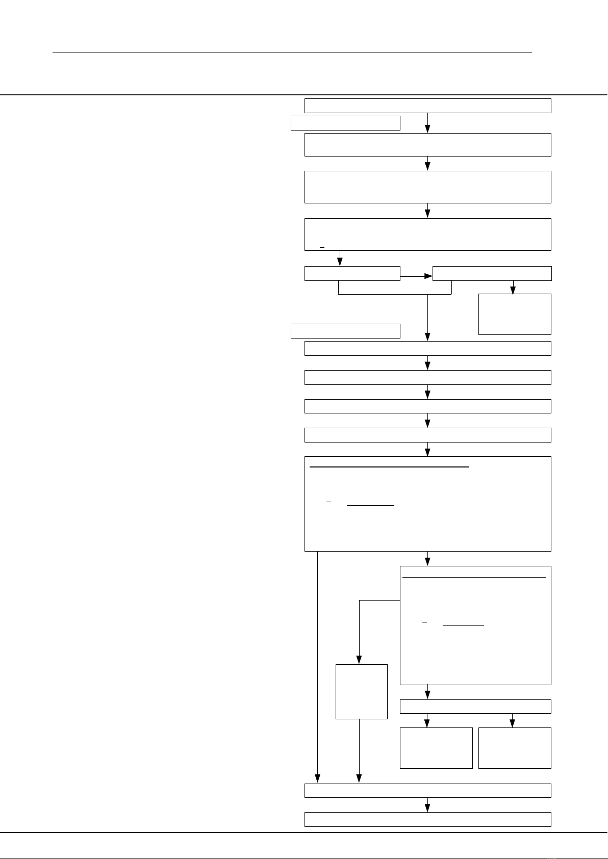
check the operation according to the diagram.
Determine the demand of power (P
e
kW) or torque (T
e
Nm) and
speed (n
e
min
-1
) to the driven machine by calculation or measuring
Based on type of load / driven machine, operating hours a day
and number of starts an hour select service factor (fb) according
to table 1 and table 2
Select Series J gear from power rating tables on pages 22 - 52.
Select the mechanical rating:
T2 > fb x T
e
Nm
Shock load ?
Select operation time factor fu according to table 6
Control of thermal rating without extra cooling
Check that the thermal rating of the selected gear Pt is bigger than
required thermal rating:
Pt > P
e
ft x fa x fv x fu
Thermal rating Pt for mineral and synthetic oil are in the tables on
pages 8 - 13. The values are valid for horizontal applications. For
vertical applications 0,8 x Pt is used.
Control of thermal rating with electric fan
Check that the thermal rating of the
selected gear Pt is bigger than required
thermal rating:
Pt > P
e
ft x fa x fu
Thermal rating Pt for mineral and synthetic
oil with fan cooling are in tables on pages
8 -13. The values are valid for horizontal
applications. For vertical application
0,8 x Pt is used.
Can a water based oil cooler be used ?
Order gear with accessories according to 20-digit figure code page 5.
Order a water
based
oil cooler from us
Use a larger gear
size or contact our
Application
Engineers
Order an
electric fan
from us
No, cooling with fan is not enough
Mechanical Rating
Yes
Yes
NoNo
Yes
Start
No, extra cooling is needed
1)
SELECTION PROCEDURE
Select accessories (V-belt drive, motor mount, KIBO, backstop)
No
Yes
Yes
Select ambient air velocity factor fv according to table 5
Select altitude factor fa according to table 4
Select ambient temperature factor ft according to table 3
Thermal Rating
Use a larger gear
size or contact our
Application
Engineers
T
emax
< 1,8 x T2
0203

6
SERIES J
Table 2. Description of load classifications
Load
classification
Example
Description
Mass acceleration factor
Load
classifications
Uniform
U
Uniform
Ua
Moderate
M
Heavy
H
Mass acceleration factor = all external moments of inertia *
moment of inertia of driving motor
Service factors
Table 1. Service factor fb
Daily operation 4 hours 8 hours 16 hours 24 hours
Starts per hour <10 10-200 >200 <10 10-200 >200 <10 10-200 >200 <10 10-200 >200
Table 6. Operation time factor fu (All cooling methods)Table 5. Ambient air velocity factor fv (Without electric fan)
Table 4. Altitude factor fa (Only for air cooling)Table 3. Ambient temperature factor ft (All cooling methods)
Operation time per each hour Factor fu
Altitude m Factor faAmbient temperature °C Factor ft
100% 1.00
80% 1.05
60% 1.15
40% 1.35
20% 1.80
Air velocity V ref
m/s Environment
Vref < 0.5 Small confined space 0.53
0.5 < Vref < 1.4 Large indoor space 0.71
1.4 < Vref < 3.7 Sheltered outdoor space 1.00
Vref > 3.7 Outdoor space 1.35
10°C 1.17
15°C 1.12
20°C 1.06
25°C 1.00
30°C 0.94
35°C 0.88
40°C 0.81
45°C 0.74
50°C 0.66
* calculated with reference to the motor speed
0203
SELECTION PROCEDURE
U 0.8 0.9 1.0 0.9 1.0 1.1 1.1 1.2 1.3 1.3 1.4 1.5
Ua 1.1 1.2 1.3 1.1 1.3 1.5 1.3 1.5 1.6 1.4 1.6 1.8
M 1.3 1.4 1.6 1.3 1.6 1.8 1.4 1.7 1.9 1.5 1.8 2.0
H 1.5 1.6 1.8 1.6 1.8 2.0 1.7 1.9 2.1 1.8 2.0 2.2
Larger conveyors. Reciprocating pumps with 3 or
more cylinders.
Agitators and mixers for media with high viscosity and
/ or solid particles.
Larger conveyors. Reciprocating pumps with 3 or
more cylinders.
Agitators and mixers for media with high viscosity and
/ or solid particles
Heavy agitators and mixers. Reciprocating pumps
with 1 or 2 cylinders.
Crushers, mills and presses. Vibrators and shakers
Uniform loaded conveyors and elevators. Centrifugal
pumps and fans. Agitators and mixers for liquids and
semi-liquids without solid particles.
Machines with uniform load and no shocks
Mass acceleration factor < 0.2
Machines with small shocks and small
variations in load
Mass acceleration factor < 1
Machines with moderate shocks and
variable load
Mass acceleration factor < 3
Machines with very heavy shocks and
large masses to be accelerated
Mass acceleration factor < 10
0 - sea level 1.00
750 0.95
1500 0.90
2250 0.85
Factor fv

7
SERIES J
80 2.57 307 8.93 1066 8.44 1007 16.89 2016 22.84 2726
100 2.98 285 10.44 997 9.79 935 19.59 1871 26.5 2531
120 3.37 268 11.86 944 11.06 880 22.13 1761 29.92 2381
140 3.74 255 13.21 901 12.26 836 24.53 1673 33.16 2262
160 4.09 244 14.51 866 13.39 799 26.81 1600 36.26 2164
180 4.41 234 15.76 836 14.48 768 28.99 1538 39.2 2080
220 5.05 219 18.13 787 16.56 719 33.15 1439 44.83 1946
260 5.64 207 20.39 749 18.51 680 37.05 1361 50.09 1840
300 6.22 198 22.52 717 20.36 648 40.74 1297 55.13 1755
350 6.89 188 25.1 685 22.58 616 45.15 1232 61.09 1667
400 7.5 179 27.56 658 24.67 589 49.38 1179 66.76 1594
450 8.1 172 29.92 635 26.67 566 53.39 1133 72.24 1533
500 8.74 167 32.2 615 28.59 546 57.28 1094 77.49 1480
Thermal rating Pt in kW at 25º C ambient temperature, outdoor and 24 hours daily working.
13 17 23 25 31
Output
rpm
J11
4.94:1
J21
5.00:1
J31
5.00:1
J51
5.08:1
J71
4.94:1
for driven
pulley
Pitch ø160
Nm
kW Nm
for driven
pulley
Pitch ø180
kW
for driven
pulley
Pitch ø355
kW Nm kW
kW Nm
for driven
pulley
Pitch ø355
Nm
Single reduction
The torque is shown in Nm (1 Nm = 0.102 kpm = 0.7376 lbf.ft)
POWER RATINGS -
Single Reduction
for driven
pulley
Pitch ø140
Output
rpm
J110
5.07:1
J125
4.88:1
for driven
pulley
Pitch ø315
Nm
kW Nm kW
for driven
pulley
Pitch ø280
Specification of factor for V-belt forces in different angles. Power
ratings have to be multiplied with this factor for sizes J100 - 190 when
motor is located in angle 90 - 210 °.
Fig.1
Rpm J100 J110 J125 J140 J160 J190
0 - 60 1 1 1 1 1 1
60 - 80 1 0,9 0,85 1 0,95 0,9
80 - 100 1 0,85 0,8 1 0,95 0,9
100 - 200 1 0,85 0,8 1 0,95 0,9
0203
When the reducer is working with a low output speed less than:
For single reduction 1 RPM
For double reduction 0,3 RPM
Please contact our Application Engineers
J100
5.07:1
for driven
pulley
Pitch ø250
Mineral
Synthetic
Mineral with fan
Synthetic with fan
Mineral
Synthetic
Mineral with fan
Synthetic with fan
72
131
144
183
77
125
162
210
118
214
234
299
125
202
263
340
178
323
354
451
187
304
397
516
Contact Benzlers
rpm rpm rpm
>300 151 - 300 <150
J100 J110 J125
Thermal rating Pt kW at 25 C ambient temperature outdoor at
continuous operation
80 44.88 5358 73.04 8719 110.32 13169
100 52.47 5011 85.38 8154 128.96 12316
120 59.61 4744 97.01 7720 146.51 11660
140 66.41 4530 108.06 7371 163.21 11133
160 72.91 4352 118.65 7082 179.2 10696
180 79.18 4201 128.85 6836 194.61 10325
220 91.11 3955 148.26 6436 223.96 9722
260 102.42 3762 166.67 6122 251.72 9246
300 113.21 3604 184.24 5865 278.26 8858
350 126.11 3441 205.24 5600 309.94 8457
400 138.47 3306 225.34 5380 340.31 8125
450 150.36 3191 244.7 5193 369.57 7843
500 161.88 3092 263.4 5031 397.85 7599

8
SERIES J
POWER RATINGS -
Double Reduction 15:1
Output
rpm
J12
15.09:1
J22
15.22:1
J32
15.45:1
J52
15.39:1
J72
14.61:1
for driven
pulley
Pitch ø160
Nm
kW Nm
for driven
pulley
Pitch ø180
kW
for driven
pulley
Pitch ø200
kW Nm kW
kW Nm
for driven
pulley
Pitch ø280
Nm
Double reduction
The torque is shown in Nm (1 Nm = 0.102 kpm = 0.7376 lbf.ft)
for driven
pulley
Pitch ø140
6 0.5 800 .94 1500 1.38 2200 1.82 2900 3.14 5000
8 0.67 800 1.26 1500 1.84 2200 2.43 2900 4.19 5000
10 0.84 800 1.57 1500 2.3 2200 3.03 2898 5.24 5000
12 1.01 800 1.88 1500 2.76 2196 3.64 2893 6.28 4995
14 1.17 800 2.2 1500 3.21 2193 4.23 2888 7.31 4987
16 1.34 800 2.51 1500 3.67 2190 4.83 2884 8.34 4979
18 1.51 800 2.82 1498 4.12 2187 5.43 2880 9.37 4971
20 1.68 800 3.13 1496 4.57 2184 6.02 2876 10.4 4964
22 1.84 800 3.44 1495 5.03 2182 6.62 2872 11.42 4958
24 2.01 800 3.75 1493 5.48 2180 7.21 2869 12.44 4951
26 2.18 800 4.06 1492 5.93 2177 7.8 2865 13.46 4945
28 2.35 800 4.37 1490 6.26 2135 8.39 2862 14.48 4939
30 2.51 800 4.68 1489 6.57 2091 8.98 2859 15.5 4934
35 2.93 800 5.45 1486 7.32 1996 10.45 2852 18.04 4921
40 3.35 800 6.21 1483 8.03 1918 11.92 2845 20.56 4909
45 3.77 800 6.97 1480 8.72 1851 13.38 2839 22.61 4798
50 4.18 799 7.74 1478 9.39 1794 14.83 2833 24.34 4649
55 4.6 798 8.43 1463 10.04 1743 16.29 2828 26.02 4518
60 5.0 796 8.95 1425 10.67 1698 17.74 2823 27.66 4402
65 5.41 795 9.47 1391 11.28 1658 19.18 2818 29.25 4297
70 5.82 794 9.98 1361 11.89 1622 20.62 2813 30.81 4203
80 6.63 792 10.95 1307 13.05 1558 23.49 2804 33.83 4038
90 7.41 786 11.89 1262 14.17 1504 26.34 2795 36.73 3897
100 7.86 751 12.81 1223 15.26 1457 29.18 2787 39.54 3776
110 8.37 727 13.68 1188 16.31 1416 32.02 2780 42.27 3670
120 8.78 699 14.55 1158 17.33 1379 34.83 2772 44.92 3575
140 9.73 664 16.2 1105 19.31 1317 39.86 2719 50.03 3413
Pt kW 10 15 21 27 33
Thermal rating Pt in kW at 25º C ambient temperature, outdoor and 24 hours daily working.
0203

9
SERIES J
POWER RATINGS -
Double Reduction 15:1
Output
rpm
J100
15.94:1
J110
15.95:1
J125
14.79:1
J140
14.75:1
J160
15.04:1
J190
15.71:1
for driven
pulley
Pitch ø280
Nm
kW Nm
for driven
pulley
Pitch ø315
kW
for driven
pulley
Pitch ø355
kW Nm kW
kW Nm
for driven
pulley
Pitch ø400
Nm
for driven
pulley
Pitch ø450
kW Nm
Double reduction
The torque is shown in Nm (1 Nm = 0.102 kpm = 0.7376 lbf.ft)
for driven
pulley
Pitch ø250
6 6.28 10000 8.89 14157 12.74 20270 19.29 30700 28.59 45504 36.31 57800
8 8.38 10000 11.84 14133 16.98 20270 25.72 30700 38.12 45504 48.42 57800
10 10.47 10000 14.76 14100 21.23 20270 32.15 30700 47.65 45504 60.52 57800
12 12.57 10000 17.68 14069 25.47 20270 38.58 30700 57.18 45504 72.63 57800
14 14.66 10000 20.59 14042 29.71 20267 45.01 30700 66.71 45504 84.73 57800
16 16.75 10000 23.48 14016 33.89 20229 51.43 30700 76.24 45504 96.84 57800
18 18.85 10000 26.37 13992 38.06 20193 57.86 30700 85.77 45504 108.94 57800
20 20.94 10000 29.26 13970 42.22 20160 64.29 30700 95.3 45504 121.05 57800
22 23 9986 32.13 13948 46.37 20128 70.72 30700 104.83 45504 133.15 57800
24 25.06 9973 35 13928 50.51 20098 77.15 30700 114.36 45504 145.26 57800
26 27.11 9959 37.86 13908 54.64 20069 83.58 30700 123.89 45504 157.36 57800
28 29.16 9947 40.72 13890 58.76 20041 90.01 30700 133.41 45504 169.47 57800
30 31.21 9935 43.58 13872 62.87 20015 96.44 30700 142.85 45474 181.57 57800
35 36.3 9906 50.68 13829 73.12 19952 112.51 30700 163.46 44601 211.83 57800
40 41.38 9880 57.76 13790 83.33 19894 124.59 29745 179.48 42850 242.09 57800
45 46.44 9855 64.8 13753 93.49 19840 135.3 28713 194.9 41362 272.36 57800
50 51.48 9832 71.83 13719 103.61 19789 145.65 27819 209.82 40075 301.23 57535
55 56.5 9810 78.82 13686 113.69 19740 155.7 27035 224.29 38945 322.01 55913
60 61.5 9789 85.79 13655 123.73 19694 165.48 26339 238.38 37942 342.24 54473
65 66.49 9769 92.74 13626 133.75 19651 175.02 25714 252.12 37042 361.96 53180
70 71.47 9750 99.66 13597 143.73 19609 184.33 25148 265.54 36227 381.23 52011
80 79.86 9533 113.46 13544 163.59 19529 202.4 24161 291.56 34805 418.58 49968
90 86.72 9202 125.64 13332 180.37 19139 219.79 23322 316.61 33596 454.56 48234
100 93.36 8916 135.1 12902 193.49 18478 236.61 22596 340.85 32551 489.35 46733
110 99.81 8665 143.97 12499 206.18 17900 252.93 21959 364.36 31633 523.1 45415
120 106.06 8441 151.55 12061 218.5 17389 268.81 21393 387.24 30818 555.96 44245
140 118.16 8060 166.84 11381 242.15 16518 299.45 20427 431.38 29426 619.31 42246
0203
J100
15.94:1 2-stage
J110
15.95:1 2-stage
J125
14.79:1 2-stage
no fan electric fan
mineral synthetic
kW
Output
speed
rpm kW
no fan electric fan
mineral synthetic
kW kW
no fan electric fan
mineral synthetic
kW kW
mineral synthetic
kW kW
mineral synthetic
kW kW
mineral synthetic
kW kW
Thermal rating Pt in kW at 25º C ambient temperature, outdoor and 24 hours daily working.
2 - 50 42 64 69 126 53 75 89 132 90 136 150 211
51 - 80 52 72 71 147 55 93 106 159 74 129 165 251
81 - 100 49 67 77 163 54 96 120 183 45 109 164 291
> 101 Contact our Application Engineers
J140
14.75:1 2-stage
J160
15.04:1 2-stage
J190
15.71:1 2-stage
no fan electric fan
mineral synthetic
kW
Output
speed
rpm kW
no fan electric fan
mineral synthetic
kW kW
no fan electric fan
mineral synthetic
kW kW
mineral synthetic
kW kW
mineral synthetic
kW kW
mineral synthetic
kW kW
2 - 50 115 173 170 258 161 208 311 426 270 415 825 1136
51 - 80 105 190 216 347 130 229 357 529 235 418 630 860
81 - 100 59 181 179 313 - 226 361 596 130 310 520 730
> 101 Contact our Application Engineers

10
SERIES J
POWER RATINGS -
Double Reduction 20:1
Output
rpm
J100
19.99:1
J110
19.95:1
J125
19.91:1
J140
19.97:1
J160
20.62:1
J190
20.92:1
for driven
pulley
Pitch ø280
Nm
kW Nm
for driven
pulley
Pitch ø315
kW
for driven
pulley
Pitch ø355
kW Nm kW
kW Nm
for driven
pulley
Pitch ø400
Nm
for driven
pulley
Pitch ø450
kW Nm
Double reduction
The torque is shown in Nm (1 Nm = 0.102 kpm = 0.7376 lbf.ft)
for driven
pulley
Pitch ø250
0203
6 6.28 10000 8.89 14157 12.74 20270 19.29 30700 28.59 45504 36.31 57800
8 8.38 10000 11.84 14133 16.98 20270 25.72 30700 38.12 45504 48.42 57800
10 10.47 10000 14.76 14100 21.23 20270 32.15 30700 47.65 45504 60.52 57800
12 12.57 10000 17.68 14069 25.47 20270 38.58 30700 57.18 45504 72.63 57800
14 14.66 10000 20.59 14042 29.71 20267 45.01 30700 66.71 45504 84.73 57800
16 16.75 10000 23.48 14016 33.89 20229 51.43 30700 76.24 45504 96.84 57800
18 18.85 10000 26.37 13992 38.06 20193 57.86 30700 85.77 45504 108.94 57800
20 20.94 10000 29.26 13970 42.22 20160 64.29 30700 95.3 45504 121.05 57800
22 23.04 10000 32.13 13948 46.37 20128 70.72 30700 104.83 45504 133.15 57800
24 25.13 9999 35 13928 50.51 20098 77.15 30700 114.36 45504 145.26 57800
26 27.19 9986 37.86 13908 54.64 20069 83.58 30700 123.89 45504 157.36 57800
28 29.24 9974 40.72 13890 58.76 20041 90.01 30700 133.41 45504 169.47 57800
30 31.29 9962 43.58 13872 62.87 20015 96.44 30700 142.85 45474 181.57 57800
35 36.41 9934 50.68 13829 73.12 19952 112.51 30700 166.04 45306 211.83 57800
40 41.5 9909 57.76 13790 83.33 19894 125.77 30027 183.09 43712 242.09 57800
45 46.58 9885 64.8 13753 93.49 19840 136.58 28985 198.82 42194 272.36 57800
50 51.63 9862 71.83 13719 103.61 19789 147.03 28083 214.04 40881 300.82 57457
55 56.68 9841 78.82 13686 113.69 19740 157.17 27291 228.81 39729 321.57 55837
60 61.7 9820 85.79 13655 123.73 19694 167.05 26588 243.17 38705 341.77 54399
65 66.71 9801 92.74 13626 133.75 19651 176.67 25957 257.19 37787 361.47 53108
70 70.83 9663 99.66 13597 143.73 19609 186.08 25386 270.88 36956 380.71 51940
80 77.76 9283 113.46 13544 163.24 19487 204.31 24390 297.42 35505 418.02 49901
90 84.45 8961 126.77 13452 177.28 18811 221.87 23543 322.98 34272 453.94 48168
100 90.91 8682 135.1 12902 190.84 18225 238.85 22810 347.71 33206 488.68 46669
110 97.18 8437 143.97 12499 204.01 17712 255.33 22167 371.7 32270 522.4 45354
120 103.29 8220 151.55 12061 216.82 17255 271.36 21596 395.03 31438 555.2 44185
140 115.05 7848 166.84 11381 241.52 16475 302.28 20620 440.04 30017 618.46 42188
J100
19.99:1 2-stage
J110
19.95:1 2-stage
J125
19.91:1 2-stage
no fan electric fan
mineral synthetic
kW
Output
speed
rpm kW
no fan electric fan
mineral synthetic
kW kW
no fan electric fan
mineral synthetic
kW kW
mineral synthetic
kW kW
mineral synthetic
kW kW
mineral synthetic
kW kW
Thermal rating Pt in kW at 25º C ambient temperature, outdoor and 24 hours daily working.
2 - 50 42 64 69 126 53 75 89 132 90 136 150 211
51 - 80 52 72 71 147 55 93 106 159 74 129 165 251
81 - 100 49 67 77 163 54 96 120 183 45 109 164 291
> 101 Contact our Application Engineers
J140
19.97:1 2-stage
J160
20.62:1 2-stage
J190
20.92:1 2-stage
no fan electric fan
mineral synthetic
kW
Output
speed
rpm kW
no fan electric fan
mineral synthetic
kW kW
no fan electric fan
mineral synthetic
kW kW
mineral synthetic
kW kW
mineral synthetic
kW kW
mineral synthetic
kW kW
2 - 50 115 173 170 258 161 208 311 426 270 415 825 1136
51 - 80 105 190 216 347 130 229 357 529 235 418 630 860
81 - 100 59 181 179 313 - 226 361 596 130 310 520 730
> 101 Contact our Application Engineers

11
SERIES J
POWER RATINGS
Double Reduction 25:1
Output
rpm
J12
24.96:1
J22
24.38:1
J32
24.17:1
J52
24.72:1
J72
24.44:1
for driven
pulley
Pitch ø160
Nm
kW Nm
for driven
pulley
Pitch ø180
kW
for driven
pulley
Pitch ø200
kW Nm kW
kW Nm
for driven
pulley
Pitch ø280
Nm
Double reduction
The torque is shown in Nm (1 Nm = 0.102 kpm = 0.7376 lbf.ft)
for driven
pulley
Pitch ø140
6 .5 800 .94 1500 1.38 2200 1.82 2900 3.14 5000
8 .67 800 1.26 1500 1.84 2200 2.43 2900 4.19 5000
10 .84 800 1.57 1500 2.3 2200 3.03 2898 5.24 5000
12 1.01 800 1.88 1500 2.76 2196 3.64 2893 6.28 4995
14 1.17 800 2.2 1500 3.21 2193 4.23 2888 7.31 4987
16 1.34 800 2.51 1500 3.67 2190 4.83 2884 8.34 4979
18 1.51 800 2.82 1498 4.12 2187 5.43 2880 9.37 4971
20 1.68 800 3.13 1496 4.51 2155 6.02 2876 10.4 4964
22 1.84 800 3.36 1460 4.82 2094 6.62 2872 11.42 4958
24 2.01 800 3.58 1423 5.13 2040 7.21 2869 12.44 4951
26 2.18 800 3.78 1389 5.42 1992 7.8 2865 13.46 4945
28 2.35 800 3.98 1358 5.71 1948 8.39 2862 14.48 4939
30 2.51 800 4.18 1331 5.99 1908 8.98 2859 15.5 4934
35 2.93 800 4.65 1270 6.68 1822 10.45 2852 18.04 4921
40 3.35 800 5.11 1221 7.33 1750 11.92 2845 20.56 4909
45 3.77 800 5.55 1178 7.96 1689 13.38 2839 23.07 4897
50 4.18 799 5.97 1141 8.57 1637 14.47 2763 24.85 4746
55 4.6 798 6.39 1109 9.16 1591 15.41 2676 26.57 4613
60 5 796 6.79 1081 9.74 1550 16.34 2600 28.23 4494
65 5.28 776 7.18 1055 10.3 1513 17.23 2531 29.86 4387
70 5.56 758 7.56 1032 10.85 1480 18.1 2470 31.45 4291
80 6.01 717 8.3 991 11.91 1422 19.79 2362 34.53 4122
90 6.49 689 9.02 957 12.93 1372 21.4 2271 37.5 3979
100 6.88 657 9.71 927 13.92 1329 22.96 2193 40.37 3855
110 7.34 637 10.38 901 14.88 1292 24.46 2124 43.16 3747
120 7.77 618 11.03 878 15.82 1259 25.92 2063 45.86 3650
140 8.5 580 12.28 838 17.59 1200 28.73 1960 51.09 3485
Pt kW 10 15 21 27 33
Thermal rating Pt in kW at 25º C ambient temperature, outdoor and 24 hours daily working.
0203

12
SERIES J
0203
Output
rpm
J100
25.00:1
J110
24.95:1
J125
24.86:1
J140
25.61:1
J160
24.36:1
J190
25.53:1
for driven
pulley
Pitch ø280
Nm
kW Nm
for driven
pulley
Pitch ø315
kW
for driven
pulley
Pitch ø355
kW Nm kW
kW Nm
for driven
pulley
Pitch ø400
Nm
for driven
pulley
Pitch ø450
kW Nm
for driven
pulley
Pitch ø250
6 6.28 10000 8.89 14157 12.74 20270 19.29 30700 28.59 45504 36.31 57800
8 8.38 10000 11.84 14133 16.98 20270 25.72 30700 38.12 45504 48.42 57800
10 10.47 10000 14.76 14100 21.23 20270 32.15 30700 47.65 45504 60.52 57800
12 12.57 10000 17.68 14069 25.47 20270 38.58 30700 57.18 45504 72.63 57800
14 14.66 10000 20.59 14042 29.71 20267 45.01 30700 66.71 45504 84.73 57800
16 16.75 10000 23.48 14016 33.89 20229 51.43 30700 76.24 45504 96.84 57800
18 18.85 10000 26.37 13992 38.06 20193 57.86 30700 85.77 45504 108.94 57800
20 20.94 10000 29.26 13970 42.22 20160 64.29 30700 95.3 45504 121.05 57800
22 23.04 10000 32.13 13948 46.37 20128 70.72 30700 104.83 45504 133.15 57800
24 25.13 9999 35 13928 50.51 20098 77.15 30700 114.36 45504 145.26 57800
26 27.19 9986 37.86 13908 54.64 20069 83.58 30700 123.89 45504 157.36 57800
28 29.24 9974 40.72 13890 58.76 20041 90.01 30700 132.6 45226 169.47 57800
30 31.29 9962 43.58 13872 62.87 20015 96.44 30700 140.62 44764 181.57 57800
35 36.41 9934 50.68 13829 73.12 19952 112.51 30700 160.29 43736 211.83 57800
40 41.5 9909 57.76 13790 83.33 19894 126.06 30098 179.47 42848 242.09 57800
45 46.58 9885 64.8 13753 93.49 19840 136.9 29053 196.73 41751 272.36 57800
50 51.63 9862 71.83 13719 103.61 19789 147.38 28149 211.79 40452 300.58 57411
55 56.68 9841 78.82 13686 113.69 19740 157.54 27355 226.4 39312 321.32 55793
60 61.7 9820 85.79 13655 123.73 19694 167.44 26651 240.62 38299 341.5 54356
65 66.71 9801 92.74 13626 133.75 19651 177.09 26018 254.49 37390 361.18 53066
70 71.14 9705 99.66 13597 143.73 19609 186.52 25446 268.04 36568 380.41 51899
80 78.11 9324 113.46 13544 162.16 19358 204.79 24447 294.3 35132 417.68 49861
90 84.82 9000 126.77 13452 176.1 18686 222.39 23598 319.59 33912 453.58 48130
100 91.31 8720 135.1 12902 189.58 18105 239.41 22864 344.05 32857 488.29 46632
110 97.61 8474 143.97 12499 202.66 17595 255.93 22219 367.79 31931 521.99 45318
120 103.74 8256 151.55 12061 215.38 17141 272.00 21647 390.89 31108 554.76 44150
140 115.56 7883 166.84 11381 239.94 16367 303.00 20669 435.42 29702 617.98 42155
Double reduction
The torque is shown in Nm (1 Nm = 0.102 kpm = 0.7376 lbf.ft)
J100
25.00:1 2-stage
J110
24.95:1 2-stage
J125
24.86:1 2-stage
no fan electric fan
mineral synthetic
kW
Output
speed
rpm kW
no fan electric fan
mineral synthetic
kW kW
no fan electric fan
mineral synthetic
kW kW
mineral synthetic
kW kW
mineral synthetic
kW kW
mineral synthetic
kW kW
Thermal rating Pt in kW at 25º C ambient temperature, outdoor and 24 hours daily working.
J140
25.61:1 2-stage
J160
24.36:1 2-stage
J190
25.53:1 2-stage
no fan electric fan
mineral synthetic
kW
Output
speed
rpm kW
no fan electric fan
mineral synthetic
kW kW
no fan electric fan
mineral synthetic
kW kW
mineral synthetic
kW kW
mineral synthetic
kW kW
mineral synthetic
kW kW
2 - 50 42 64 69 126 53 75 89 132 90 136 150 211
51 - 80 52 72 71 147 55 93 106 159 74 129 165 251
81 - 100 49 67 77 163 54 96 120 183 45 109 164 291
> 101 Contact our Application Engineers
2 - 50 115 173 170 258 161 208 311 426 270 415 825 1136
51 - 80 105 190 216 347 130 229 357 529 235 418 630 860
81 - 100 59 181 179 313 - 226 361 596 130 310 520 730
> 101 Contact our Application Engineers
POWER RATINGS
Double Reduction 25:1

13
SERIES J
V
W
J
Y
X
U
Z
KK
L
90° +0
-45
øM
N
AK 2
R
P P
A C
øS
H
G
F
B
E
D
T
T1
T2
T3
HFx45°
FA
±0.5°
AC
°
°
DIMENSIONS - SINGLE REDUCTION
J11 - 71 Single Reduction
Size Ratio A AC C
1
J K LM N P R T T1 T2 T3 S
2
U V W
Size Ratio X Y Z F
6
H
7
G FA D
3,8
B
4
EHF AK kg
Shaft sleeve
5
Input shaft
Weight
notes
1. The V-belt pulley should be placed as close to the housing
as possible.
2. These dimensions are minimum diameters of driven
pulley to prevent overloading of the bearings.
3. Tolerances according to ISO H7.
4. Tolerances according to ISO E9.
5. The reducer should normally be mounted on a shaft
with tolerance ISO js6. On heavy duty applications
closer tolerances are recommended.
6. Tolerances according to ISO js6.
7. Tolerances according to ISO h9.
8. Space for spacer if locking ring is used.
max min
Please note: Dimensions R, T, T1, T2, T3 are not
machined, deviations can occur.
0202
J11A 4.94:1 137 16 42 65 83 350 240 12 14 35 76 50 65 90 105 140 200 108 83
J11B 4.94:1 137 16 42 65 83 350 240 12 14 35 76 50 65 90 105 140 200 108 83
J21A 5.00:1 157 18 52 81 100 400 280 16 18 45 86 52 70 96 114 160 236 118 99
J21B 5.00:1 157 18 52 81 100 400 280 16 18 45 86 52 70 96 114 160 236 118 99
J31A 5.00:1 172 16 62 84 114 400 280 16 18 50 104 57 79 110 132 180 272 134 120
J31B 5.00:1 172 16 62 84 114 400 280 16 18 50 104 57 79 110 132 180 272 134 120
J51A 5.08:1 189 10 82 105 138 460 330 20 22 55 104 62 87 118 143 355 320 160 146
J51B 5.08:1 189 10 82 105 138 460 330 20 22 55 104 62 87 118 143 355 320 160 146
J71A 4.94:1 203 16 87 114 166 460 330 20 22 75 134 60 85 123 148 355 388 200 167
J71B 4.94:1 203 16 87 114 166 460 330 20 22 75 134 60 85 123 148 355 388 200 167
J11A 4.94:1 272 15 28 19 6 21.5 - 35 10 38.3 1 130 16
J11B 4.94:1 272 15 28 19 6 21.5 - 45 14 48.8 1 130 16
J21A 5.00:1 318 15 35 24 8 27 - 45 14 48.8 2 149 24
J21B 5.00:1 318 15 35 24 8 27 - 55 16 59.3 2 149 24
J31A 5.00:1 360 20 31 28 8 31 - 55 16 59.3 2 161 35
J31B 5.00:1 360 20 31 28 8 31 - 65 16 69.4 2 161 35
J51A 5.08:1 443 20 40 38 10 41 M8 60 18 64.4 2 178 53
J51B 5.08:1 443 20 40 38 10 41 M8 75 20 79.9 2 178 53
J71A 4.94:1 508 24 48 42 12 45 M8 70 20 74.9 2 192 82
J71B 4.94:1 508 24 48 42 12 45 M8 85 22 90.4 2 192 82

14
SERIES J
DIMENSIONS - SINGLE REDUCTION
KIBO
J11 - 71 Single Reduction
Size Ratio A AC C
1
J K LM N P R T T1 T2 T3 S
2
U V W
Size Ratio X Y Z F
6
H
7
G FA D
3,8
B
4
E kg
Shaft sleeve
5
Input shaft
Weight
notes
1. The V-belt pulley should be placed as close to the housing
as possible.
2. These dimensions are minimum diameters of driven
pulley to prevent overloading of the bearings.
3. Tolerances according to ISO H7.
4. Tolerances according to ISO E9.
max min
Please note: Dimensions R, T, T1, T2, T3
are not machined, deviations can occur.
RP
0201
5. The reducer should normally be mounted on a shaft
with tolerance ISO js6. On heavy duty applications
closer tolerances are recommended.
6. Tolerances according to ISO js6.
7. Tolerances according to ISO h9.
8. Space for spacer if locking ring is used.
J11A 4.94:1 116 11.6 36.4 65 83 350 240 12 14 40 76 47 62 87 102 140 200 108 83
J11B 4.94:1 116 11.6 36.4 65 83 350 240 12 14 40 76 47 62 87 102 140 200 108 83
J21A 5.00:1 136 12.2 46 81 100 400 280 16 18 48.8 86 51 69 93 112 160 236 118 99
J21B 5.00:1 136 12.2 46 81 100 400 280 16 18 48.8 86 51 69 93 112 160 236 118 99
J31A 5.00:1 148 15.5 54 84 114 400 280 16 18 58 104 56 78 109 131 180 272 134 120
J31B 5.00:1 148 15.5 54 84 114 400 280 16 18 58 104 56 78 109 131 180 272 134 120
J51A 5.08:1 168 16.4 72.6 105 138 460 330 20 22 61 104 68 93 124 149 355 320 160 146
J51B 5.08:1 168 16.4 72.6 105 138 460 330 20 22 61 104 68 93 124 149 355 320 160 146
J71A 4.94:1 182 19.5 72.5 114 166 460 330 20 22 67.5 134 64 89 127 152 355 388 200 167
J71B 4.94:1 182 19.5 72.5 114 166 460 330 20 22 67.5 134 64 89 127 152 355 388 200 167
J11A 4.94:1 272 15 28 19 6 21.5 - 35 10 38.3 3.6 16
J11B 4.94:1 272 15 28 19 6 21.5 - 45 14 48.8 3.6 16
J21A 5.00:1 318 15 35 24 8 27 - 45 14 48.8 3.9 24
J21B 5.00:1 318 15 35 24 8 27 - 55 16 59.3 3.9 24
J31A 5.00:1 360 20 31 28 8 31 - 55 16 59.3 6 35
J31B 5.00:1 360 20 31 28 8 31 - 65 16 69.4 6 35
J51A 5.08:1 443 20 40 38 10 41 M8 60 18 64.4 7.4 53
J51B 5.08:1 443 20 40 38 10 41 M8 75 20 79.9 7.4 53
J71A 4.94:1 508 24 48 42 12 45 M8 70 20 74.9 12.5 82
J71B 4.94:1 508 24 48 42 12 45 M8 85 22 90.4 12.5 82

15
SERIES J
Please note: Dimensions R, T, T1, T2, T3 are not
machined, deviations can occur.
DIMENSIONS - SINGLE REDUCTION
J100 - 125 Single Reduction
Size Ratio A AC C1 J K LM N P R T T1 T2 T3 S2U V W
Size Ratio X Y Z F6H7G FA D3,8 B4EHF AK5kg
Shaft sleeve 5
Input shaft Weight
notes
1. The V-belt pulley should be placed as close to the housing
as possible.
2. These dimensions are minimum diameters of driven
pulley to prevent overloading of the bearings.
3. Tolerances according to ISO H7.
4. Tolerances according to ISO E9.
5. The reducer should normally be mounted on a shaft
with tolerance ISO js6. On heavy duty applications
closer tolerances are recommended.
6. Tolerances according to ISO m6.
7. Tolerances according to ISO h9.
8. Space for spacer if locking ring is used.
max min
RP
0202
Dimensions for threaded
holes at gearhouse sides,
see page 53.
J100 5:1 286 10 146 6 142 180 755 500 30 30 100 170 83 116 182 215 224 436 211 195
J110 5:1 330 13 161 21 178 197 730 490 35 36 120 228 97 132 198 233 250 496 253 226
J125 5:1 375 14 175 5 220 214 730 490 35 36 125 246 117.5 152.5 226.5 261.5 280 534 261 240
J100 5:1 584 337 44.4 55 16 59 M20 100 28 106.4 3 249 206
J110 5:1 704 405 42.5 55 16 59 M20 110 28 116.4 4 288 295
J125 5:1 768 461 47 60 18 64 M20 125 32 132.4 4 335 384

16
SERIES J
Please note: Dimensions R, T, T1, T2, T3 are not
machined, deviations can occur.
DIMENSIONS - SINGLE REDUCTION
KIBO
J100 - 125 Single Reduction
Size Ratio A AC C1 J K LM N P R T T1 T2 T3 S2
Size Ratio U V W F6H7G FA D3,8 B4E kg
Shaft sleeveInput shaft Weight
notes
1. The V-belt pulley should be placed as close to the housing
as possible.
2. These dimensions are minimum diameters of driven
pulley to prevent overloading of the bearings.
3. Tolerances according to ISO H7.
4. Tolerances according to ISO E9.
5. The reducer should normally be mounted on a shaft
with tolerance ISO h8. On heavy duty applications
closer tolerances are recommended.
6. Tolerances according to ISO m6.
7. Tolerances according to ISO h9.
8. Space for spacer if locking ring is used.
max min
RP
J100 5:1 274 22 129 11 142 180 755 500 30 30 83 170 98 131 197 230 224
J110 5:1 312 24 145 6 178 197 730 490 35 36 75 228 112 147 213 248 250
J125 5:1 355 26 149 21 220 214 730 490 35 36 78 246 133.5 168.5 242.5 277.5 280
X Y Z
J100 5:1 436 211 195 584 337 44.4 55 16 59 M20 100 28 106.4 208
J110 5:1 496 253 226 704 405 42.5 55 16 59 M20 110 28 116.4 298
J125 5:1 534 261 240 768 461 47 60 18 64 M20 125 32 132.4 387
0202
Dimensions for threaded
holes at gearhouse sides,
see page 53.
This manual suits for next models
11
Table of contents
Other Radicon Industrial Equipment manuals