ADVANTAGE PLUS TIM-3600 Series User manual

SLIDE-IN MOUNTING BRACKET
Optional slide-in bracket simplifies reel mounting. Easily
allows one person to hang the reel in an overhead
application
LATCH SPRING
Heavy-duty latch spring is designed for years of trouble-free
service, and can be replaced without removing or disassembling
the reel
ENCLOSED SPRING
Cartridge style spring motor is packed with grease and fully
enclosed for extra safety. Springs are factory balanced for each
size reel
MOUNTING FLEXIBILITY
Multi-position guide arm is easily adjusted for ceiling, floor, wall,
tank, or truck mounting
STRENGTH BEADS
Reels are constructed with strength beads for added rigidity
ROLLED EDGES
Hubs are constructed of heavy gauge steel with rolled edges for
extra strength and maximum protection
SELF-LUBRICATING
1" double supported steel axle with 1" self-lubricating precision
bearings
RIGID CONSTRUCTION
Base plate and support post are built from heavy 1/4" plate steel
to reduce flexing and fatigue
HI-FLOW SWIVEL
Load-free high-flow swivel allows maximum product delivery, and
can be replaced without removing or disassembling the reel
DURABLE FINISH
All Advantage Plus Series reels are powder-coated black for
increased durability
Bracket
Slidein
Compatible
Read the following precautions and instructions before you begin assembly or using. Failure to comply
with these instructions could result in personal injury or property damage. Keep these instructions in a
convenient location for future reference.
Hose Reel Safety Precautions
1 Make sure incoming line pressure does not exceed rated operating pressure for your model hose
reel.
2 Use proper eye protection when assembling and using the hose reel.
3 Assemble the hose reel on a clean workbench.
4 Use soap and water when checking for leaks.
5 Keep children away from the work area.
Warning: Exposure of skin directly to pressurized air, or uid could result in severe bodily injury.
1
Advantage TIM-3600 Series Reel, Manual, June2020

Installation of Reel
• For overhead ceiling mounting: Install reels at least 10 feet above the oor (maximum of 14’).
• If the reel you have purchased does not have hose included, you will need to purchase and attach.
• You will need to purchase appropriate hardware for mounting your new reel.
1 The reel base has four 1/2” (or 12.7mm) drilled holes for mounting on a suitable at surface. Error!
Reference source not found. is a template showing the correct location of the 4 mounting holes in
the base.
2. The reel is supplied with a hose guide roller bracket. The bracket position may be changed
depending on the reel mounting position. Figure 1 shows “Typical Mounting Positions”. If bracket
position needs to be changed, do the following:
(1) Pull out some hose and let reel latch.
(2) Remove the bolts that attach the guide roller bracket to the support post.
(3) Rotate guide roller bracket to correct position, replace bolts and tighten.
2 Using the four holes in the base, mount the reel in the desired location. Be sure to use appropriate
hardware and tighten securely.
3 Apply Teon tape or pipe sealant to supply line threads, attach to reel inlet and tighten. The other
end of incoming line can now be connected to desired supply source.
4 If hose has been supplied with reel: Apply Teon tape or pipe sealant to outlet tting on reel hose,
then attach to desired tool, or nozzle. Check connection for leakage and check hose reel for correct
operation.
5 If hose stopper adjustment is required, pull hose from reel and allow reel to latch at desired length.
Loosen stopper bolts and slide stopper to a position close to the hose guide. Tighten stopper bolts,
and unlatch the reel.
Installation of Hose
1 Securely stabilize the reel.
2 Facing the swivel tting side of reel: Turn the drum clockwise, by hand, until the rewind spring is
tight, and drum has latched. As an extra precaution while installing new hose, secure drum in the
latched position.
3 Insert end of the hose through guide roller bracket, and feed through the opening in the drum
ange.
4 Use Teon tape or pipe sealant on hose tting threads, screw tting into swivel and tighten.
Note: To avoid damage to the swivel, use a wrench to support the swivel tting while tightening the
hose.
5 Attach hose stopper on the other end of hose, near the outlet tting.
6 Carefully release drum latch, and slowly allow hose to wind onto the reel.
Note: Final spring tension adjustment is accomplished by adding wraps of hose around the drum
(to increase tension) or taking off wraps of hose (to decrease tension). Refer to: Adjustment of Spring
Tension.
Figure 1 Typical Mounting Positions
2
Advantage TIM-3600 Series Reel, Manual, June2020

Operation
1 Check reel for correct operation by slowly pulling out the hose. A “clicking” noise will be heard every
half revolution of the drum.
2 To latch the reel, pull out the hose and allow it to retract after hearing the rst, second or third “click”.
3 To unlatch, slowly pull out the hose until the “clicking” noise stops, then let the hose retract until the
hose stop rests against the hose guide.
Note: To avoid damage to the reel, always hold on to the hose while it is rewinding.
4 Periodically check the hose condition for wear or damage, and check the swivel tting for leakage.
Replace any worn, damaged, or leaking parts.
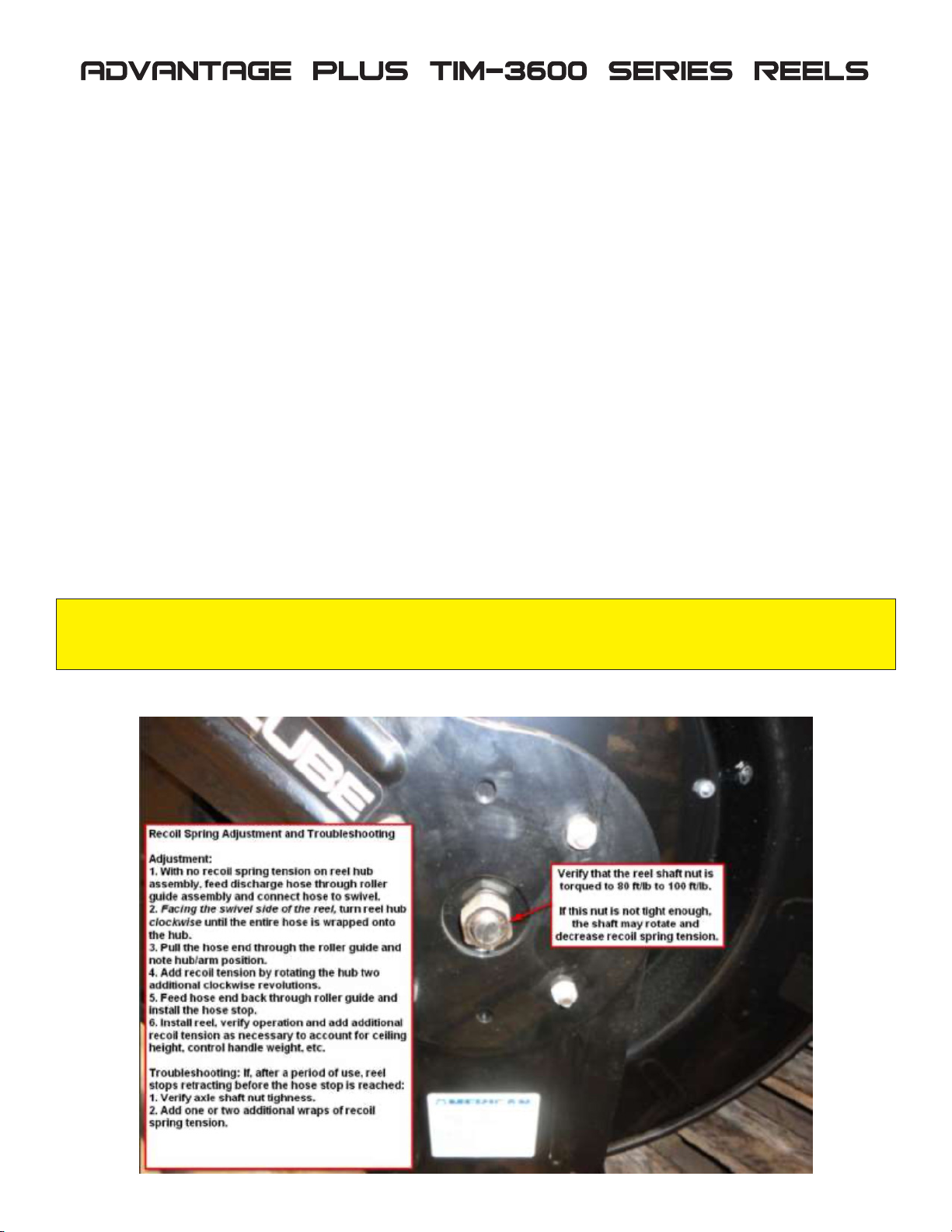
Adjustment of Spring Tension
1 Pull out approximately 6 ft or 2 m of hose and allow the drum to latch.
2 Remove hose stopper from hose, and feed hose back through guide.
3 Wrap the pulled hose one time around the drum to increase tension or un-wrap hose one time from
drum to decrease tension.
4 Re-insert hose through guide, and install stopper onto hose end.
5 Unlatch the Drum and check tension. Pull hose from reel, and adjust stopper position if necessary.
Replacement of Swivel Seal (TIM-3600-34 only)
1 Turn off and disconnect supply line from swivel inlet.
2 Remove swivel assembly from reel axle.
3 Remove circlip from swivel, and take apart.
Note: You may want to remove swivel from reel hose end, but this is not necessary unless a new swivel is
being installed.
4 Replace the seals and reassemble swivel.
5 Use Teon type or thread sealant on swivel thread tting, reconnect the swivel thread tting with axle.
6 Re-connect inlet supply line.
Replacement of Hose
1 Turn off supply to reel.
2 Pull out all the old hose and lock the reel in this position.
Caution: Make sure reel drum is securely locked and cannot rotate back.
3 Remove two hose clamps from hose.
4 Carefully disconnect hose from swivel joint on side of reel, or male tting in axle center and remove
old hose.
5 Feed new hose through guide and opening in drum, and connect to swivel. Re-install two hose
clamps, on inside and outside of drum ange. Install stopper on other end of hose in the same
position as before.
6 Carefully release the drum latch, and slowly allow the hose to wind onto the reel.
Note: Final spring adjustment is accomplished by adding or removing wraps of hose around the drum.
(Details see spring tension adjustment).
Spring Canister Warning
If the rewind spring fails for any reason: For safety reasons, the rewind spring is not repairable.
3
Advantage TIM-3600 Series Reel, Manual, June2020

4
Advantage TIM-3600 Series Reel, Manual, June2020

TIM-3600 Series Parts List
NOTE: Position numbers not listed below are not available for purchase as individual piece parts.
5
Advantage TIM-3600 Series Reel, Manual, June2020
# Qty. Description Part Number (P/N)
01 1 Reel Base TIM-3600-1A
02 1 Reel Arm TIM-3600-2
03 1 Guide Plate TIM-3600-3
04-07 1Roller Assembly
Roller Assembly includes #4 through #7.
Non-DEF reels, order: TIM-3600-4
DEF reels, order: TBD
17-23 1Ratchet Assembly Ratchet Assembly includes #17 through #23, order: TIM-3600-14
22 1 Spring Dog Spring #22 is included in the Ratchet Assembly above but is also sold individually, order: TIM-3600-22
25 1 Locking Ring TIM-3600-16
26 1 Hub Bearing TIM-3600-17
30 3 Nut TIM-3600-21
31-37 1Rewind Spring Assy.
Reel Rewind Spring Assembly includes #31 through #17, order:
TIM-3616-50 TIM-3600-23
TIM-3616-65 TIM-3600-24
TIM-3618-50 TIM-3600-25
TIM-3618-65 TIM-3600-26
TIM-3628-25 TIM-3600-29
TIM-3628-50 TIM-3600-27
TIM-3636-50 TIM-3600-30
TIM-3636-65 TIM-3600-31
TIM-DEF-52H33S Not Available
40-44 1Swivel Assembly
Reel Swivel Assembly includes #40 through #44, order:
TIM-3616-xx TIM-3600-32
TIM-3618-xx TIM-3600-34 NOTE: O-ring swivel seal kit is available, order: TIM-OILSWIV-KIT
TIM-3628-xx TIM-3600-34 NOTE: O-ring swivel seal kit is available, order: TIM-OILSWIV-KIT
TIM-3636-xx TIM-3600-36
TIM-DEF-52HxxS Not Available
47 1
Hose, Delivery
NOTE: Connection
hose is not shown in
the illustration
Reel Delivery Hose, order: Connection Hose, order:
TIM-3616-50 TIM-4216-50 TIM-4216-2N
TIM-3616-65 TIM-4216-65 TIM-4216-2N
TIM-3618-50 TIM-4208-50S TIM-4218-2N
TIM-3618-65 TIM-4208-65S TIM-4218-2N
TIM-3628-25 TIM-4418-25S TIM-4418-2NS
TIM-3628-50 TIM-4418-50S TIM-4418-2NS
TIM-3628-65 TIM-4418-65S TIM-4418-2NS
TIM-3636-50 TIM-4506-50S TIM-4516-2N
TIM-3636-65 TIM-4506-65S TIM-4516-2N
TIM-DEF-52H33S DEF-33FHS DEF-31 (per foot)
48-50 1 Hose Stop Assembly
3/8” Air/Grease hose, order: TIM-131-3
1/2” Air/Oil hose, order: TIM-131-4
DEF hose, order: TIM-430
51 2 Hose Clamp Non-DEF reels, order: TIM-HOSE-CLMP
DEF Reels, order: TIM-CLAMP-18
53 2 Nut TIM-3600-42
N/A 1 Hose Protection Spring Non-DEF reels, order: TIM-238-1
DEF Reels, order: TIM-398-1
For pricing and ordering information, please call 410-252-9300 and press 2 or email
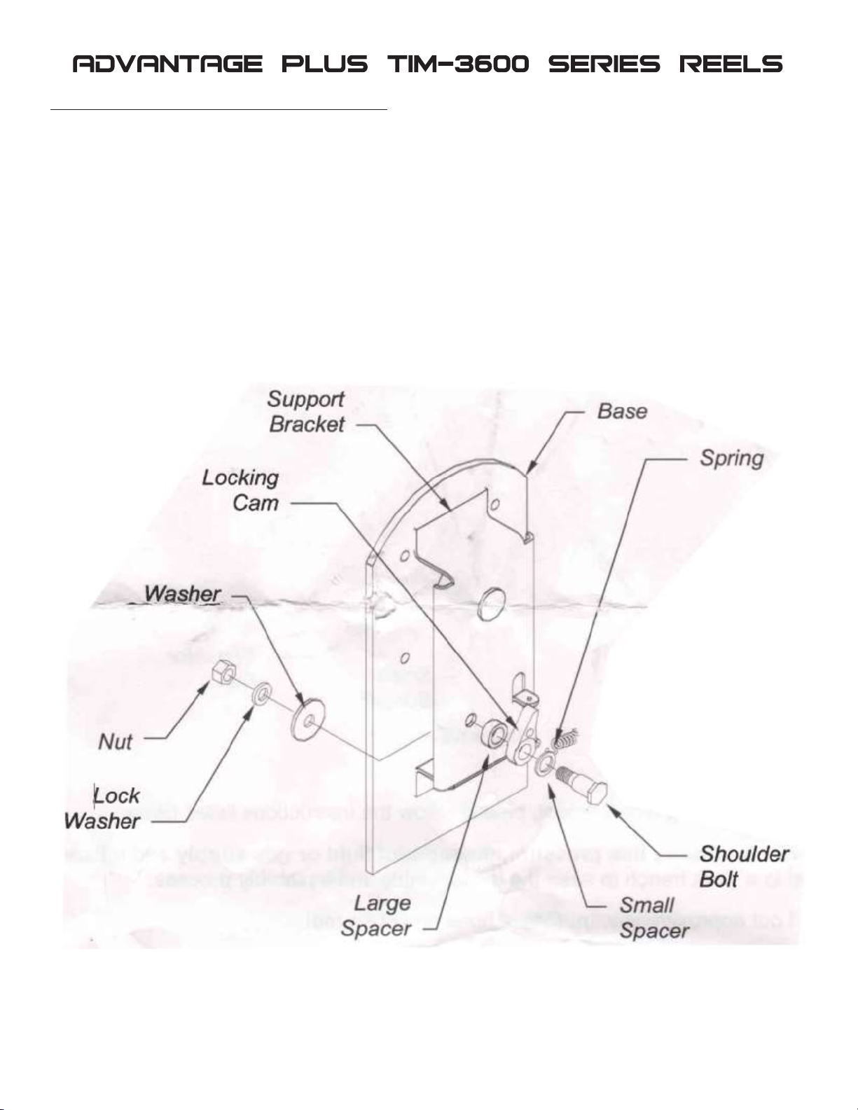
TIM-3600-14 Ratchet Assembly Replacement
Replacement procedure:
1. Remove uid pressure.
2. Pull 3’ of hose out of reel.
3. Remove control handle, hose stop, etc.
4. Relieve all recoil spring tension by slowly retracting the hose into the reel.
5. Remove swivel retaining ring and spacer.
6. Slide drum off axle.
7. Replace old parts with new TIM-3600-14 kit parts (cam, spring, bolt, etc.).
8. Reassemble.
9. Tension reel by turning the drum three complete turns.
10. Latch drum.
11. Reassemble hose stop, etc.
6
Advantage TIM-3600 Series Reel, Manual, June2020

Mounting Hole Dimensions
L = 3-1/2”; M = 7-1/2”
Optional Side-In Mounting Bracket
• 12.75” length, holes center to center = 6.75”;
• 10.5” width, holes center to center = 8-7/8”
7
Advantage TIM-3600 Series Reel, Manual, June2020
A B C D E Mount
L-M
8-7/16" 21-1/2" 20-5/8" 5-3/4" 9" 3-1/2" x 7-1/2"
B
C
A
E
D
M
L
14' maximum mounting height
TIM-3600-50
12-3/4” L x 10-1/2” W slide-in mounting bracket simplifies reel mounting by allowing for one man installations.
Easily mounts to Uni-Strut® using Uni-Strut® hardware (not included). Can also be mounted by drilling
and fastening to an I-Beam or H-Beam (fastening hardware not included). 1/8" steel construction.
Base replacement procedure:
1. Note: Can be done on scissors lift in the ceiling.
2. Remove system air pressure.
3. Remove control valve and hose stop.
4. Allow hose to retract completely.
5. Remove air line from swivel.
6. Remove 7/8” axle nut.
7. Pull hub off base.
8. Assemble stop dog assembly on new base.
9. Remove old base.
10. Using new base, reverse disassembly procedure to reassemble.
Rewind Spring Assembly Removal and Replacement.
1. Disconnect air and oil.
2. Remove gun and hose stop.
3. Allow hose to fully retract into reel. NOTE: Typically, the retraction is about four rotations past the
hose stop. The retraction unloads/releases the spring motor tension.
4. Remove swivel.
5. Remove axle snap ring and axle washer.
6. Remove reel hub (with delivery hose, rewind spring assembly, etc.) from the reel base. NOTE: Axle
stays on base.
7. Remove four nuts that protrude from the far side (side opposite the rewind spring canister) of the
hub. The four nuts screw onto studs protruding from the interior side of the rewind spring canister.
The four nuts attach the rewind spring canister to the reel hub.
WARNING: Exposure of the encapsulated/enclosed rewind spring could result in severe bodily injury. The
canister must remain sealed/complete/intact. Do not remove the nuts on the exterior face of the rewind
spring canister.
8. Remove the complete/intact rewind spring canister and replace the rewind spring canister.
9. Reassemble the reel and adjust rewind spring tension as appropriate.
8
Advantage TIM-3600 Series Reel, Manual, June2020
Table of contents


