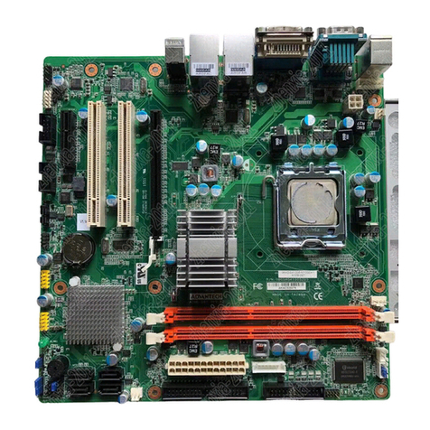
v AIMB-252 User Manual
Contents
Chapter 1 Production Introduction......................1
1.1 Before You Proceed..................................................................................2
1.2 Motherboard Overview..............................................................................2
1.2.1 Placement Direction......................................................................2
1.2.2 Screw Holes..................................................................................3
1.3 Motherboard Layout..................................................................................4
Figure 1.1 Motherboard Layout ...................................................4
1.4 Specifications............................................................................................5
1.5 Board Diagram..........................................................................................7
1.6 Ordering Information.................................................................................8
1.7 Riser Card.................................................................................................8
1.8 Bracket View .............................................................................................8
1.9 Accessories...............................................................................................8
1.10 Layout Content List...................................................................................9
Table 1.1: Slots............................................................................9
Table 1.2: Rear Panel Connector................................................9
Table 1.3: Internal Connector......................................................9
Table 1.4: CMOS1.....................................................................10
Table 1.5: ATX/AT mode selector(JPSON1).............................10
Table 1.6: COM1 RS-232/422/485 mode selector (JSETCOM1)..
11
1.11 Central Processing Unit (CPU) (for AIMB-252(915GME) only)...............11
1.11.1 Installing the CPU.......................................................................12
1.11.2 Installing the CPU Heatsink and Fan..........................................14
1.11.3 Uninstalling the CPU Heatsink and Fan......................................16
1.12 System Memory......................................................................................16
1.12.1 DIMM Sockets Location..............................................................16
1.12.2 Memory Configurations...............................................................17
1.12.3 Installing a DDR2 DIMM .............................................................18
1.12.4 Removing a DDR2 DIMM ...........................................................19
1.13 Expansion Slots ......................................................................................19
1.13.1 Installing an Expansion Card ......................................................19
1.13.2 Configuring an Expansion Card..................................................19
1.13.3 Standard Interrupt Assignments .................................................20
Table 1.7: Standard Interrupt Assignments...............................20
1.13.4 PCI Slots.....................................................................................20
1.14 Connectors..............................................................................................21
1.14.1 Rear Panel Connectors...............................................................21
Table 1.8: Rear Panel Connectors............................................21
Table 1.9: LEDs.........................................................................21
1.14.2 CPU Fan Connector (CPUFAN1) ...............................................22
1.14.3 System Fan Connector (SYSFAN1) ...........................................23
1.14.4 Serial Port Connector 23 (COM23).............................................24
1.14.5 Serial Port Connector 45 (COM45).............................................24
1.14.6 Front Headphone Connector (FPAUD1).....................................25
1.14.7 Front Panel Connector (JFP1/JFP2/JFP3) .................................26
1.14.8 ATX soft power switch (JFP1 / PWR_SW) .................................26
1.14.9 Reset (JFP1 / RESET)................................................................26
1.14.10HDD LED (JFP2 / HDDLED).......................................................26
1.14.11External speaker (JFP2 / SPEAKER) .........................................26
1.14.12Power LED and keyboard lock connector (JFP3 / PWR_LED&KEY
LOCK).........................................................................................27
Table 1.10:ATX power supply LED status (No support for AT pow-
er).............................................................................27
