manuals.online logo
Brands
  1. Home
  2. •
  3. Brands
  4. •
  5. Advantech
  6. •
  7. Motherboard
  8. •
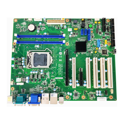
  9. Advantech PCE-5129 Installation and operation manual

Advantech PCE-5129 Installation and operation manual

This manual suits for next models

2

Other Advantech Motherboard manuals

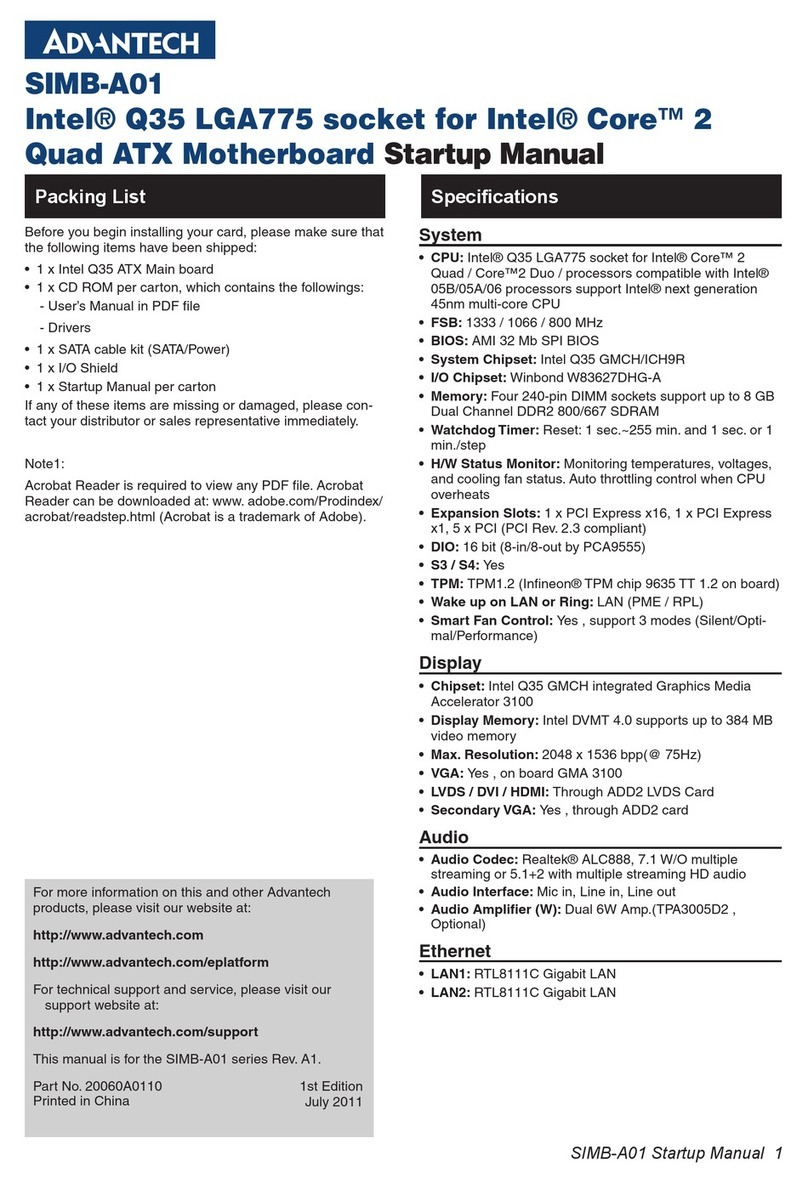
Advantech PCM-9590 User manual

Advantech

Advantech PCM-9590 User manual

Advantech PCA-6743 Installation and operation manual

Advantech

Advantech PCA-6743 Installation and operation manual

Advantech AIMB-784 User manual

Advantech

Advantech AIMB-784 User manual

Advantech AIMB-781 User manual

Advantech

Advantech AIMB-781 User manual

Advantech AIMB-U233 User manual

Advantech

Advantech AIMB-U233 User manual

Advantech AIMB-706 User manual

Advantech

Advantech AIMB-706 User manual

Advantech MIO-2270 User manual

Advantech

Advantech MIO-2270 User manual

Advantech PCM-3365 User manual

Advantech

Advantech PCM-3365 User manual

Advantech PCE-5128 User manual

Advantech

Advantech PCE-5128 User manual

Advantech AIMB-764 Installation and operation manual

Advantech

Advantech AIMB-764 Installation and operation manual

Advantech SMB-2501 User manual

Advantech

Advantech SMB-2501 User manual

Advantech ASMB-786 User guide

Advantech

Advantech ASMB-786 User guide

Advantech PCM-4390 Installation and operation manual

Advantech

Advantech PCM-4390 Installation and operation manual

Advantech AIMB-506 User manual

Advantech

Advantech AIMB-506 User manual

Advantech SIMB-U01 User manual

Advantech

Advantech SIMB-U01 User manual

Advantech PCM-9570 Installation and operation manual

Advantech

Advantech PCM-9570 Installation and operation manual

Advantech AIMB-582 User manual

Advantech

Advantech AIMB-582 User manual

Advantech ROM-3420CD-MDA1E User manual

Advantech

Advantech ROM-3420CD-MDA1E User manual

Advantech AIMB-581 User manual

Advantech

Advantech AIMB-581 User manual

Advantech PCE-5120 User manual

Advantech

Advantech PCE-5120 User manual

Advantech SOM-AB5810 User manual

Advantech

Advantech SOM-AB5810 User manual

Advantech AIMB-203 User manual

Advantech

Advantech AIMB-203 User manual

Advantech AIMB-213 Installation and operation manual

Advantech

Advantech AIMB-213 Installation and operation manual

Advantech AIMB-225 User manual

Advantech

Advantech AIMB-225 User manual

Popular Motherboard manuals by other brands

Gigabyte MNJ190I-FH user manual

Gigabyte

Gigabyte MNJ190I-FH user manual

Biostar HI-FI-Z87X-3D Setup manual

Biostar

Biostar HI-FI-Z87X-3D Setup manual

Atmel SAM9753PIA-DK user guide

Atmel

Atmel SAM9753PIA-DK user guide

Coapt GEN2 Handbook

Coapt

Coapt GEN2 Handbook

Supero SUPER P4DL6 user manual

Supero

Supero SUPER P4DL6 user manual

Cypress CY3210-PSoCEVAL1 quick start guide

Cypress

Cypress CY3210-PSoCEVAL1 quick start guide

ASROCK B660M-HDV manual

ASROCK

ASROCK B660M-HDV manual

Fujitsu D2831 Short description

Fujitsu

Fujitsu D2831 Short description

Industrial Computers ADE-6050 user manual

Industrial Computers

Industrial Computers ADE-6050 user manual

Asus TUF Z270 MARK 2 manual

Asus

Asus TUF Z270 MARK 2 manual

DFI NB71-BC user manual

DFI

DFI NB71-BC user manual

ASROCK H61 Pro BTC user manual

ASROCK

ASROCK H61 Pro BTC user manual

Norco POS-7893 user manual

Norco

Norco POS-7893 user manual

Intel DG965MS specification

Intel

Intel DG965MS specification

Asus B85M-VIEW PAKER user manual

Asus

Asus B85M-VIEW PAKER user manual

Asus P5G41T-M LX V2 user manual

Asus

Asus P5G41T-M LX V2 user manual

Gigabyte GA-K8VT800-RH user manual

Gigabyte

Gigabyte GA-K8VT800-RH user manual

Gigabyte Z790M AORUS ELITE user manual

Gigabyte

Gigabyte Z790M AORUS ELITE user manual

manuals.online logo
manuals.online logoBrands
  • About & Mission
  • Contact us
  • Privacy Policy
  • Terms and Conditions

Copyright 2025 Manuals.Online. All Rights Reserved.

PCE-7129/5129/5029 Startup Manual 1
Before you begin installing your card, please make sure that
the following items have been shipped:
1. 1 x PCE-7129/5129/5029 PICMG 1.3 Single Host Board
2. 1 x PCE-7129/5129/5029 Startup Manual
3. 1 x CD with utility
4. 1 x Serial ATA HDD data cables
5. 1 x Serial ATA HDD power cables
6. 1 x COM port cable kit
7. 1 x 2-port USB cable kit
8. 1 x Keyboard and mouse Y cable
9. 1 x Jumper package
10. 1 x Warranty card
If any of these items are missing or damaged, please con-
tact your distributor or sales representative immediately.
Note 1: For detailed contents of PCE-7129/5129/5029,
please refer to the user manual in the enclosed
CD-ROM (in PDF format).
Note 2: Acrobat Reader is required to view any PDF
le. Acrobat Reader can be downloaded at: get.
adobe.com/reader (Acrobat is a trademark of
Adobe)
PCE-7129/5129/5029 LGA1151 Intel®CoreTM i7/i5/i3/
Pentium®/Xeon®(PCE-7129) PICMG 1.3 Single Host
Board with (ECC) DDR4/M.2 (2280)/Dual GbE LAN
Startup Manual
General
• LGA1151 6th and 7th Intel®Core™ i7/i5/i3/Pentium®/
Xeon®
• BIOS: AMI 128 Mb SPI BIOS
• Chipset:
- PCE-7129: Intel® C236
- PCE-5129: Intel® Q170
- PCE-5029: Intel® H110
• System memory:
- PCE-7129: Supports dual channel DDR4 1866/2133
16GB per DIMM with ECC; Max. capacity is up to 32GB
- PCE-5129/5029: Supports dual channel DDR4
1866/2133 16GB per DIMM without ECC; Max. capacity
is up to 32GB
Note1: Please select Intel® ECC supported processor to
enable ECC function.
Note2: Supports DDR4 1024M x 8 memory technology.
• SATA Ports:
- PCE-7129/5129 supports 5 SATA3.0 ports with SW Raid
0,1,5,10.
- PCE-5029 supports 4 SATA3.0 ports without Raid
function.
• M.2 Ports: PCE-7129/5129 supports M.2 2280 type M
module and compatible to both SATA3.0 and PCI Express
3.0 standard.
• Serial ports: Two RS-232 with pin headers
Note: PCE-5029VG SKU feature 1*pin header and 1* rear
COM port.
• Keyboard/mouse connector: Supports one standard
PS/2 keyboard and mouse connector and one external
6-pin header.
• Watchdog timer: 255 level timer intervals
• USB 2.0: PCE-7129/5129/5029: 7 * USB 2.0 (Pin-
header*2+USB Type-A*1+, 4 on backplane)
• USB 3.0:
- PCE-7129/5129: 5 * USB 2.0 (Pin-header*4+Rear USB
3.0 * 1)
- PCE-5029: 3 * USB 2.0 (Pin-header*2+Rear USB 3.0
* 1)
• GPIO: One programmable 8-bit GPIO pin-header
VGA Interface
• Chipset: Intel®HD Graphics
• Shared system memory is subject to OS
Ethernet Interface
• Chipset supports:
- LAN 1: I219LM(PCE-7129/5129); I219V(PCE-5029)
- LAN 2: I210AT(PCE-7129); I210AT (PCE-5129/5029)
• Connection: 2 on-board RJ-45 connectors with LED indica-
tors
Specications
Packing List
For more information on this and other Advantech
products, please visit our website at:
http://www.advantech.com
For technical support and service, please visit our
support website at:
http://www.advantech.tw/support
This manual is for the PCE-7129/5129/5029 Series
Rev. A3.
Part No. 2001512912
Printed in China
3rd Edition
October 2022
2 PCE-7129/5129/5029 Startup Manual
Mechanical and Environmental
• Dimensions: (L x W): 338 x 122 mm
• Power supply voltage: +12 V, +5 V, +3.3 V, +5 V
SB
• Power requirements:
- CPU: Processor: Intel
®
Core™ i7-6700
- Memory: 2 DDR4 2133 8 GB DIMMs
- Voltage: +12 V, +5 V, +3.3 V, +5 V
SB
, 12 V,-5 V
- Current: 2.64 A, 1.23 A, 0.19 A, 0.09 A, 0.06 A, 0 A
- Operating temperature: 0 ~ 60 °C (depending on CPU)
• Weight: 0.5 kg (weight of board)
The board has a number of jumpers that allow you to con-
gure your system to suit your application. The table below
lists the function of each of the jumpers and connectors.
Connectors
Label Function
USB3_1 USB3 port1
LAN1 Intel® I219LM(PCE-7129/5129); Intel®
I219V(PCE-5029)
LAN2 Intel® I210AT(PCE-7129); Intel® I210AT
(PCE-5129/5029)
VGA1 VGA connector
KBMS1 External PS/2 keyboard and mouse
connector
KBMS2 Internal PS/2 keyboard and mouse
connector
HDAUD1 Advantech HD audio module expansion
pin-header
LPC1 LPC module expansion pin-header
Sysfan1 4 PIN fan power connector for support-
ing PWM or DC fan
LANLED1 LANLED
USB11 USB port 10
USB45 USB port 4, 5
USB3_45 USB3 port 4, 5
USB3_23 USB3 port 2,3
COM1 RS-232 (9-pin Box Header)
COM2 RS-232 (9-pin Box Header)
LPT1 Parallel port
SATA0 /
NGFF1 SATA port 0 or PCIex4
SATA 1~5 SATA Port 1 ~ 5
SPI_CN1 CMOS ash jig pin-header
SPI1 CMOS ROM
DP1 Display port pin-header 1
Jumpers and Connectors
DP2 Display port pin-header 1
JCMOS1 Clear CMOS
JME1 Clear ME
JFP1 + JFP2 Power Switch / Reset connector / Exter-
nal speaker / SATA HDD LED connector
JFP3
(Keyboard
Lock and
Power LED)
Power LED
Suspend: Fast ash (ATX/AT)
System On: ON (ATX/AT)
System O󰀨: OFF (ATX/AT)
CPUFAN1 CPU FAN Power connector
SYSFAN1
System FAN Power Connector for 1
system FAN
JCASE1 Case Open pin-header
JCASEOP_
SW1
Case Open switch for always open or
close
BAT1 Button battery socket
BAT2 External battery connector
GPIO1 GPIO pin header (SMD pitch-2.0 mm)
DIMMA1 Memory connector channel A
DIMMB1 Memory connector channel B
Jumpers
Label Function
JCMOS1 CMOS clear
JME1 Clear ME data
JWDT1 Watchdog timer output selection
JOBS1 SIO Monitor Alarm
JCMOS1/JME1: Clear CMOS/ME data
Closed Pins Result
1-2 Keep CMOS/ME data (Default)
2-3 Clear CMOS/ME data
123
Specications(Cont.)
JumpersandConnectors(Cont.)
PCE-7129/5129/5029 Startup Manual 3
H/Wmonitoralarm(JOBS1) 
Function Jumper Setting
Closed Enable OBS alarm (Default)
Open Disable OBS alarm
JWDT1: Watchdog timer output option
Closed Pins Result
1-2 Reserved
2-3 System reset (Default)
The drivers for PCE-7129/5129/5029 are located on the
software installation CD. Please click through the folder and
follow the screen instructions to install them.
1 2 3
Board Layout
Software Installation
Caution! The computer is supplied with a battery-powered
real-time clock circuit. There is a danger of
explosion if the battery is incorrectly replaced.
Replace only with the same or equivalent type
recommended by the manufacturer. Discard
used batteries according to the manufacturer’s
instructions.
This device complies with the requirements in Part 15 of
the FCC rules. Operation is subject to the following two
conditions:
1. This device may not cause harmful interference;
2. This device must accept any interference received,
including interference that may cause undesired opera-
tion.
JumpersandConnectors(Cont.)
Figure 1: Board Layout: Jumper and Connector Locations
Note: *PCE-5029VG SKU features one rear COM port and one internal pin-header COM port.
*PCE-5029 supports 4 SATA ports (SATA0~4) and one internal USB 3.0 pin-header.
*PCE-5029 doesn’t feature NGFF(M.2).
*PCE-5029 supports 1 DP port.
USB11
USB45
USB3_45
USB3_23
USB3_1
LAN2
LAN1
LANLED1
VGA1
DP 1
DP 2
JIR1
JWDT1
JOBS1
SATA 1~5SPI1_CNDIMM A1 DIMM B1
JFP1~3CPUFAN1
JCASEOP_SW1
JCASE1
BAT2
CPU1 NGFF1
SATA0
COM
OM1
C
PCH1 GPIO1 LPC1
HDAUDIO1
KBMS1
KBMS2
2
SYSFAN1
Declaration of Conformity
Closed Open