manuals.online logo
Brands
  1. Home
  2. •
  3. Brands
  4. •
  5. Advantech
  6. •
  7. PCI Card
  8. •
  9. Advantech PCI-1601 User manual

Advantech PCI-1601 User manual

2nd Edition
Printed in Taiwan July 2001
Copyright Notice
This documentation and the software included with this product are
copyrighted 2001 by Advantech Co., Ltd. All rights are reserved.
Advantech Co., Ltd. reserves the right to make improvements to the
products described in this manual at any time without notice.
No part of this manual or software may be reproduced, copied,
translated or transmitted, in any form or by any means without the
prior written permission of Advantech Co., Ltd. Information provided
in this manual is intended to be accurate and reliable. However,
Advantech Co., Ltd. assumes no responsibility for its use, nor for any
infringements of rights of third parties which may result from its use.
Acknowledgments
PC-LabCard is a trademark of Advantech Co., Ltd. IBM, PC and
PC/XT/AT are trademarks of International Business Machines
Corporation. MS-DOS, MASM, QuickBASIC, Microsoft C and MS-
PASCAL are trademarks of Microsoft Corporation. Intel is a trademark
of Intel Corporation. Turbo C and Turbo PASCAL are trademarks of
Borland International.
Contents
Chapter 1: Introduction ................................................ 1
Description ............................................................................. 2
Features .................................................................................. 2
Specifications ......................................................................... 3
Ordering Information .......................................................... 5
Chapter 2: Hardware Configuration ............................. 7
Initial Inspection.................................................................... 8
Jumper and Switch Locations ............................................. 9
Jumper settings ................................................................... 14
How to set jumpers............................................................ 14
Default Settings ................................................................. 14
Card installation.................................................................. 15
RS-422/485 selection (for PCI-1601/1602/1612) .......... 16
Enable mode selection ...................................................... 16
Terminator resistor setup (for PCI-1601/1602/1612)..... 16
Chapter 3: Driver Setup & Installation ....................... 17
Overview .............................................................................. 18
For Windows 95/98 Driver Setup..................................... 18
For Windows NT Driver Setup ......................................... 18
Windows 95/98 Driver Setup............................................. 19
Steps for Windows 95/98 Driver Setup ........................... 19
Reboot your system after Win95/98 driver Setup .......... 22
PCI UARTs Device Driver Installation ...................................................... 22
PCI Bridge Device Driver Installation........................................................ 26
Verify your Win95/98 Driver Setup................................. 27
Configure PCI ICOM serial devices on Windows 95/9831
Configuring PCI UARTs Device ................................................................. 33
Configuring PCI Bridge Device ................................................................... 34
Configuring ports ........................................................................................ 34
Remove PCI ICOM series device..................................... 38
Steps for Complete Win98/98 Driver Uninstall.............. 42
Windows NT Driver Setup................................................. 43
Steps for Windows NT Driver Setup................................ 43
Start the Device Function in Windows NT...................... 47
Verify your NT driver Setup............................................. 48
Verify your NT Driver Function ...................................... 49
Stop the Device Function in Windows NT...................... 50
Chapter 4: ICOM Tools ................................................. 51
Introduction ......................................................................... 52
Installation ........................................................................... 52
User Interface of ICOM Tools.......................................... 52
Using the ICOM Tools utility ............................................ 56
Port Selection ..................................................................... 56
4.3.2 Configure the Port .................................................. 58
Run the test................................................................................................. 59
Stop the test................................................................................................ 60
Close Port ........................................................................... 61
Exit the ICOM Tools utility............................................... 61
Messages on the Status Bar and Message Logo area ... 61
Status Bar messages .......................................................... 61
Message Logo messages .................................................. 61
Chapter 5: Pin Assignment & Wiring .......................... 63
Pin assignments ................................................................... 64
PCI-1601/1602 .................................................................. 64
RS-422 signal wiring ........................................................ 64
RS-485................................................................................ 64
PCI-1610/1612 .................................................................. 65
PCI-1620 ............................................................................ 66
Wiring ................................................................................... 68
RS-232 signal wiring ........................................................ 68
Terminal or PC (DTE) connections........................................................... 68
Modem connections ................................................................................... 69
Terminal without handshake....................................................................... 69
RS-422 signal wiring ........................................................ 70
Terminator Resistors setup ............................................... 70
RS-485 signal wiring ........................................................ 71
Termination resistor setup................................................. 72
Chapter 1 Introduction 1
1
Introduction
CHAPTER
2PCI Comm Card Series User's Manual
Description
The PCI Local Bus is a high-performance bus that provides a proces-
sor-independent data path between the CPU and high-speed peripher-
als. PCI is a robust interconnect mechanism designed specifically to
accommodate multiple high performance peripherals for series
communication, SCSI, LAN, etc.
Advantech serial communication cards leverages the " Plug and Play
" capability defined in the PCI 2.1 bus specification. The board
requires only one PCI slot within the personal computer and provides
independent serial channels. All channels are addressed in a continu-
ous 32 byte I/O block for simplified software access. And, all channels
may also share one PCI interrupt. An interrupt status register is
available for determining the interrupt source.
The Advantech PCI communication card comes standard with
16PCI954 UARTs containing 128 byte FIFOs which are available as
an option. These upgraded FIFOs greatly reduce CPU overhead and
are an ideal choice for heavy multitasking environments.
16PCI954
The 16PCI954 is a high performance Quad UART with an on-chip PCI
interface. Targeted at PCI-based serial and parallel expansion cards,
PCI-architecture computer systems and embedded applications, the
16PCI954 integrates a PCI bus interface together with four of 16C950
high performance UARTs, a bi-directional parallel port and a local
bus bridge function. This single-chip solution replaces five or more
integrated circuits used in today products, giving performance, cost
and size advantages for new designs.
Features
•PCI Specification 2.1 compliant
•Speeds up to 921.6 Kbps
•16C954/950 UARTs with 128-byte standard
•Standard Industrial Board size
•I/O address automatically assigned by PCI Plug-and-Play
Chapter 1 Introduction 3
•OS supported: Windows NT, Windows 95, Windows 98
•Optional surge protection
•Optionalisolationprotection for RS-422/485
•Interrupt status register for increased performance
•Space reserved for termination resistors
•AutomaticRS-485data flow control
Specifications
•BusInterface: PCI bus specification 2.1 compliant
•IRQ: all ports use the same IRQ assigned by PCI Plug-and-Play
•Databits:5,6,7,8
•Stopbits:1,1.5,2
•Parity: none, even, odd
•Communicationcontroller:
16PCI954+16C954forPCI-1620A/B
16PCI954 for PCI-1610A/B, PCI-1612A/B
16PCI954 for PCI-1601A/B, 1602A/B
•Speed (bps) : 50 ~ 921.6 K
•Data signals:
TxD, RxD,RTS, CTS,DTR, DSR,DCD, GND(for RS-232)
RI(forPCI-1610)
TxD,RxD, RTS,CTS(for RS-422)
4PCI Comm Card Series User's Manual
Typical Max
PCI-1620 120 mA (+12 V) 150 mA (+12 V)
180 mA (+5 V) 220 mA (+5 V)
PCI-1610 60 mA (+12 V) 80 mA (+12 V)
150 mA (+5 V) 180 mA (+5 V)
PCI-1601 220 mA 270 mA
PCI-1602 250 mA 300 mA

PCI-1612 60 mA (+12 V) 80 mA (+12 V)
270 mA (+5 V) 340 mA (+5 V)
•Powerrequirement:
• Dimensions: 185 mm x 100 mm (for PCI-1612/1620)
123 mm x 92 mm (for PCI-1601/1602/1610)
•Operating temperature: 0o~ 65oC (referring to IEC
68-2-1, 2)
•Operating Humidity: 5 ~ 95% Relative Humidity, non-condensing
(referring to IEC 68-2-1, 2)
•Operating Humidity: 5 ~ 95% Relative Humidity, non-condensing
(referring to IEC 68-2-3)
•Storage Temperature: -25 ~ 85oC
Chapter 1 Introduction 5
Ordering Information
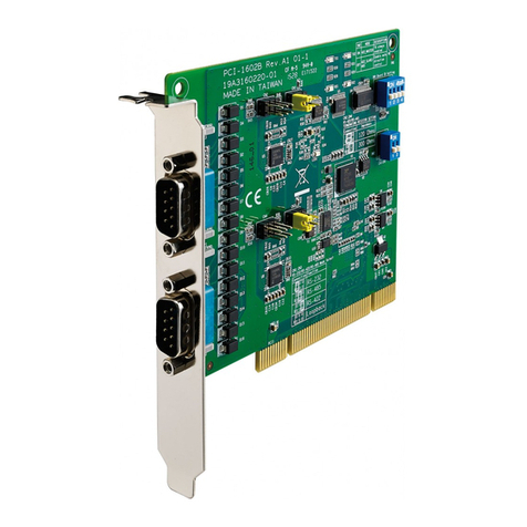
PCI-1601A: 2-port RS-422/485 PCI Comm Card
PCI-1601B: 2-port RS-422/485 PCI Comm Card, w/surge protection
PCI-1602A: 2-port RS-422/485 PCI Comm Card. w/ isolation protection
PCI-1602B: 2-port RS-422/485 PCI Comm Card, w/isolation and
surge protection
PCI-1620A: 8-port RS-232 PCI Comm Card
PCI-1620B: 8-port RS-232 PCI Comm Card, w/surge protection
PCI-1610A: 4-port RS-232 PCI Comm Card
PCI-1610B: 4-port RS-232 PCI Comm Card, w/surge protection
PCI-1612A: 4-port RS-232/422/485 PCI Comm Card
PCI-1612B: 4-port RS-232/422/485 PCI Comm Card, w/surge protection
Series PCI-1601 PCI-1602 PCI-1610 PCI-1612 PCI-1620
A B A B A B A B A B
No. of Port 2 2 2 2 4 4 4 4 8 8
Interface RS-422/485 RS-422/485 RS-232 RS-232/422/
485 RS-232
Surge
Protection -2500
VDC -2500
VDC -3000
VDC N/A 2500
VDC -3000
VDC
Isolation
Protection - - 3000
VDC
3000
VDC ------
6PCI Comm Card Series User's Manual
Chapter 2 Hardware Configuration
7
2
Hardware
Configuration
CHAPTER
8PCI Comm Card Series User's Manual
Initial Inspection
You should find the following items inside the shipping package (in
addition to this manual):
•PCI communication interface card
•Advantech Automation Software
•PCI communication card user's manual
We carefully inspected the PCI communication card series mechani-
cally and electrically before we shipped it. It should be free of marks
and scratches and in perfect working order on receipt.
As you unpack the PCI communication card series, check it for signs
of shipping damage (damaged box, scratches, dents, etc.). If it is
damaged or it fails to meet specifications, notify our service depart-
ment or your local sales representative immediately. Also notify the
carrier. Retain the shipping carton and packing material for inspec-
tion by the carrier. After inspection we will make arrangements to
repair or replace the unit.
When you handle the PCI communication card series, remove it from
its protective packaging by grasping the rear metal panel. Keep the
anti-vibration packing. Whenever you remove the card from the PC,
store it in this package for protection.
Warning! Discharge your body’s static electric charge by
touching the back of the grounded chassis of the
system unit (metal) before handling the board.You
should avoid contact with materials that hold a static
charge such as plastic, vinyl and styrofoam. Handle
the board only by its edges to avoid static damage to
its integrated circuits.Avoid touching the exposed
circuit connectors.We also recommend that you use
a grounded wrist strap and place the card on a static
dissipative mat whenever you work with it.
Chapter 2 Hardware Configuration
9
Jumper and Switch Locations
PCI-1601 Silk ScreenPCI-1601 Silk Screen
PCI-1601 Silk Screen
10 PCI Comm Card Series User's Manual
PCI-1602 Silk ScreenPCI-1602 Silk Screen
PCI-1602 Silk Screen
Chapter 2 Hardware Configuration
11
PCI-1610 Silk ScreenPCI-1610 Silk Screen
PCI-1610 Silk Screen
12 PCI Comm Card Series User's Manual
PCI-1612 Silk ScreenPCI-1612 Silk Screen
PCI-1612 Silk Screen
Chapter 2 Hardware Configuration
13
PCI-1620 Silk ScreenPCI-1620 Silk Screen
PCI-1620 Silk Screen
14 PCI Comm Card Series User's Manual
PCI-1601 PCI-1602 PCI-1612
RS-422/485 Mode RS-422 RS-422 RS-422
Enable Mode Auto Auto Auto
Jumper settings
This section tells how to set the jumpers to configure your card. It
gives the card default configuration and your options for each jumper.
How to set jumpers
You configure your card to match the needs of your application by
setting jumpers. A jumper is the simplest kind of electric switch. It
consists of two metal pins and a small metal clip (often protected by a
plastic cover) that slides over the pins to connect them. To “close” a
jumper you connect the pins with the clip. To “open” a jumper you
remove the clip. Sometimes a jumper will have three pins, labeled 1, 2
and 3. In this case you would connect either pins 1 and 2 or 2 and 3.
You may find pair of needle-nose pliers useful for setting the jumpers.
If you have any doubts about the best hardware configuration for your
application, contact your local distributor or sales representative
before you make any changes.
Default Settings
The board is shipped with default settings. If you need to change
these settings, however, see the following sections. Otherwise, you can
simply install the card.
OpenOpen
OpenOpen
Open ClosedClosed
ClosedClosed
Closed Closed 2-3Closed 2-3
Closed 2-3Closed 2-3
Closed 2-3
Chapter 2 Hardware Configuration
15
Card installation
Warning! Turn off your PC’s power supply whenever you install
or remove the PCI communication card or its cables.
Static electricity can easily damage computer
equipment.Groundyourself by touching the chassis
ofthecomputer (metal) before you touch anyboards.
See the static warning on page 6
1. Turn off the computer. Turn the power off to any peripheral devices
(such as printers and monitors).
2. Disconnect the power cord and any other cables from the back of
the computer. Turn the PC if necessary to gain access to the
cables.
3. Remove the PC’s cover (refer to your user’s guide if necessary).
4. Locate the expansion slots or passive backplane (at the rear of the
PC) and choose any unused slot.
5. Remove the screw that secures the expansion slot cover to the PC
(save the screw to secure the interface card retaining bracket). Re
move the anti-vibration card clamp if supplied.
6. Carefully grasp the upper edge of the PCL-743/745 card. Align the
hole in the retaining bracket with the hole on top of the expansion
slot. Align the gold striped edge connector with the expansion slot
socket. Press the board firmly into the socket.
7. Replace the screw in the expansion slot retaining bracket. Replace
anti-vibration card holder.
8. Replace the PC’s cover. Connect the cables you removed in step 2.
Turn the computer power on.
The board is now installed in the computer. See Chapter 4 for infor-
mation on cabling.
16 PCI Comm Card Series User's Manual
RS-422/485 selection (for PCI-1601/1602/
1612)
You can set each port individually for either RS-422 (the default) or
RS-485 operation. The figure below shows the jumper settings. See
the "Jumper and Switch Locations" figure from page 7 to 11 for help
to locate the jumpers.
Enable mode selection
You set the Enable mode using two- or four- position DIP switches,
one for each port. If the switches are set to "AUTO", the driver auto-
matically senses the direction of the data flow and switches the
direction of transmission. No handshaking is necessary.
If DIP switches are set to "On," the driver is always enabled, and
always in high or low status. The user must select a mode before
beginning RS-422 applications.
Terminator resistor setup (for PCI-1601/
1602/1612)
You can install terminator resistors if necessary to match impedance.
Each signal line (RTS, CTS) has a separate resistor.
485485
485485
485
RS-485 RS-422 (default)
422422
422422
422 485485
485485
485 422422
422422
422
120 300

This manual suits for next models

14

Other Advantech PCI Card manuals

Advantech PCI-1736UP User manual

Advantech

Advantech PCI-1736UP User manual

Advantech PCI-1742U User manual

Advantech

Advantech PCI-1742U User manual

Advantech MIC-3723 User manual

Advantech

Advantech MIC-3723 User manual

Advantech PCI-1730U Installation and operation manual

Advantech

Advantech PCI-1730U Installation and operation manual

Advantech PCI-1680U User manual

Advantech

Advantech PCI-1680U User manual

Advantech MIC-3716 User manual

Advantech

Advantech MIC-3716 User manual

Advantech PCI-1750 User manual

Advantech

Advantech PCI-1750 User manual

Advantech PCI-1723 Installation and operation manual

Advantech

Advantech PCI-1723 Installation and operation manual

Advantech DVP-7612HE User manual

Advantech

Advantech DVP-7612HE User manual

Advantech PCM-2604C-AE Installation and operation manual

Advantech

Advantech PCM-2604C-AE Installation and operation manual

Advantech PCA-5612 Installation and operation manual

Advantech

Advantech PCA-5612 Installation and operation manual

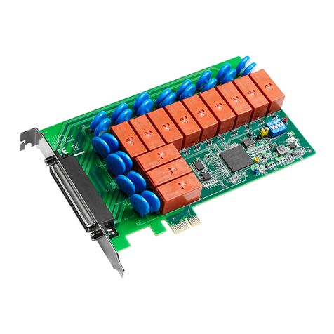
Advantech PCIE-1802 User manual

Advantech

Advantech PCIE-1802 User manual

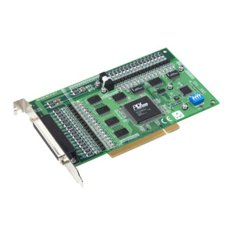
Advantech PCI-1761 User manual

Advantech

Advantech PCI-1761 User manual

Advantech PCI-1243U User manual

Advantech

Advantech PCI-1243U User manual

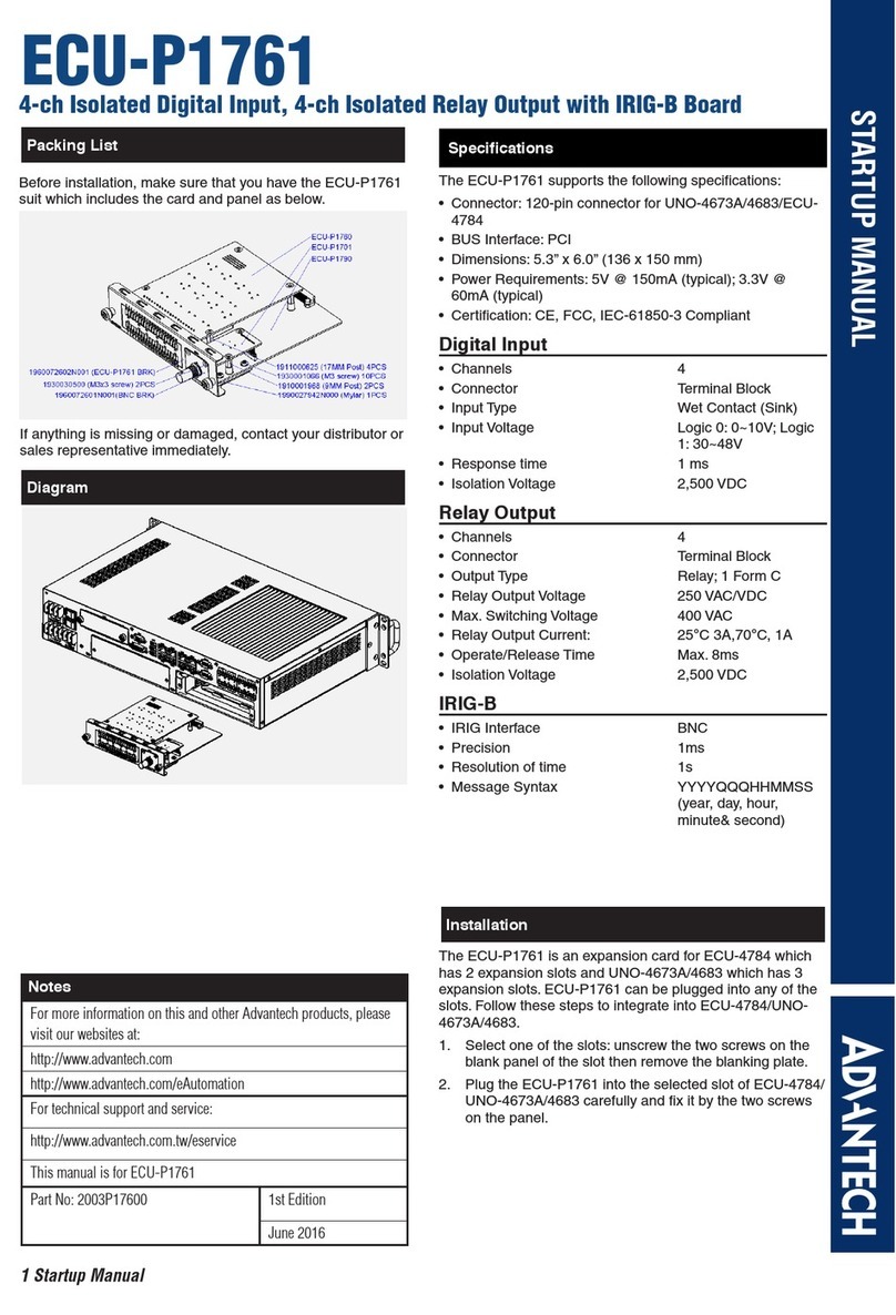
Advantech ECU-P1761 Installation and operation manual

Advantech

Advantech ECU-P1761 Installation and operation manual

Advantech PCI-1742U Installation and operation manual

Advantech

Advantech PCI-1742U Installation and operation manual

Advantech PCI-1761 User manual

Advantech

Advantech PCI-1761 User manual

Advantech MIC-3620 User manual

Advantech

Advantech MIC-3620 User manual

Advantech PCI-1737U Installation and operation manual

Advantech

Advantech PCI-1737U Installation and operation manual

Advantech PCI-1724U User manual

Advantech

Advantech PCI-1724U User manual

Advantech PCI-1713 User manual

Advantech

Advantech PCI-1713 User manual

Advantech PCI-1714UL Installation and operation manual

Advantech

Advantech PCI-1714UL Installation and operation manual

Advantech PCI-1737U User manual

Advantech

Advantech PCI-1737U User manual

Advantech PCLS-848-P User manual

Advantech

Advantech PCLS-848-P User manual

Popular PCI Card manuals by other brands

ICS Advent RB-24 product manual

ICS Advent

ICS Advent RB-24 product manual

SIIG SATA II-150 PCI Quick installation guide

SIIG

SIIG SATA II-150 PCI Quick installation guide

Addonics Technologies ADSA3GPX8-ML user guide

Addonics Technologies

Addonics Technologies ADSA3GPX8-ML user guide

Encore ENL-WI-G user guide

Encore

Encore ENL-WI-G user guide

Devolo MicroLink 56k PCI manual

Devolo

Devolo MicroLink 56k PCI manual

IOGear GICe720S3W6 installation guide

IOGear

IOGear GICe720S3W6 installation guide

TP-Link Archer TXE72E user guide

TP-Link

TP-Link Archer TXE72E user guide

TRENDnet TEW-423PI Quick installation guide

TRENDnet

TRENDnet TEW-423PI Quick installation guide

Xilinx Alveo U50 user guide

Xilinx

Xilinx Alveo U50 user guide

LevelOne GNC-0112 Quick installation guide

LevelOne

LevelOne GNC-0112 Quick installation guide

Crystal Vision GPI36 user manual

Crystal Vision

Crystal Vision GPI36 user manual

Avermedia GC570D Quick installation guide

Avermedia

Avermedia GC570D Quick installation guide

Conrad 1333474 operating instructions

Conrad

Conrad 1333474 operating instructions

Exsys EX-42062 user manual

Exsys

Exsys EX-42062 user manual

Vantec 2+1 Serial & Parallel PCI Host Card specification

Vantec

Vantec 2+1 Serial & Parallel PCI Host Card specification

Digium TE131 user manual

Digium

Digium TE131 user manual

StarTech.com PEXHDCAP60L user guide

StarTech.com

StarTech.com PEXHDCAP60L user guide

Pima Sentinel Installation and operating guide

Pima

Pima Sentinel Installation and operating guide

manuals.online logo
manuals.online logoBrands
  • About & Mission
  • Contact us
  • Privacy Policy
  • Terms and Conditions

Copyright 2025 Manuals.Online. All Rights Reserved.