Advantech DVP-7421BE User manual

1
DVP-7421BE
4Channel Triplex
MPEG-1/2/4
Video/Audio Codec Card

2
Copyright
This documentation and the software included with this product
are copyrighted 2007 by Advantech Co., Ltd. All rights are
reserved. Advantech Co., Ltd. reserves the right to make
improvements in the products described in this manual at any time
without notice. No part of this manual may be reproduced, copied,
translated or transmitted in any form or by any means without the
prior written permission of Advantech Co., Ltd. Information
provided in this manual is intended to be accurate and reliable.
However, ADVANTECH CO., LTD. assumes no responsibility for
its use, nor for any infringements of the rights of third parties,
which may result from its use.
Acknowledgments
IBM and PC are trademarks of International Business Machines
Corporation. MS-DOS, Windows, Microsoft Visual C++ and Visual
BASIC are trademarks of Microsoft Corporation. Intel and Pentium
are trademarks of Intel Corporation. Delphi and C++ Builder are
trademarks of Inprise Corporation.
CE notification
The DVP-7421BE, developed by ADVANTECH CO., LTD., has
passed the CE test for environmental specifications when shielded
cables are used for external wiring. We recommend the use of
shielded cables. This kind of cable is available from Advantech.
Please contact your local supplier for ordering information
On-line Technical Support
For technical support and service, please visit our support website
at:
http://www.advantech.com/support
PartNo.2066742100 1stEdition
PrintedinTaiwan July.2007
Rev. 0.1

3
Contents
CHAPTER 1 GENERAL INFORMATION ....................................... 5
1.1 INTRODUCTION................................................................ 6
1.2 PRODUCTION FEATURE.................................................... 7
1.3 PRODUCT SPEC ............................................................ 10
1.3.1 Hardware Requirements..................................11
1.3.2 Software Requirement......................................11
1.3.3 Block Diagram ...................................................11
1.3.4 Packing List....................................................... 12
1.3.5 Dimensions ....................................................... 12
1.3.6 OVERVIEW .................................................................. 14
1.3.7 CONNECTOR AND PIN DEFINITION ................................. 15
CHAPTER 2 PRODUCT INSTALLATION.................................... 19
2.1. INSTALL DRIVER &UTILITY CD....................................... 21
2.2. HARDWARE INSTALLATION.............................................. 26
2.3. INSTALL DRIVER FOR CAPTURE CARD............................... 27
2.4. DEMO PROGRAM FUNCTIONALITY ................................... 34
2.4.1 Channel Select............................................... 34
2.4.2 Video Standard.............................................. 35
2.4.3 Encoding Format........................................... 35
2.4.4 Resolution....................................................... 36
2.4.5 Encoding Mode.............................................. 36
2.4.6 Playback Mode.............................................. 37
2.4.7 Preview Mode................................................ 39
2.4.8 Snapshot......................................................... 40
2.4.9 Motion Detect................................................. 41
2.4.10 Setting
Æ
Save............................................... 43
2.4.11 Sensor Control............................................... 44
2.4.12 GPIO control................................................... 46
2.4.13 ENC control.................................................... 47
2.4.14 EE Control...................................................... 48
2.4.15 Convert Function........................................... 49
2.4.16 Multi-Board ID Reorganization.................... 50
CHAPTER 3 DVP-7421BE TRIPLEX EXPERIMENT.................... 52

4
3.1 PLATFORM:P4 PLATFORM............................................. 52
3.2 APPENDIX:MPEG4SOFTWARE DECODER....................... 54

5
CHAPTER
1
General Information

6
Chapter 1 General Information
1.1 Introduction
The DVP-7421BE is a high-end video capture board
with a hardware codec (simultaneous compression/
decompression, or encode/decode) engine. It supports
4-channel live preview, video/audio compression and
playback at D1 resolution and 120/100 fps. Up to four
DVP-7421BE boards can installed in one PC for
concurrent live viewing, compression and playback of
up to 16 channels at D1 resolution and 480/400 fps.
The programmer can use the comprehensive SDK to
load protection code or system parameters into the
on-board 128-byte EEPROM. The SDK comes with
sample code for reference. The hardware codec engine
makes the DVP-7421BE the ideal platform for
applications like network video servers, Video
conferencing and high-end digital video recorders.

7
1.2 Production Feature
The photo is the main interface of DVP-7421BE sample
program. The DVP-7421BE feature is like below:
A. EEPROM function ready product
Customer can write the value in EEPROM and check
the value before surveillance software boot up. System
Integrator can design protection to protect software
system. Valid offset values are between 0-127,Valid
output values are in the range of 0 and 255.
B. Full D1,real time,MPEG1/2/4,Video and
Stereo Audio Hardware Encode
The DVP-7421BE support the full D1 resolution, real
time (encode frame rate 30 fps). Moreover, the
DVP-7421BE can encode the stereo audio input to
MPEG1-LayerII format.
C. Full D1,real time,MPEG1/2/4,Video and
Stereo Audio Hardware Decode
Like encode model, the DVP-7421BE can decode D1
resolution, real time, and stereo audio out. The user
can easily playback the compression by the

8
DVP-7421BE hardware capability.
D. Software Decoder to AVI
The DVP-7421BE support software decode that can
convert compression MPEG file to AVI format (*.Divx).It
is convenient for customer integrate the function to their
software system.
E. GPIO access control
User can integrate the DI/DO device, like warning
alarm or IR sensor. The demo program can show and
feedback the signal information connection or not. It’s a
function good for SI combine various device to
establish powerful surveillance system.
F. Smart Quad Real-time Raw Data Preview
This special characteristic function can support the user
raw data to further advantage. For example, one can
use the function in the domain of intelligent analysis,
image comparison and optical Inspection, etc. The
Smart Quad raw data can provide the 4CIF video files
that combined in D1 resolution block. The customer
also can choices one of Quad to advance operation.
G. Hardware Motion Detection
The DVP-7421BE hardware support motion detection.
User can set nine areas to monitor the video changes.
The degree of changes could set by library code. It is a
benefit for software develops less effort on motion
function.

9
H. Video Configuration
The DVP-7421BE can configure the most feature of
video. User can set GOP frames, GOP type, Video
Format, Frame rate, Video Bit rate, Average Video Bit
Rate, Audio Bit rate, Audio Sampling rate, etc.
10
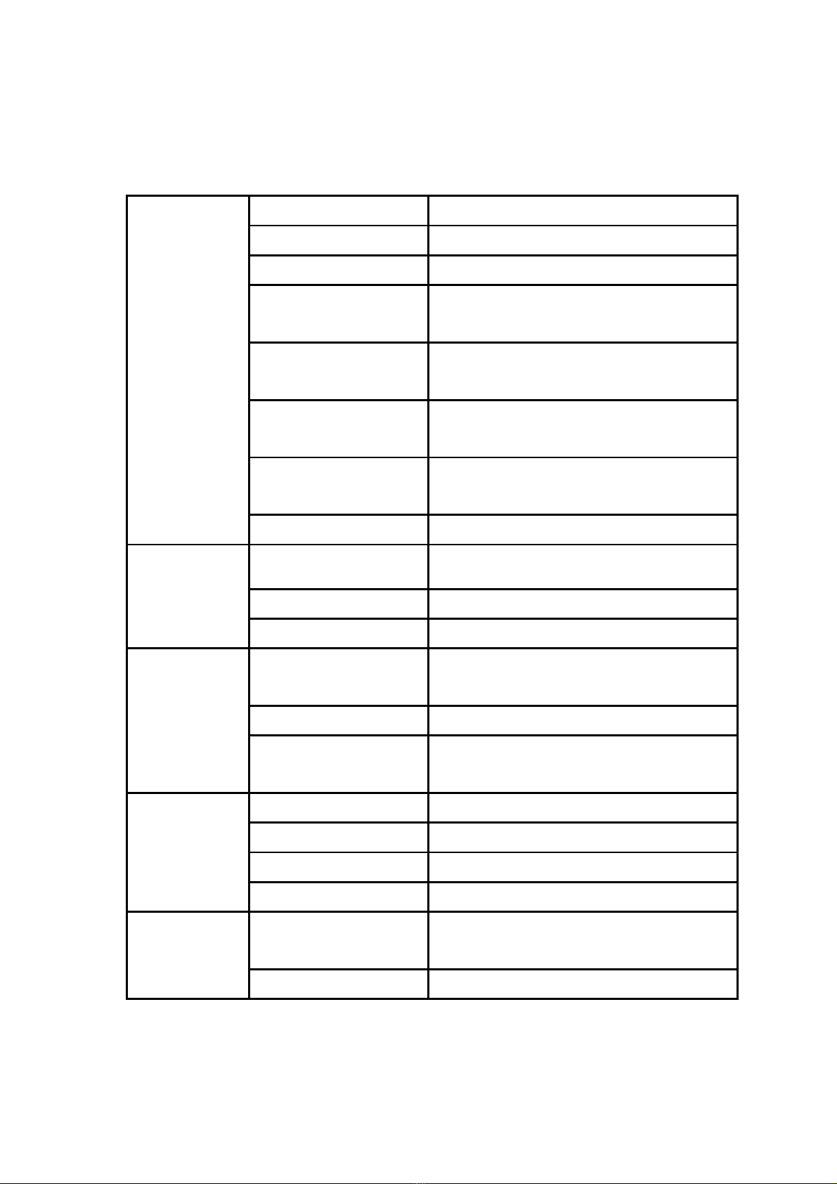
1.3 Product Spec
Video Standard Composite for NTSC/PAL
Video Input 4 x BNC connectors
Capture Resolution D1 (NTSC: 720 x 480; PAL: 720 x 576)
Frame Rate 30/25 fps (NTSC/PAL) for each channel
(total 120/100 fps @ D1 resolution)
Image Processing Hardware adjustment of hue, contrast,
saturation, and brightness
Video
Encoding/Decoding
MPEG-1/2/4 (CBR/VBR 128 kbps to 15
Mbps)
Video Output PCI preview/playback stream
Analog video out from Smart Quad
Video
Video Loop-through 4 X BNC Connectors
Audio Input 4 x stereo inputs (8 x BNC connectors)
Audio Output 4 x stereo outputs from decoder
Audio
Audio Encoding Supports MPEG1-Layer II
Operating System Supports Microsoft Windows XP and
Windows 2000
DirectX Required Version 9 or above
Software
Development
Kit Demo Program Complete demo program with VC++
sample code for reference
Host Interface PCI bus
Max. Card 4
DIO TTL/CMOS level 3.3 V, 4 DI/4 DO
Hardware
Power Consumption 5 V DC @ 3 A , 12 V DC @ 0.5 A
Temperature -10 ~ 60° C, Operating -20 ~ 70° C,
Non-operating
Environment
Dimensions (W x L) 182.6 x 106.9 mm (7.2" x 4.2")
Table 1.1 Product spec

11
1.3.1 Hardware Requirements
CPU:Intel Pentium III 800MGHz or above
RAM:256 MB SD RAM or above
PCI slot:One PCI Slot or above
VGA:AGP 4X above
1.3.2 Software Requirement
Support Microsoft DirectX 9 or above
Microsoft Windows 2000/XP
Support Complete demo program with VC++
Builder programming language sample code for
reference
1.3.3 Block Diagram
Figure 1.1 Block diagram
12
1.3.4 Packing List
1 x DVP-7421BE video codec card P/N:9692742100E
1 x Drive & Utility CD
P/N:2066742100
2 x 30 cm Dsub-15 to 8 x BNC
connector
P/N:1700001618
Board product warranty card P/N:2190000902
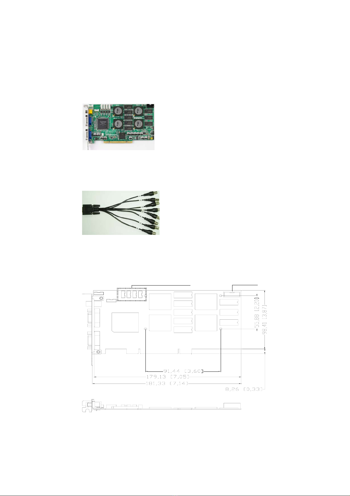
1.3.5 Dimensions
4 x Decoder Audio Out 4 DI/4 DO
Figure 1.2 Dimensions
13
Figure 1.3 Bracket I/O definition

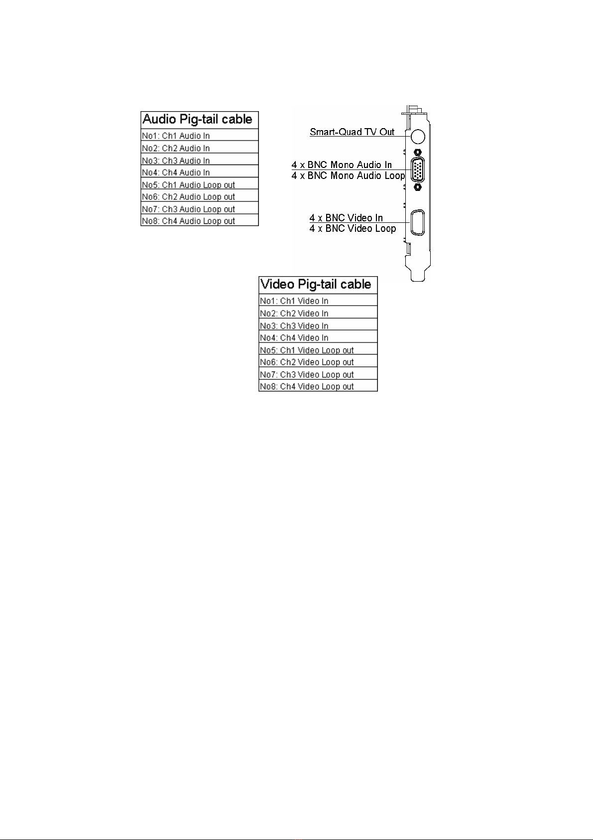
14
1.3.6 Overview
Smart-Quad TV Out 4 x BNC Mono Audio In
4 x BNC Mono Audio Loo
p
4 x BNC Video In
4 x BNC Video Loo
p
Extra Audio In
p
ut
Extra Audio Out
p
ut DIO Connecto
r
ODM Onl
y
Extra Video In
p
ut
Smart-Quad TV Out
4 x BNC Mono Audio In
4 x BNC Mono Audio Loo
p
4 x BNC Video In
4 x BNC Video Loo
p
Extra Video Out
p
ut
Stereo (L/R)
Stereo (L/R)

15
1.3.7 Connector and Pin Definition
A. Extra Video Output
Pin Type Def
1 Out Video 1 Out
2 Out Video 2 Out
3 Out Video 3 Out
4 Out Video 4 Out
5 - GND
B. Extra Video Input
Pin Type Def
1 In Video 1 In
2 In Video 2 In
3 In Video 3 In
4 In Video 4 In
5 - GND
16
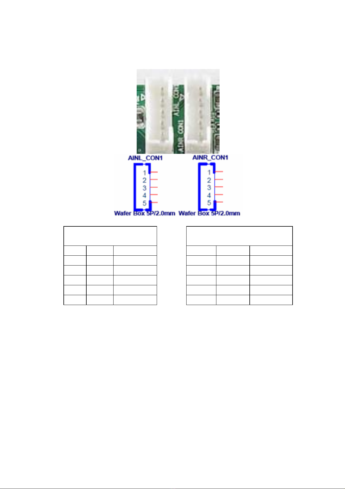
C. Extra Audio Input (Stereo L/R)
Audio Left Channel
Input CON Audio Right Channel
Input CON
Pin Type Def Pin Type Def
1 In Audio L1 1 In Audio R1
2 In Audio L2 2 In Audio R2
3 In Audio L3 3 In Audio R3
4 In Audio L4 4 In Audio R4
5 - GND 5 - GND

17
D. Extra Audio Output (Stereo L/R)
Audio Left Channel
Output CON Audio Right Channel
Output CON
Pin Type Def Pin Type Def
1 Out Audio L1 1 Out Audio R1
2 Out Audio L2 2 Out Audio R2
3 Out Audio L3 3 Out Audio R3
4 Out Audio L4 4 Out Audio R4
5 - GND 5 - GND

18
E. DI/O connector
Pin Type Def
1 Out GPIO 4
2 Out GPIO 5
3 Out GPIO 6
4 Out GPIO 7
5 In GPIO 0
6 In GPIO 1
7 In GPIO 2
8 In GPIO 3
9 - VCC
10 - GND

19
2
Product Installation
CHAPTER

20
Chapter 2 Product Installation
To facilitate the installation of the DVP-7421BE device
drivers and utility software, you should read the
instructions in this chapter carefully before you attempt
installation. The device drivers and demo program for
the DVP-7421BE board are located on the 「Driver &
Utility CD」.
Please install Driver & Utility software before install
hardware into PCI slot.
Table of contents
Other Advantech Video Card manuals


Popular Video Card manuals by other brands


Tech Source
Tech Source RAPTOR DL-LITE - DRIVERS FOR HP-UX... Installation and reference manual

EVGA
EVGA GeForce GT 430 SuperClocked Specifications

Diamond Multimedia
Diamond Multimedia Diamond Viper HD 2600XT PCIE Specification sheet

3Dlabs
3Dlabs Workstation x1000 user guide

Gigabyte
Gigabyte GV-NX62TC256DS user manual

AMD
AMD FirePro W600 user guide


