AE RC8 B3e User manual

2
:: Introduction
:: KIT Features
:: Additional
:: Other Helpful Items
Associated Electrics, Inc.
26021 Commercentre Dr.
Lake Forest, CA 92630
http://www.TeamAssociated.com · http://www.RC10.com · http://twitter.com/Team_Associated · http://bit.ly/AEonFacebook
Customer Service
Tel: 949.544.7500
Fax: 949.544.7501
Thank you for purchasing this Team Associated product. This assembly manual contains instructions and tips for building and
maintaining your new RC8B3e Kit. Please take a moment to read through this manual to help familiarize yourself with these steps.
We are continually changing and improving our designs; therefore, actual parts may appear slightly different than in the
illustrations. New parts will be noted on supplementary sheets located in the appropriate parts bags.
Check each bag for these sheets before you start to build.
RC8B3e Team Kit #80916 Features:
• 7075-T6 hard anodized aluminum chassis features an optimized weight bias layout for improved handling and stability
• Front suspension features pillow ball uprights for increased adjustability and improved durability
• Light weight ring gears and optimized precision ball bearing sizing, reduces drivetrain rotational mass for improved acceleration
and battery efficiency
• Gearboxes feature a 3.38:1 internal gear ratio with fast access differentials for quick removal, tuning and maintenance
• Six universal drive shafts for efficient drivetrain power delivery and ease of maintenance
• 7075-T6 aluminum 16mm “Big Bore” threaded shocks with TiN coated 3.5mm shafts, larger diameter precision springs, and
optimized bladders for more precise volume compensation
• 7075-T6 aluminum shock towers front and rear feature finely tuned shock mounting and upper arm positions
• Refined suspension geometry with lower hinge pin inserts for quick and easy roll center adjustments
• Light weight one-piece wing mounts feature height and forward positioning adjustment for more precise handling
• Two piece sliding motor mount for easy gear mesh adjustment and motor removal
• Proline RC8B3e clear body and Team Associated molded wing included
• The RC8B3e shares over 95% parts compatibility with the RC8B3 nitro buggy, offering the perfect solution for multi-class racers
Your new RC8B3e Kit comes as a kit. There are some items you will need to complete your kit (refer to catalog for suggestions):
• 2 channel radio/transmitter set with switch – FM/PCM/2.4GHz recommended
• Transmitter batteries (#302 recommended)
• Steering servo (#29133, 29134, 29166, 29167, 29168, 27100, 27101 recommended)
• 14.8v LiPo battery pack (#311, 318, 756, 757 recommended)
• Quick charger (#616, 27200 recommended)
• 1/8 scale specific electronic speed control
• 1/8 scale specific electric motor (#988, 989, 993 recommended)
• 1/8th scale buggy tires • CA (Cyanoacrylic) glue (#1597 recommended)
• Polycarbonate specific spray paint or polycarbonate specific bottled paint and airbrush
• Thread locking compound (#1596 recommended) • Needle nose pliers • Shock shaft pliers (#1675 recommended)
• Hobby knife • Reamer/hole punch • Ride height gauge (#1449 recommended)
• Silicone shock/Diff fluids (Refer to catalog for complete listings) • Body scissors (AE #1737)
• FT turnbuckle wrench (AE #89240) • Soldering iron • Wire cutters
• FT hex wrenches (AE #1655) • Calipers or precision ruler
• FT nut drivers (AE #1663-1668) • Green Slime shock lube (AE #1105)

3
:: Hardware - 1:1 Scale View
2.5x6mm (4675)
2.5x8mm (31448)
3x6mm (31541)
3x8mm (25201)
Titanium (91592)
3x10mm (25202)
Titaniuim (91593)
3x12mm (25203)
Titanium (91594)
3x14mm (89208)
Titanium (91595)
4x10mm (81262)
4x12mm (89214)
4x14mm (89217)
4x16mm (81263)
4x20mm (81264)
Flat Head (fhcs)
2x5mm (31511)
2x16mm (7184)
3x8mm (89223)
3x10mm (25620)
3x24mm (89225)
Socket Head (shcs)
2.5x6mm (31520)
2.5x8mm (31521)
2.5x18mm (81259)
3x6mm (31531)
Titanium (91580)
3x10mm (25211)
3x14mm (25187)
Titanium (91584)
3x16mm (89203)
Titanium (91585)
3x20mm (25188)
3x24mm (89204)
Titanium (91589)
4x14mm (81260)
4x16mm (81261)
Button Head (bhcs)
3x3mm (25225)
3x6mm (81257)
3x10mm (4671)
3x12mm (81258)
4x4mm (7732)
5x4mm (89221)
Set Screws
5x8x2.5mm (89161)
5x10x4mm (91560)
6x10mm (31404)
6x12x4mm (91561)
8x16x5mm (91564)
8x16x5mm flanged
(91565)
Ball Bearings

4
:: Table of Contents
1................... Cover
2................... Introduction
3................... 1:1 Hardware “Fold Out”
4................... Table of Contents
5 - 7..............Differentials Build
(Bag A, B, C)
7 - 8...........Steering / Chassis Build
(Bag D, E)
9 - 10...........Front Gearbox Build
(Bag F, G)
11 - 12.........Front Uprights Build
(Bag H, I)
12 - 14........Rear Gearbox Build
(Bag J, K)
15 - 16........Rear Uprights / Turnbuckles
Build (Bag L)
16.................Center Bulkhead Build
(Bag M, N)
17 - 18 .......Anti-Roll Bars Build (Bag O)
18 - 19........Shocks Build (Bag P, Q)
20.................Battery Tray Build (Bag R)
21.................Receiver Box / Linkage Build
(Bag S)
22................Tire/Body Build
(Misc. Bag)
23.................Droop Settings
24 - 33.......Catalog
34................Back Cover
Associated Electrics, Inc.
26021 Commercentre Dr.
Lake Forest, CA 92630
http://www.TeamAssociated.com · http://www.RC10.com · http://twitter.com/Team_Associated · http://bit.ly/AEonFacebook
Customer Service
Tel: 949.544.7500
Fax: 949.544.7501
:: Notes
There is a 1:1 hardware foldout page in the
front of the manual. To check the size of a part,
line up your hardware with the correct drawing
until you find the exact size. Each part in the
foldout has a number assigned to it for ordering
replacement parts.
This symbol indicates a special
note or instruction in the manual.
Scanning this QR code will take
you to Team Associated’s Tech Tips
videos. These videos will help you
with your build and setup!
This symbol indicates a Racers Tip.
!

:: Differential Build (Front and Rear) - Bag A, B, C - Step 2
:: Differential Build (Front and Rear) - Bag A, B, C - Step 3
5
:: Differential Build (Front and Rear) - Bag A, B, C - Step 1
6/15
Align pin with
groove in sun gear
!
89120
Diff
Outdrive
Pin
89120
Diff
Outdrive
Pin
Racer’s Tip:
Use black grease
(#6588) to
lube the O-Rings
before installation!
81008
Diff
Outdrives
81008
Diff
Outdrives
89121
Diff O-Ring
Set
89121
Diff O-Ring
Set
89121
Diff O-Ring
Set
89121
Diff O-Ring
Set
89120
Diff
Shims
89120
Diff
Shims
89120
Diff
Planet
Gears
89120
Diff Sun
Gear
91564
8x16x5
Bearing
91564
8x16x5
Bearing
89115
Diff
Housing
81002
Diff Ring
Gear, 44T
x2
x2
Racer’s Tip:
Use black grease
(#6588) to
lube the O-Rings
before installation!

6
:: Differential Build (Front and Rear) - Bag A, B, C - Step 4
:: Differential Build (Center) - Bag A, B, C - Step 5
:: Differential Build (Center) - Bag A, B, C - Step 6
Align pin with
groove in sun gear
!
89208
3x14mm
FHCS
x4
Diff Fluid
89116
Diff
Gasket
89120
Diff
Outdrive
Pin
Front Diff Fluid:
10,000cst #5455
Rear Diff Fluid:
7,000cst #5454
81008
Diff
Outdrives
89121
Diff O-Ring
Set
89121
Diff O-Ring
Set
89120
Diff
Shims
89120
Diff
Planet
Gears
89120
Diff Sun
Gear
89120
Diff Sun
Gear
91564
8x16x5
Bearing
x2
Racer’s Tip:
Fill diff to the top of
the planet gear pins.
89115
Diff
Housing
Racer’s Tip:
Use black grease
(#6588) to coat
the Diff Gasket
before installation!
Racer’s Tip:
Use black grease
(#6588) to
lube the O-Rings
before installation!
7
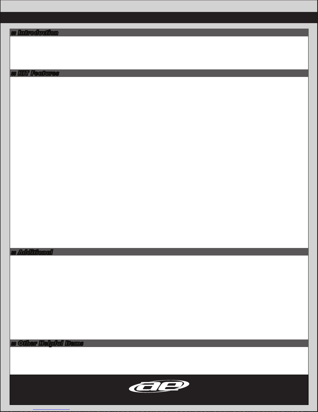
:: Differential Build (Center) - Bag A, B, C - Step 7
:: Differential Build (Center) - Bag A, B, C - Step 8
:: Steering / Chassis Build - Bag D, E - Step 1
89519
Plastic
Spur Gear,
46T
89120
Diff
Outdrive
Pin
81008
Diff
Outdrives
89121
Diff O-Ring
Set
89121
Diff O-Ring
Set
89120
Diff
Shims
91564
8x16x5
Bearing
x2
Racer’s Tip:
Use black grease
(#6588) to
lube the O-Rings
before installation!
89208
3x14mm
FHCS
x4
Diff Fluid
89116
Diff
Gasket
Center Diff Fluid:
10,000cst #5455
89120
Diff Sun
Gear Racer’s Tip:
Use black grease
(#6588) to coat
the Diff Gasket
before installation!
Racer’s Tip:
Fill diff to the top of
the planet gear pins.
81091
Steering
Post
25201
3x8mm
FHCS
25201
3x8mm
FHCS
25201
3x8mm
FHCS
25201
3x8mm
FHCS
25201
3x8mm
FHCS
31541
3x6mm
FHCS
31541
3x6mm
FHCS 81262
4x10mm
FHCS
81001
Side
Guards 81295
RC8B3e
Chassis
x2
x2
x2
x2 x2
x2
#1596
thread lock

8
:: Steering / Chassis Build - Bag D, E - Step 2
:: Steering / Chassis Build - Bag D, E - Step 3
:: Steering / Chassis Build - Bag D, E - Step 4
89161
5x8x2.5mm
Bearing
25201
3x8mm
FHCS
81088
Steering
Bellcrank
Nut
81093
Turnbuckle
Ball, 4mm
81089
Steering
Rack
x4
x2
x2
x2
81087
Servo
Saver
Tube 81087
Servo
Saver
Shim
31404
6x10x3mm
Bearing
25211
3x10mm
BHCS
81087
Servo
Saver
Spring
81087
Servo Saver
Spring
Retainer
31511
2x5mm
SHCS
1mm
81086
Steering
Bellcrank
81086
Steering
Bellcrank
81086
Steering
Bellcrank
x2
x4 x2
#1596
thread lock
#1596
thread lock
#1596
thread lock
!
Tighten 2x5mm SHCS snug.
Set servo saver tension to
1mm. Then tighten 2x5mm
SHCS to lock.
Kit Setup:
1
2
3
4
5
Racer’s Tip:
Use black grease
(#6588) to lube
the bellcrank halves
before installation!

9
:: Front Gearbox Build - Bag F, G - Step 1
:: Front Gearbox Build - Bag F, G - Step 2
:: Front Gearbox Build - Bag F, G - Step 3
81260
4x14mm
BHCS
81060
Hinge
Pin
89317
Droop
Screw
81054
Front Arm
Shim, 1mm
89221
5x4mm
Set Screw
81020
Center
Universal,
(76mm)
81015
Gearbox,
(Inboard)
81015
Dust Cap
x2
91561
6x12x4mm
Bearing
25620
3x10mm
SHCS
89117
Diff Shim
81050
Arm Mount
Insert,
Center
81054
Front Arm,
Lower
81046
Arm
Mount (B)
4675
2.5x6mm
FHCS
81003
Diff Pinion
Gear, 13T
x2
x2
x2
x2
81015
Gearbox,
(Outboard)
81015
Anti-Roll
Bar Cap
81259
2.5x18mm
BHCS
#1596
thread lock
Kit Setup:
!
Note that each arm is
marked with a R for the
Right Arm or an L for
the Left Arm.
Racer’s Tip:
Use black grease
(#6588) to
lube the Diff Pinion
before installation!
Racer’s Tip:
Use black grease
(#6588) to
lube the Diff Ring
before installation!

10
:: Front Gearbox Build - Bag F, G - Step 4
:: Front Gearbox Build - Bag F, G - Step 5
:: Front Gearbox Build - Bag F, G - Step 6
#1596
thread lock
#1596
thread lock
81260
4x14mm
BHCS
25201
3x8mm
FHCS
89214
4x12mm
FHCS
89214
4x12mm
FHCS
89216
M4
Locknut
81049
Upper Link
Mount
81055
Caster
Clip, 2mm
81055
Caster
Clip, 1mm
89214
4x12mm
FHCS
81026
Shock Tower,
Front
x2
x2 x2
81112
Body Post,
Front
25201
3x8mm
FHCS
81032
Chassis
Brace,
Front
81030
Top Plate
81050
Arm Mount
Insert,
Center
81050
Arm Mount
Insert,
Center
89225
3x24mm
SHCS
81196
Shock
Bushing
81055
Front
Upper Arms
81060
Hinge Pin,
Front Upper
x2
x2
x2
x2
x2
x4
81045
Arm Mount
(A)
81050
Arm Mount
Insert,
Middle Down
x2
81050
x2
x2
x2
x2
Caster
Clips
1mm 2mm
Kit Setup:
Kit Setup: Kit Setup:
!
Note that each arm is
marked with a R for the
Right Arm or an L for
the Left Arm.
11
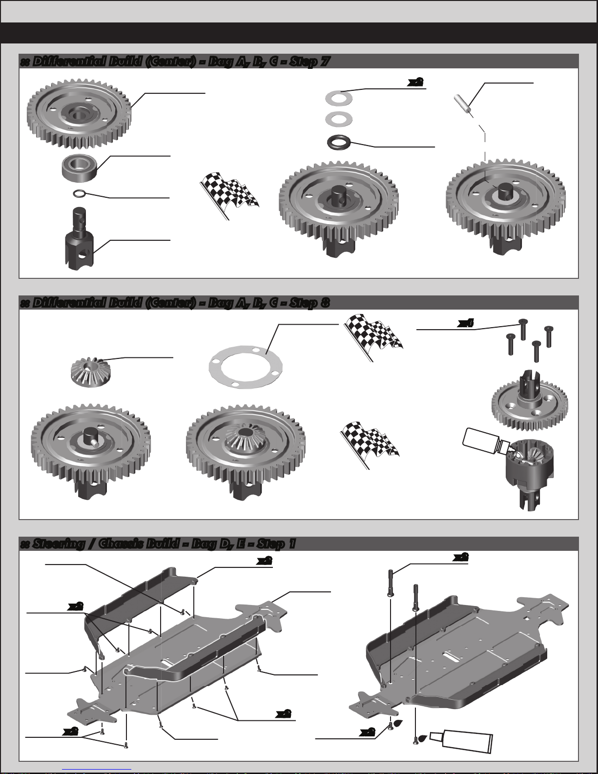
:: Front Uprights Build - Bag H, I - Step 1
:: Front Uprights Build - Bag H, I - Step 2
:: Front Uprights Build - Bag H, I - Step 3
81065
Pillow
Ball Cap
81056
Suspension
Arm
Endcap
81066
Steering
Block Arm
25211
3x10mm
BHCS
x2
x2
81070
Pillow
Ball Nut,
Aluminum
81072
Pillow
Ball Shim
(2 degree)
81072
Pillow
Ball Shim
(0.5 degree)
25202
3x10mm
FHCS
81067
Pillow
Ball, Steel
81093
Turnbuckle
Ball, 4mm
x2
x2
x2
#1596
thread lock
#1596
thread lock
91565
8x16x5mm
Bearing,
Flanged
81065
Steering
Block
25225
3x3mm
Set Screw
89221
5x4mm
Set Screw
81081
Hex Drive,
17mm
(Blue)
89096
Wheel
Hex Pin
81019
Universal,
(93.5mm)
x2
Pillow Ball Shims
0.5° 1° 2°
!
!
Tighten pillow ball nut
(#81070) until pillow ball
(#81067) begins to bind,
then loosen until pillow ball
moves freely.
Use Pillow Ball Shims
(#81072) to adjust camber.
12
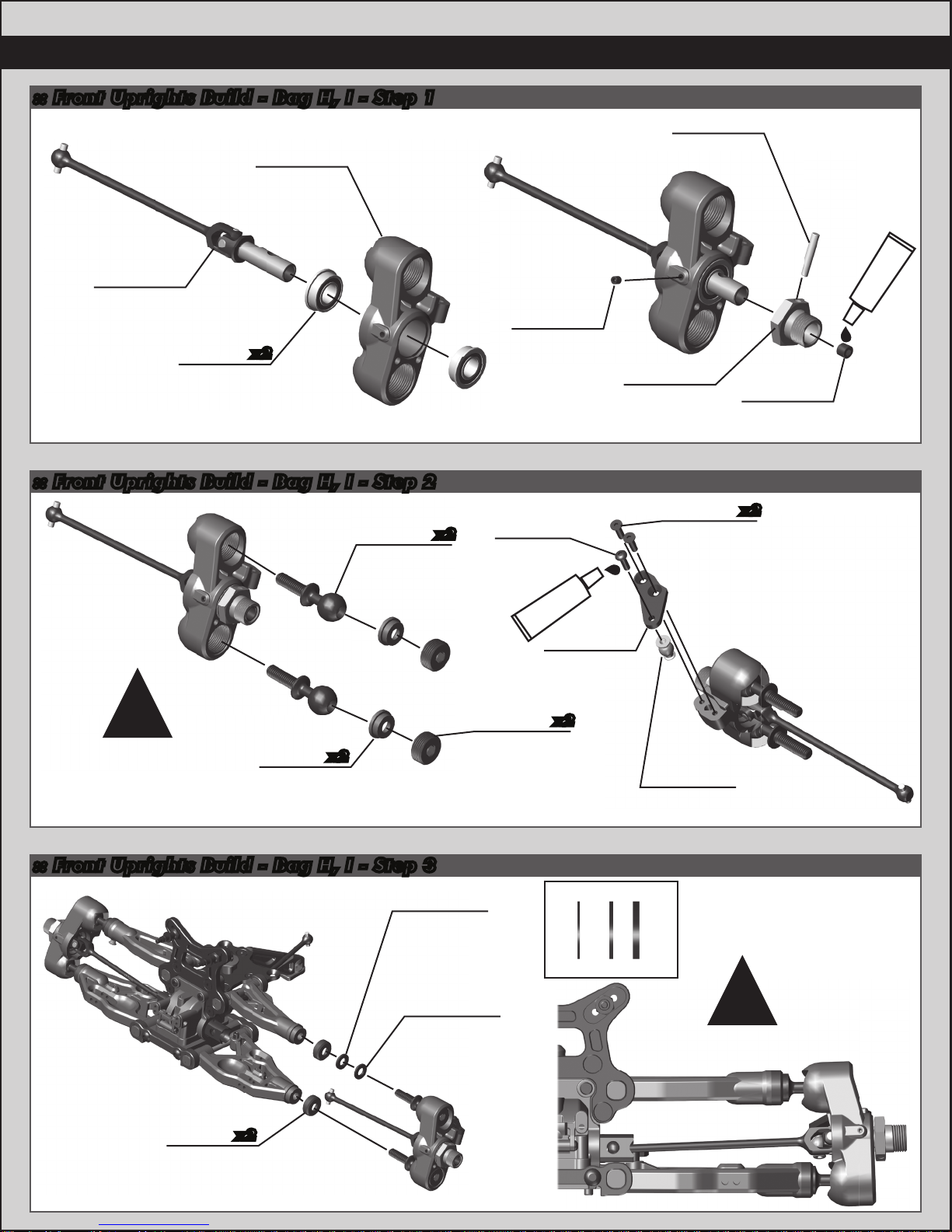
:: Front Uprights Build - Bag H, I - Step 4
:: Rear Gearbox Build - Bag J, K - Step 1
89214
4x12mm
FHCS
81264
4x20mm
FHCS
81113
Front
Bumper
x2
x2
89221
5x4mm
Set Screw
81021
Center
Universal,
(106mm)
81015
Gearbox,
(Inboard)
81015
Dust Cap
91561
6x12x4mm
Bearing
4675
2.5x6mm
FHCS
81003
Diff Pinion
Gear, 13T
x2
:: Rear Gearbox Build - Bag J, K - Step 2
25620
3x10mm
SHCS
89117
Diff Shim
x2
x2
81015
Gearbox,
(Outboard)
81015
Anti-Roll
Bar Cap
81259
2.5x18mm
BHCS
#1596
thread lock
Racer’s Tip:
Use black grease
(#6588) to
lube the Diff Pinion
before installation!
Racer’s Tip:
Use black grease
(#6588) to
lube the Diff Ring
before installation!
#1596
thread lock
81262
4x10mm
FHCS
89216
M4
Locknut
x2
89214
4x12mm
FHCS

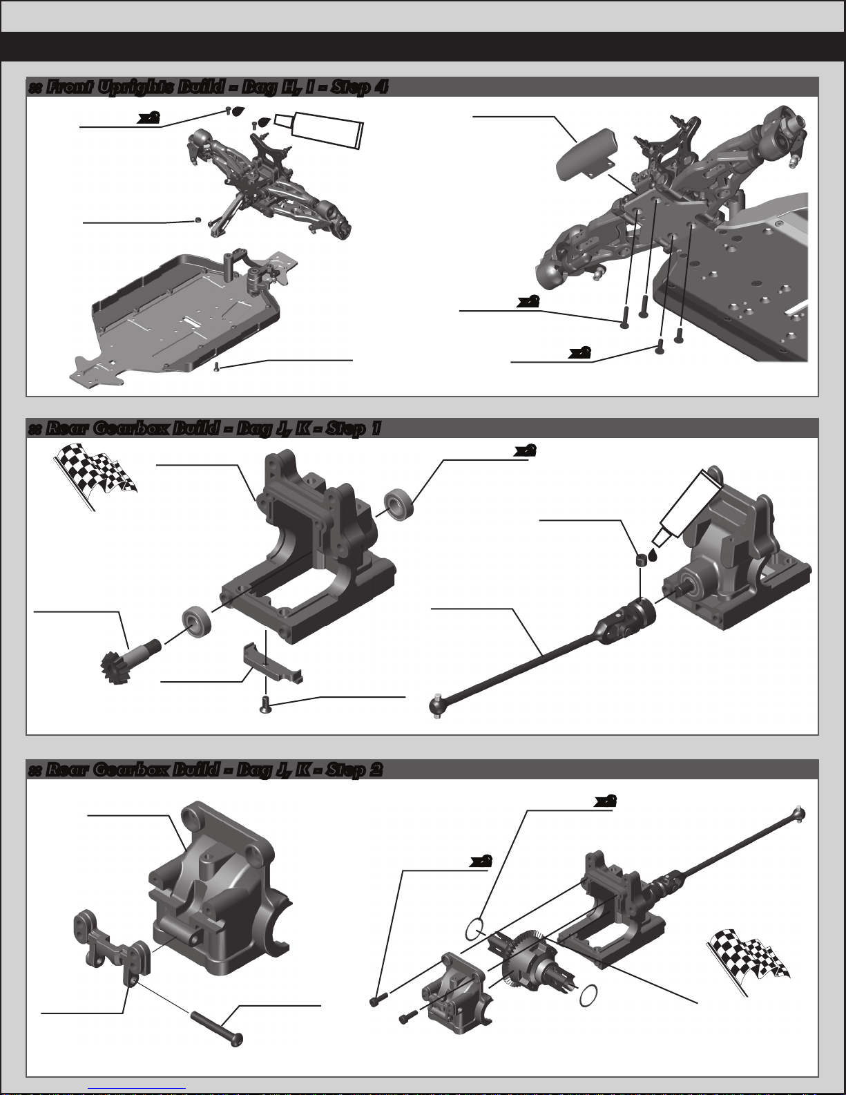
13
:: Rear Gearbox Build - Bag J, K - Step 3
:: Rear Gearbox Build - Bag J, K - Step 4
:: Rear Gearbox Build - Bag J, K - Step 5
81260
4x14mm
BHCS
81260
4x14mm
BHCS
81060
Hinge
Pin
25188
3x20mm
BHCS
81058
Rear Arm
Shim
81048
Arm
Mount
(D)
31531
3x6mm
BHCS
x2
x2
x2
81050
Arm Mount
Insert,
Center
81050
Arm Mount
Insert
(Center, Down)
89214
4x12mm
FHCS
25215
M3
Locknut
81032
Chassis
Brace
Mount
81032
Chassis
Brace,
Rear
81047
Arm
Mount (C)
81058
Rear Arm
89317
Droop
Screw
81059
Rear Arm
Mud Guard
x2
x2
x2
Kit Setup:
!
Note that each arm is
marked with a R for the
Right Arm or an L for
the Left Arm.
Kit Setup:
14
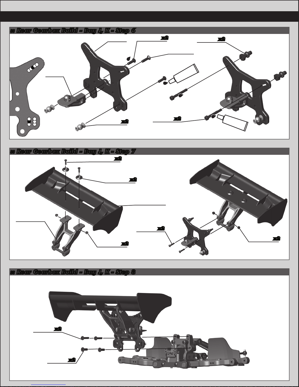
:: Rear Gearbox Build - Bag J, K - Step 7
:: Rear Gearbox Build - Bag J, K - Step 8
:: Rear Gearbox Build - Bag J, K - Step 6
81112
Body
Post,
Rear
81108
Wing
Mount,
High
81027
Shock
Tower,
Rear
81094
Upper Link
Mount
25203
3x12mm
FHCS
81106
Wing
Mount
Button 81106
Wing
25215
M3
Locknut
25215
M3
Locknut
25211
3x10mm
BHCS 25203
3x12mm
FHCS
x2
x2
x2
x2
x2
x2
89225
3x24mm
SHCS
2308
3x18mm
BHCS
89214
4x12mm
FHCS
81263
4x16mm
FHCS
81196
Shock
Bushing
x2
x2
x2
x2
x2
#1596
thread lock
#1596
thread lock
1 4
2 5
3 6
2
1
345
Kit Setup:

15
:: Rear Uprights / Turnbuckles Build - Bag L - Step 1
:: Rear Uprights / Turnbuckles Build - Bag L - Step 2
:: Rear Uprights / Turnbuckles Build - Bag L - Step 3
25225
3x3mm
Set Screw
81094
Rod End,
5mm
81094
Rod End,
5mm
25215
M3
Locknut
81075
Rear Hub
Shim, 1.0mm
25215
M3
Locknut
89269
Steel
Turnbuckle,
38mm
89096
Wheel
Hex Pin
81081
Hex Drive,
17mm
(Blue)
89221
5x4mm
Set Screw
81075
Rear Hub
Shim, 2.5mm
81075
Rear Hub
Shim, 1.5mm
81076
Hub Hinge
Pin
89204
3x24mm
BHCS
81075
Rear Hub
Rear Hub Turnbuckle
14.50mm (0.57”)
Hub Hinge
91565
8x16x5mm
Bearing,
Flanged
81018
Universal,
(90.5mm)
x2
Kit Setup:
Mount the rear camber link in
the outside hole on the rear hub.
#1596
thread lock
Kit Setup:
Mount the rear hub to the rear
arm in the lower hole.
Kit Setup:
Kit Setup:
89216
M4
Locknut
81264
4x20mm
FHCS
89214
4x12mm
FHCS
x3

16
:: Center Bulkhead / Brakes Build - Bag M, N- Step 2
:: Center Bulkhead / Brakes Build - Bag M, N- Step 1
:: Rear Uprights / Turnbuckles Build - Bag L - Step 4
81093
Rod End,
4mm
89526
4x50mm
Turnbuckle
81093
Rod End,
4mm
Steering Turnbuckle
26.40mm (1.04”)
Motor
not
included!
Motor
pinion not
included!
31532
3x8mm
BHCS
25211
3x10mm
BHCS
89206
4x10mm
BHCS
25224
4x4mm
Set Screw
81300
RC8B3e Motor
Mount Slide
81304
RC8B3e
Bulkhead
Cover
x2
x4
x2
#1596
thread lock
#1596
thread lock
81262
4x10mm
FHCS
31448
2.5x8mm
FHCS
81304
RC8B3e Center
Bulkhead
81299
RC8B3e
Motor Mount
81304
RC8B3e
Wire Guide
x4
#1596
thread lock

17
:: Anti-Roll Bars Build - Bag 0 - Step 3
:: Anti-Roll Bars Build - Bag 0 - Step 2
:: Anti-Roll Bars Build - Bag 0 - Step 1
Center the Anti-Roll
Bar Collet on the
Anti-Roll Bar, then
tighten the (#25225)
3x3mm set screw.
!
#1596
thread lock
25225
3x3mm
Set Screw
81150
Anti-Roll
Bar
Collet
81130
(Front) Anti-Roll
Bar, Green (2.4mm)
81140
(Rear) Anti-Roll
Bar, Blue (2.7mm)
Build front
and rear
Anti-Roll Bars
89203
3x16mm
BHCS
x2
Rear Hub Turnbuckles
removed for view clarity.
!
Build front
and rear
Anti-Roll Bars
89203
3x16mm
BHCS
x2 Steering Turnbuckles
removed
for view clarity.
When Installing the
set screw into the
rod ends, tighten to
6mm. Tightening
past 6mm can
damage rod end!
!
!
31521
2.5x8mm
BHCS
25225
3x3mm
Set Screw
x2
x2
81257
3x6mm
Set Screw
x2
Tighten #81257 set screws
just enough to still allow the
anti-roll bar to move freely.
!
#1596
thread lock
#1596
thread lock
Left Side Right Side
Anti-Roll Bar Pivots:
Tighten the Anti-Roll Bar
Rod Ends completely, then
offset the Anti-Roll bar rod
ends as seen above
(approximately 45 degrees).
!
81150
Anti-Roll
Bar Pivot
81150
Anti-Roll
Bar Rod
End
81150
Rod End
Ball
81258
3x12mm
Set Screw
x2
6mm
6mm
18
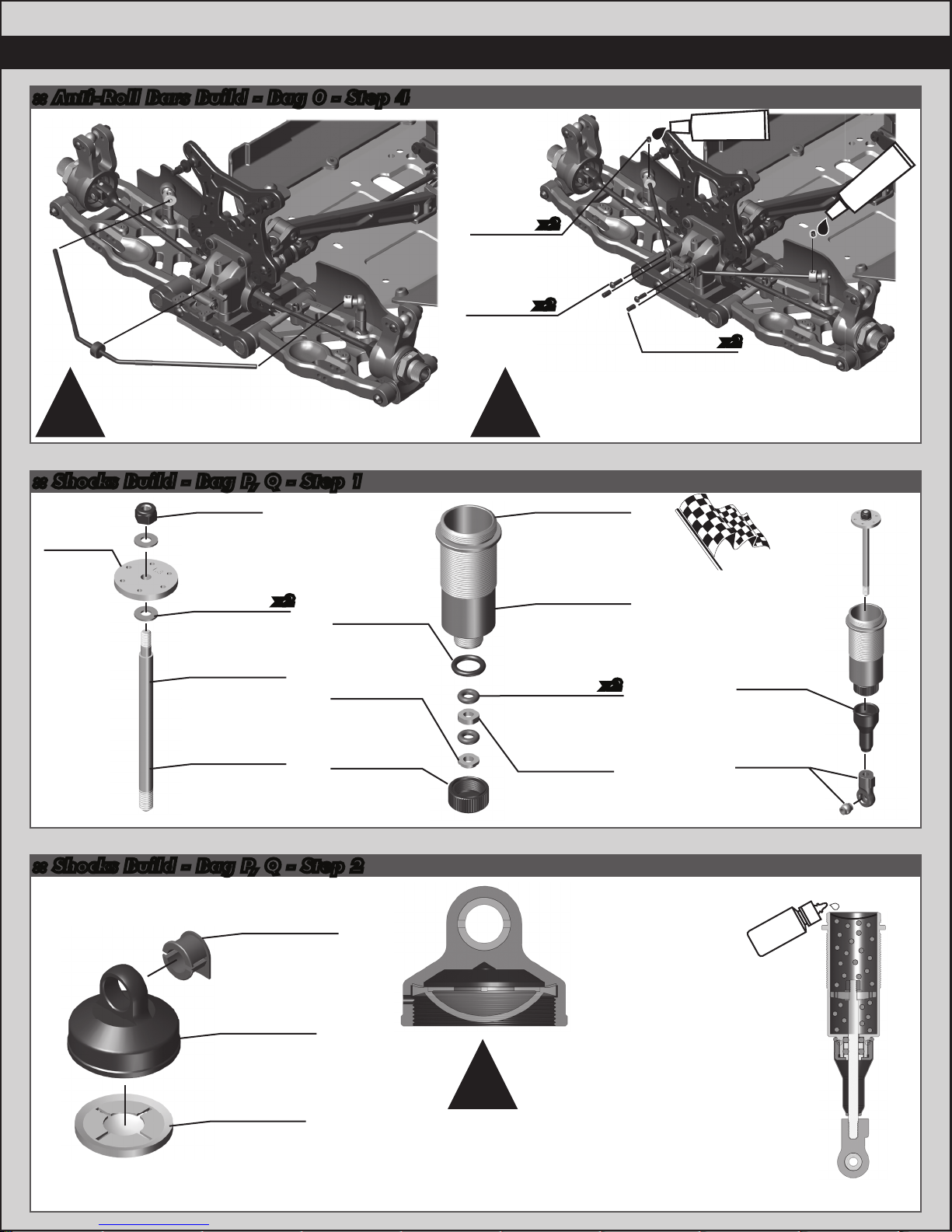
:: Shocks Build - Bag P, Q - Step 2
:: Shocks Build - Bag P, Q - Step 1
:: Anti-Roll Bars Build - Bag 0 - Step 4
When installing the
shock bladder, make
sure it is correctly
seated within the
shock cap as shown.
!
81186
Shock
O-Ring
81185
O-Ring Hat
Bushing
81188
Shock Body
Seal
Retainer
81193
Shock
Rod End
and Ball
81190
Shock
Boots
81200
Shock
Piston
(6x1.3
flat)
25225
3x3mm
Set Screw
31521
2.5x8mm
BHCS
x2
x2
x2
81170
Shock Shaft,
30.5mm
(Front)
81185
O-Ring
Spacer
81160
Shock Body,
30.5mm
(Front)
81161
Shock Body,
39.5mm
(Rear)
81185
Shock Body
O-Ring
81171
Shock Shaft,
39.5mm
(Rear)
81181
Shock Cap
Insert
81180
Shock Cap
81182
Shock
Bladder
89278
2.5mm
Washer
89215
Shock
Piston
Locknut
81257
3x6mm
Set Screw
x2
x2
Tighten #81257 set screws
just enough to still allow the
anti-roll bar to move freely.
!!
shock
fluid
Front Shock Fluid:
37.5wt #5433
Rear Shock Fluid:
30wt #5422
#1596
thread lock
#1596
thread lock
Racer’s Tip:
Use shock fluid
or green slime
(#1105) to
lube the O-Rings
before installation!
Rear Hub Turnbuckles
removed for view clarity.

19
:: Shocks Build - Bag P, Q - Step 5
:: Shocks Build - Bag P, Q - Step 4
:: Shocks Build - Bag P, Q - Step 3
Some residual shock
fluid may appear from
your first few runs
around the shock cap
as a result of bleeding.
Leave a gap when
installing the shock cap.
Compress shock shaft half way.
Let shock fluid bleed from cap, then
tighten cap.
For less rebound, compress shock
shaft farther before tightening the
shock cap.
For more rebound, do not
compress shock shaft as far
before tightening the shock cap.
!
!!
81193
Spring
Cup
81185
Shock Spring
Collar O-Ring
81183
Shock Spring
Collar
81214
Front Spring,
Blue (5.0lb/in)
81219
Rear Spring,
Blue (4.3lb/in)
The shock springs
come with colored
heat shrink tubing.
Install them on the
springs for easy
identification.
!
shock
fluid
25612
M3 Locknut
W/ Flange
81197
Shock
Pin
81257
3x6mm
Set Screw
Kit Setup:
Mount the rear shock in the
outside hole on the rear arm.
25612
M3 Locknut
W/ Flange
81197
Shock
Pin
81257
3x6mm
Set Screw
Kit Setup:
Mount the front shock in the
outside hole on the front arm.

20
:: Battery Tray Build - Bag R - Step 3
:: Battery Tray Build - Bag R - Step 2
:: Battery Tray Build - Bag R - Step 1
81262
4x10mm
FHCS
81263
4x16mm
FHCS
81298
RC8B3e
Battery Foam
81297
RC8B3e
Battery Tray
x3
x2
x2
Battery
not
included!
Install the ESC wire as shown first.
Then run the hook and loop straps
as shown.
!
89506
Hook and Loop
Battery Strap
6727
Servo
Tape
x2
ESC not
included!
Table of contents
Other AE Motorized Toy Car manuals


Popular Motorized Toy Car manuals by other brands

Supertrax
Supertrax Rancher Installation and operation instructions

REVELL
REVELL KIT 2016 Assembly manual

Serpent Model Racing Cars BV
Serpent Model Racing Cars BV SPYDER SRX2 MH instruction manual

Maverick
Maverick SCOUT RC instruction manual

SunFounder
SunFounder Smart Car Kit V2.0 manual

HPI Racing
HPI Racing WHEELY KING instruction manual


