SunFounder Smart Car Kit V2.0 User manual

Preface
About SunFounder
SunFounder is a technology company focused on Raspberry Pi and Arduino open source
community development. Committed to the promotion of open source culture, we strive to
bring the fun of electronics making to people all around the world and enable everyone to
be a maker. Our products include learning kits, development boards, robots, sensor modules
and development tools. In addition to high quality products, SunFounder also offers video
tutorials to help you build your own project. If you have interest in open source or making
something cool, welcome to join us! Visit www.sunfounder.com for more!
About the Smart Car Kit V2.0 for Arduino
This smart car can go forward and backward, and turn left and right. Controlled by the
SunFounder Uno board, it can realize IR remote control, line following, hand following,
obstacle avoiding, etc.
This car kit is a great platform for you to get started with robotics. After assembling the car
based on the instructions in this booklet, you will learn how to operate the smart car through
6 experiments corresponding to the aforementioned movements. Furthermore, you can
extend more functions or build your own robot based on what's learnt.
Note:
Go to LEARN -> Get Tutorials -> Smart Car Kit V2.0 for Arduino on our website
www.sunfounder.com to view the related code and other materials. Please read this manual
carefully before experiment. You are suggested to follow this guide to assemble the smart
car model and carry out each experiment taking the wiring steps with diagrams. Then, with
the knowledge needed, you may be able to DIY another car!
Free Support
If you have any TECHNICAL questions, add a topic under FORUM section on our
website and we’ll reply as soon as possible.
For NON-TECH questions like order and shipment issues, please send an email to
service@sunfounder.com. You’re also welcomed to share your projects on FORUM.
SunFounder

Contents
Components List ..................................................................................................................... 1
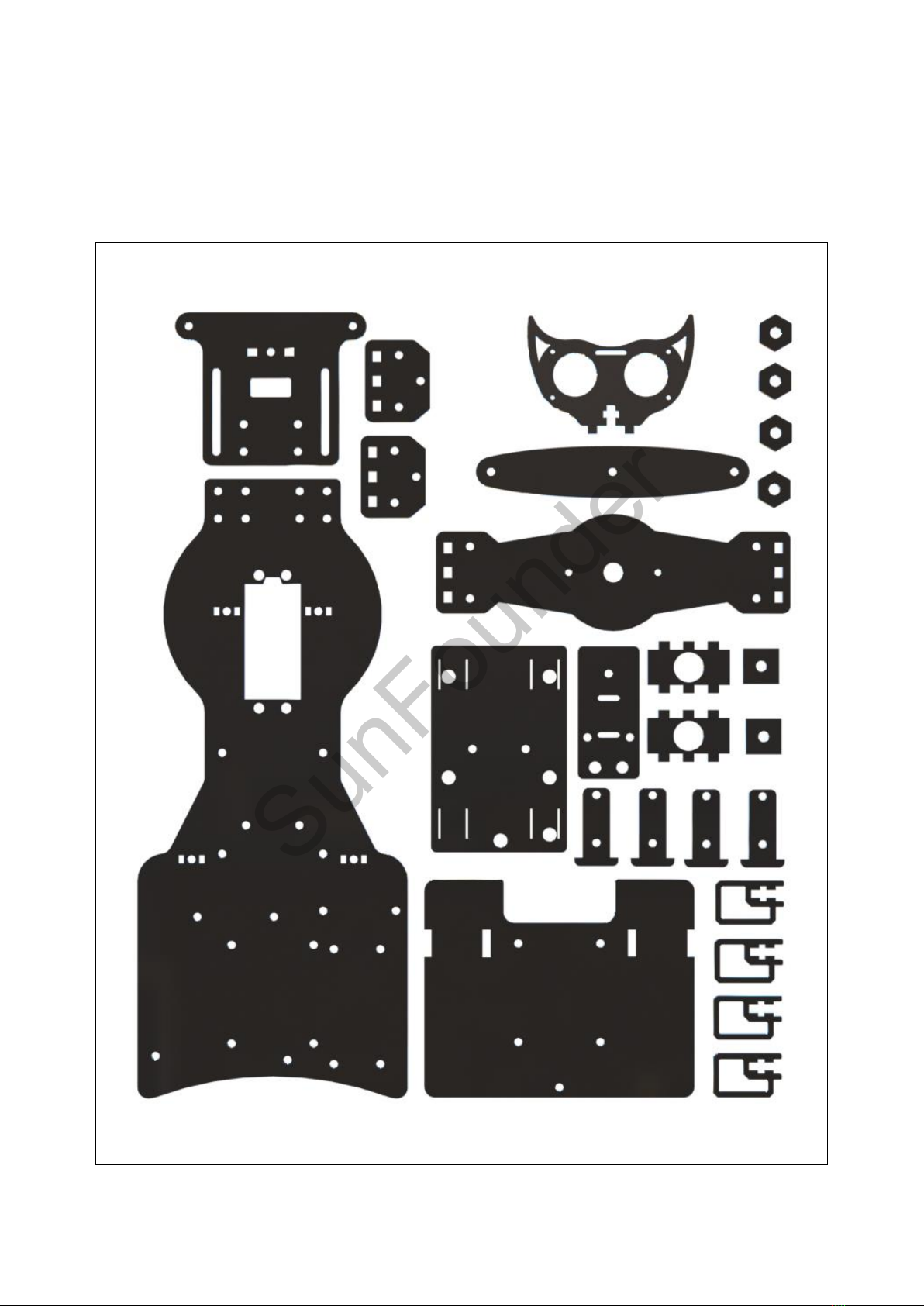
Acrylic Plate ...................................................................................................................... 1
Mechanical Fasteners ..................................................................................................... 2
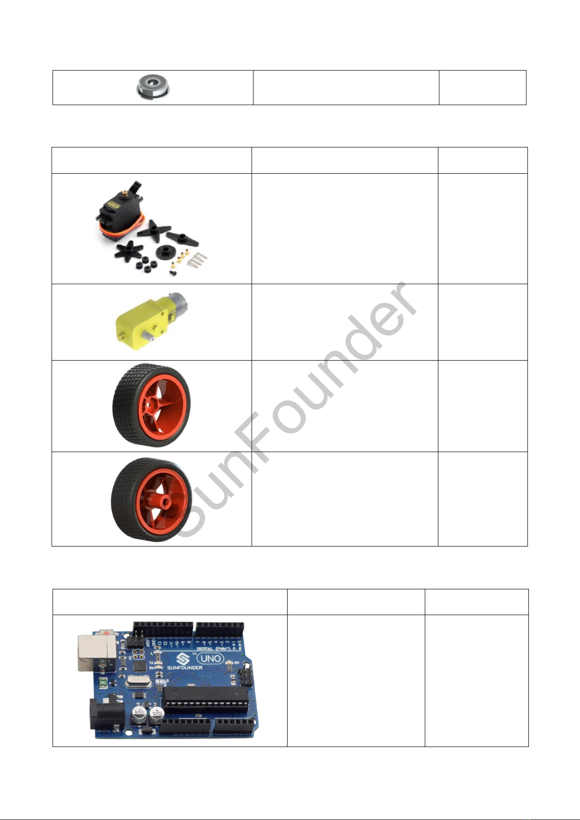
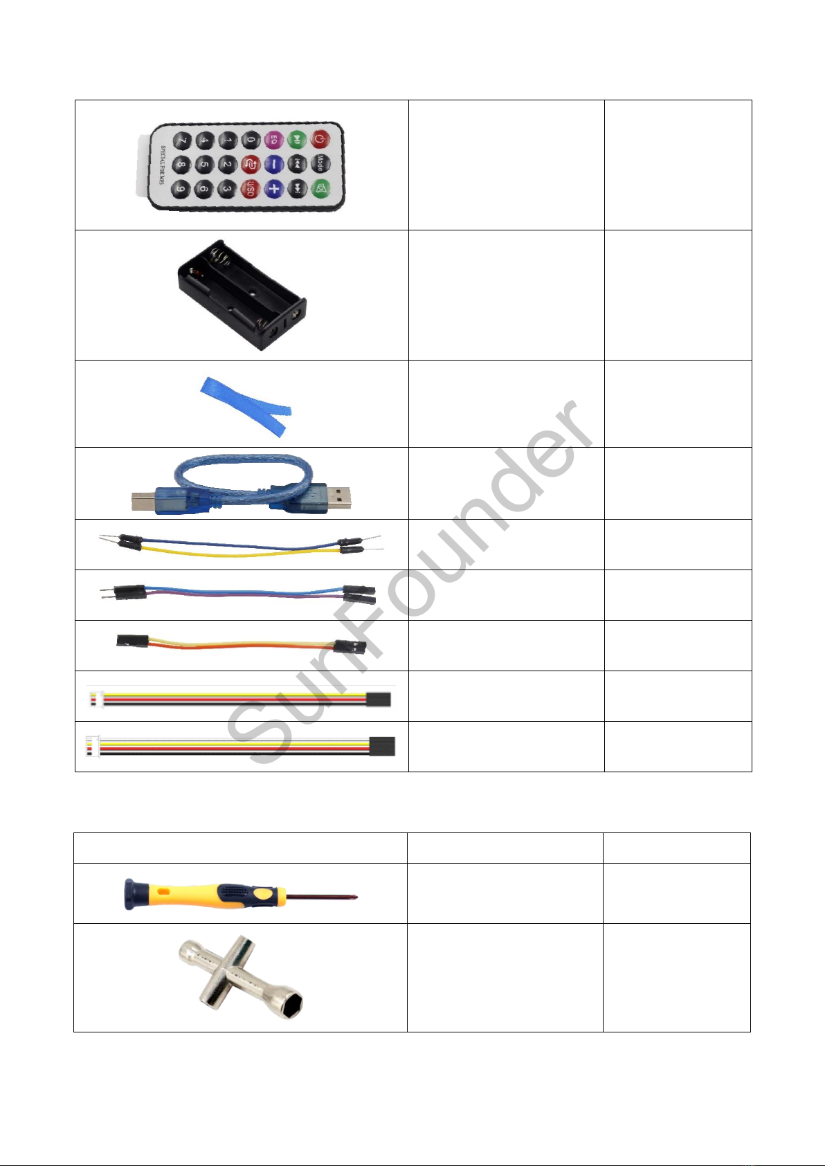
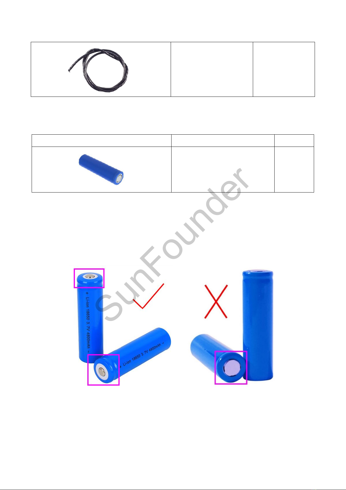
Power Accessories ........................................................................................................... 3
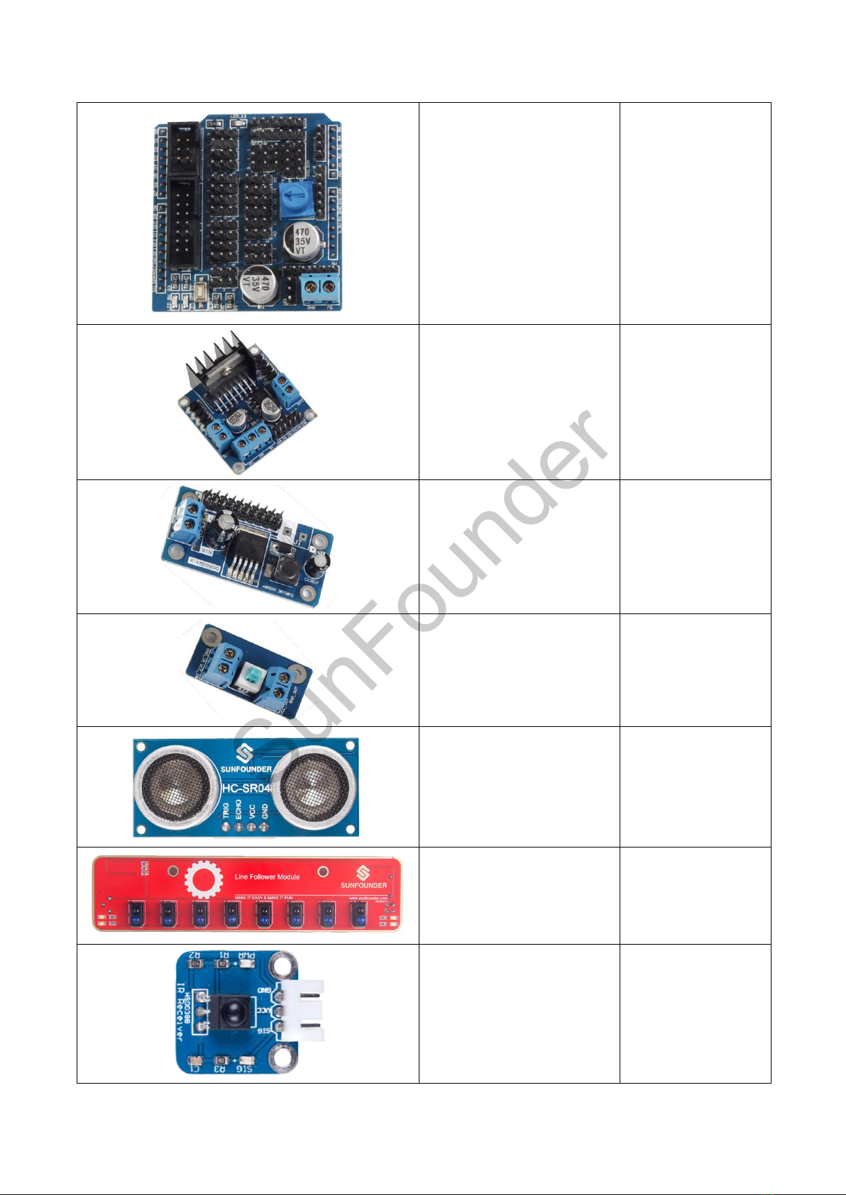
Electronic Accessories..................................................................................................... 3
Tools.................................................................................................................................... 5
Self-provided Components ............................................................................................ 6
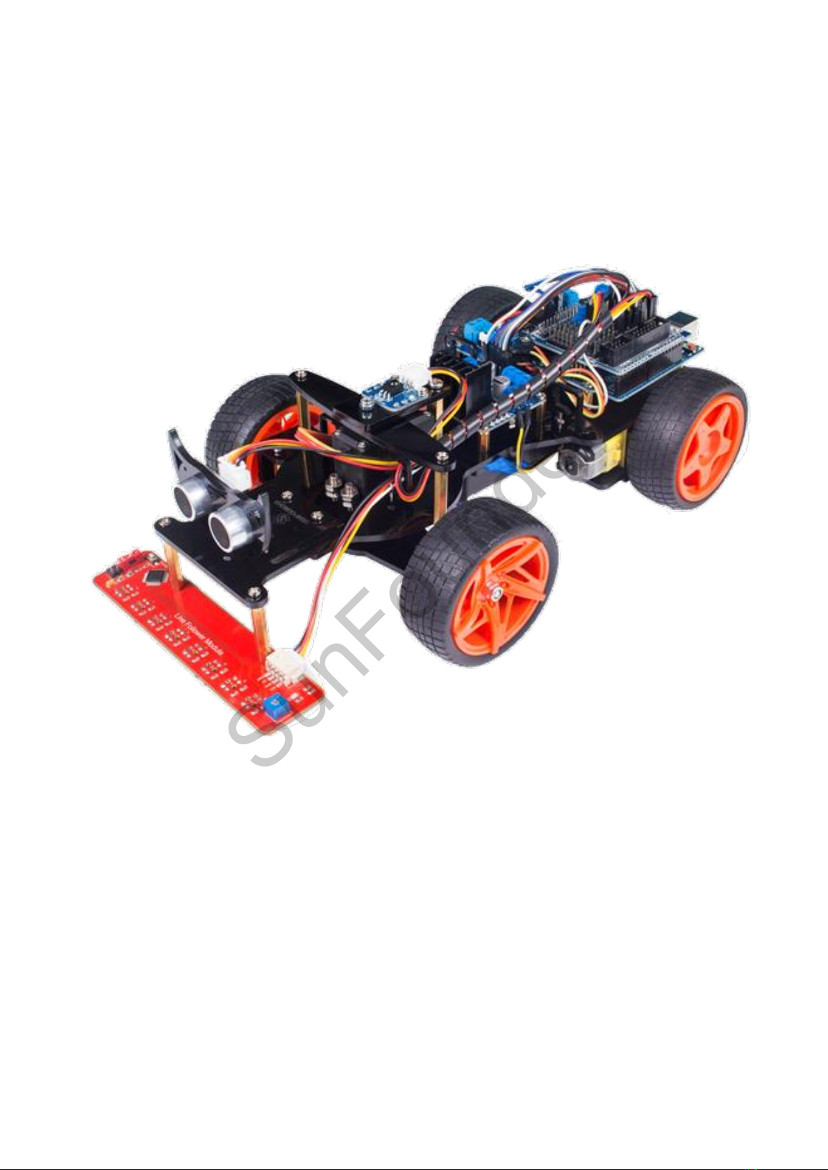
Introduction to the Smart Car V2.0 for Arduino................................................................. 7
Get Started .............................................................................................................................. 8
Arduino .............................................................................................................................. 8
Description.................................................................................................................. 8
Arduino Board –SunFounder Compatible ............................................................ 8
Install Arduino IDE ...................................................................................................... 9
Add Libraries............................................................................................................. 12
Sensor Shield ................................................................................................................... 13
Motor Driver Module...................................................................................................... 15
Step-down DC-DC Converter Module ....................................................................... 17
Switch Module ................................................................................................................ 19
Ultrasonic Module HC-SR04 Distance Sensor............................................................. 20
Line Follower Module..................................................................................................... 21
IR Receiver Module........................................................................................................ 22
Servo................................................................................................................................. 22
Car Assembly ........................................................................................................................ 24
Front Wheels.................................................................................................................... 24
Deflecting Plate + Front Wheels................................................................................... 25
Deflecting Plate + Rocker Arm .................................................................................... 26
Rear Lower Plate + Rear Wheels.................................................................................. 27
Deflecting Top Plate ...................................................................................................... 29
SunFounder

Servo + Chassis + Battery Holder.................................................................................. 30
Adjust the Servo.............................................................................................................. 34
Chassis + Deflecting Plate ............................................................................................ 36
Chassis + Driven Wheels ................................................................................................ 37
IR Receiver + Ultrasonic + Line Follower...................................................................... 40
Other PCB Assembly ...................................................................................................... 41
Circuit Building................................................................................................................ 42
Experiments ........................................................................................................................... 50
Experiment 1 Going Forward and Backward ............................................................ 50
Experiment 2 Turning Right and Left............................................................................ 50
Experiment 3 IR Remote Control.................................................................................. 51
Experiment 4 Line Following ......................................................................................... 52
Experiment 5 Hand Tracking ........................................................................................ 54
Experiment 6 Obstacle Avoidance............................................................................. 54
SunFounder

1
Components List
Acrylic Plate
SunFounder

2
Mechanical Fasteners
Component
Name
Qty.
M1.5*8 Screw
6
M3*12 Countersunk Screw
4
M3*6 Screw
18
M3*8 Screw
40
M3*10 Screw
10
M3*28 Screw
6
M4*10 Screw
8
M4*20 Screw
4
M3*10 Copper Standoff
16
M3*13 Copper Standoff
6
M3*25 Copper Standoff
6
M3*30 Copper Standoff
4
M3*35 Copper Standoff
4
M4*30 Copper Standoff
4
M1.6 Nut
6
M3 Nut
17
M4 Nut
4
M3 Self-locking Nut
2
M4 Self-locking Nut
4
SunFounder

3
F694ZZ Flange Bearing
4
Power Accessories
Component
Name
Qty.
Tower Pro MG995 Micro Servo
1
Gear Motor
2
Driven Wheel
2
Driving Wheel
2
Electronic Accessories
Component
Name
Qty.
SunFounder Uno
1
SunFounder

4
Sensor Shield
1
DC Motor Driver Module
1
Step-down DC-DC
Converter Module
1
Switch Module
1
HC-SR04 Ultrasonic
Module
1
Line Follower Module
1
IR Receiver Module
1
SunFounder

5
IR Remote Controller
1
18650x2 Battery Holder
1
Ribbon (13cm)
2
USB Data Cable (1m)
1
12cm Male-to-Male
Jumper Wire
6
10cm Male-to-Female
Jumper Wire
2
10cm Female-to-Female
Jumper Wire
10
25cm 3-pin Anti-reverse
Cable
1
25cm 4-pin Anti-reverse
Cable
2
Tools
Component
Name
Qty.
Cross Screwdriver
1
Cross Socket Wrench
1
SunFounder

6
Heat Shrink Tube
1
Self-provided Components
The following components are not included in this kit.
Component
Name
Qty.
18650 3.7V Rechargeable Li-
ion Battery
2
Note:
1. You are recommend to use 18650 batteries without a protective board. Otherwise, the
car may be cut power and stop running because of the overcurrent protection of the
protective board.
2. For unprotected batteries, please purchase those with the anode bulged out (as shown
below), so that it can ensure the well connection with the battery holder.
3. If you only have batteries with the protected board, it’s ok. To use it, you can remove the
board on the cathode. But you should operate with care to avoid any hurt; Since the
metal shell is connected to the cathode for most batteries, please don’t use screw driver
or other metal objects to remove, or the battery may get shorted and be burnt if the shell
is connected to the positive pole accidentally.
SunFounder

7
Introduction to the Smart Car V2.0 for Arduino
The smart car is a great platform for you to get started with robotics. According to the
instructions in this manual, you will learn not only how to assemble a robot car but also play
the smart car through 6 experiments. After mastering every experiment, you can extend its
functions or build your own platform based on our smart car platform.
With the modules and sensors added, the smart car can go forward, go backward, and turn
left and right. Besides, it can realize IR remote control, line following, hand tracking, obstacle
avoidance, etc. Many boards and sensors are used in this project such as the sensor shield,
motor driver module, step-down DC-DC converter module, switch module, ultrasonic
ranging module, photosensitive module, obstacle avoidance module, and line follower
module. Different modules are used to achieve corresponding functions. And the car is
controlled by SunFounder Uno board. Next let's first check these modules in detail.
SunFounder

8
Get Started
Note:
Before starting your own project, you must download the Smart_Car_V2.0_for_Arduino.zip
package on our website by visiting LEARN -> Get Tutorials -> Smart Car Kit V2.0 for Arduino
and unzip it.
Arduino
Description
Arduino is an open source platform that applies simple software and hardware. You can get
it in a short even when you know little of it. It provides an integrated development
environment (IDE) for code editing and compiling, compatible with multiple control boards.
So you can just download the Arduino IDE, upload the sketches (i.e. the code files) to the
board, and then you can see experimental phenomena. For more information, refer to
http://www.arduino.cc.
Arduino Board –SunFounder Compatible
In this kit, the SunFounder Uno R3 board is used and it is completely compatible with Arduino
Uno Board.
SunFounder

9
Install Arduino IDE
The code in this kit is made based on Arduino, so you need to install the IDE first. Skip it if you
have done this.
Step 1: Go to the arduino.cc website and click Software. On the page, check the software
list on the right side under Download the Arduino Software.
Find the one that suits your operation system and click to download. There are two versions
of Arduino for Windows: Installer or ZIP file. You're recommended to download the former.
Step 2: Double click the .exe file and the following window will show up. Click I Agree. The
following interface will show up.
SunFounder

10
Next.
Click Browse to choose the installation path or enter a directory at the Destination Folder.
Click Install.
The following interface will show up. (After the installing progress bar goes to the end, the
Close button may be enabled for some PC. Just click it to complete the installation.)
SunFounder

11
Then a prompt appears. Select Always trust software for "Adafruit Industries" and click Install.
Select Always trust software for "Arduino srl" and click Install.
After the installation is done, click Close. Then an Arduino icon will appear on the desktop:
SunFounder

12
Add Libraries
1) Select Sketch -> Include Library -> Add ZIP Library.
2) Find the file MsTimer2.zip under Smart Car V2.0 for Arduino\Code\Library. Click Open.
3) Similarly, add IRromte.zip and NewPing.zip under Smart Car V2.0 for
Arduino\Code\Library to library.
4) Then you'll be prompted by Library added to your libraries. Check "Import libraries". You
also can see the libraries just imported have appeared on the list by going to
Sketch->Include Library->MsTimer2.
SunFounder

13
Sensor Shield
It is convenient to place components on a breadboard. However, you need to have some
electronic foundation to build various kinds of circuit. By using this sensor shield, you only need
to wire components to the shield with some jumper wires, and then you can build your own
project quickly. The sensor shield is one of the most common Arduino peripheral devices, as
shown below:
SunFounder

14
Its schematic diagram is as shown below: note that VCC only supplies power to the devices
connected to D2 (hooked to the black servo) and D3. Other components are powered by
5V.
SunFounder

15
Motor Driver Module
The motor driver module is used to drive two motors to rotate. The driver chip used here is
L298N.
Its schematic diagram is as shown below:
SunFounder

16
L298N is a high voltage, large current driver chip manufactured by ST, which uses a 15-pin
package.
Its main features are as follows:
• High operating voltage, which can be up to 40 volts.
• Large output current - the instantaneous peak current can be up to 3A.
• With 25W rated power.
• Two built-in H-bridge, high voltage, large current, full bridge driver, which can be used to
drive DC motors, stepper motors, relay coils and other inductive loads.
• Using standard logic level signal to control.
• Able to drive a two-phase or four-phase stepper motor, and two-phase DC motors.
Its pin functions are as shown below:
Pin
Name
Description
1
15
Sense A
Sense B
The sense resistor is connected between this pin and ground to
control the current of the load.
2
3
Out 1
Out 2
Outputs of the Bridge A; the current that flows through the load
connected between these two pins is monitored at pin 1.
4
Vs
Supply Voltage for the Power Output Stages.
A non-inductive 100nF capacitor must be connected between this
pin and ground.
5
7
Input1
Input2
TTL Compatible Inputs of the Bridge A.
6
11
Enable A
Enable B
TTL Compatible Enable Input: the L state disables the bridge A
(enable A) and/or the bridge B (enable B).
8
GND
GND
9
Vss
Supply Voltage for the Logic Blocks. A100nF capacitor must be
connected between this pin and ground.
10
12
Input3
Input4
TTL Compatible Inputs of the Bridge B.
13
14
Out 3
Out 4
Outputs of the Bridge B. The current that flows through the load
connected between these two pins is monitored at pin 15.
SunFounder

17
The driver module can drive two motors. The enable terminals ENA and ENB are effective at
high level. The control mode (high/low level) and state of motor A are as shown below:
ENA
IN1
IN2
State of Motor A
0
X
X
Stop
1
0
0
Brake
1
0
1
Rotate clockwise
1
1
0
Rotate counterclockwise
1
1
1
Brake
If you want to regulate the speed of motor A by PWM, you need to set IN1 and IN2, confirm
the rotational direction of the motor, and then output PWM pulses for enabled terminals.
Please note that the motor is in the free stop state when the signal of enabled terminal is 0.
When the enabled signal is 1, if IN1 and IN2 are 00 or 11, the motor is in brake state, and the
motor stops rotating. If IN1 is 0 and IN2 is 1, the motor A rotates clockwise; if IN1 is 1 and IN2 is
0, the motor A rotates counterclockwise. This is the control method for motor A. The control
method for motor B is the same as that for motor A.
Step-down DC-DC Converter Module
The DC-DC module is used to reduce the input voltage and output a stable 5 volts voltage.
Here the LM2596 switching voltage regulator is used to regulate the voltage.
SunFounder
Table of contents
Other SunFounder Motorized Toy Car manuals