manuals.online logo
Brands
  1. Home
  2. •
  3. Brands
  4. •
  5. Ofna Racing
  6. •
  7. Motorized Toy Car
  8. •
  9. Ofna Racing CD-3 SPORT RTR User manual

Ofna Racing CD-3 SPORT RTR User manual

CD-3 SPORT RTR and PRO RTR
ASSEMBLY INSTRUCTIONS
ASSEMBLY OF THE DIFFERENTIAL
(Build two differentials for front and rear.)
2.5mm
E-Ring 5x8x1.5mm
O-Ring 5x10mm
Washer Diff.Gear
(small) Diff.Gear
(Large)) 10x15x4mm
Bearing 3x17.8mm
Pin
Flat Head
Screw
M2x7mm
Put the grease
into the diff.
case before
assembly.
10x15x4mm
Ball Bearing
Diff.Case
2.5mm
E-Ring
38256
38252
38253
37450
37771 5x10mm
10T Diff.Gear
10T Diff.Gear
(small)
(small)
13T
Diff.Gear
Step 1
Step 3 Step 4
Step 2
3x17.8mm
Pin
38287
Diff.Gasket
Flat Head
Screw
M2x7mm
Cap Joint
Cap Joint
10x15x4mm
Ball Bearing
2.5mm
E-Ring
5x8x1.5mm
O-Ring
5x8x1.5mm
O-Ring
38278
38255
38255
38257
37450
5x10mm
Washer
13T
Diff.Gear(Large)
Large
Bevel Gear
94052 38278 38256 37771 37450 38253
37771
38278
38256
94052
90020 38632
38632 90020
90020
38632
Washer
M3X12mm
M3X12mm
Screw
Screw For Front
For Rear
2.6x10mm
Hex Screw
2.6x10mm
Hex Screw
2.6x10mm
Hex Screw
Gear Case
Gear Case
38251
38251
ASSEMBLY OF THE FRONT GEAR BOX
(Builds a gear box for the front.)
* The picture shown is the gear box after
assembly.
* It is normal for the gears to make a noise.
After brake-in, the noise will be reduced.
* Note: Do not over tighten the
2.6x10mm hex screw as it
may cause damage to the
hole in plastic.
94050 94004
94004 94050
ASSEMBLY OF THE GEAR BOX
(Build two gear box for front and rear.)
2.5mm
E-Ring
2.5mm
E-Ring
38258
38526
38519
37400
38251
5x8x0.8mm
Washer
37430
5x11x4mm
5x11x4mm
Ball Bearing
Ball Bearing
M3x4mm
Screw
38530
Steel Ring
(For Front Plastic
Cap Joint)
2x8.8mm
Pin
Gear case 16T Bevel Gear
(small)
38258
16T Bevel Gear
(small)
Bevel Gear
Shaft (small)
38526
Bevel Gear
Shaft (small)
Bevel Gear
Cap Joint (F)
*Adjust the backlash
with the shim*
* Put the gear in the
right position.
* For the good gear mesh,
put the 5x8x0.8 washer
between L-06 and E-43.
Note: Follow the instruction
to put the correct shim
in the right place.
38254
12x15x0.25mm
Shim
37340
5x11x4mm
Ball Bearing
¡¯CHECKI NGYOURDI FFERENTI ALASSEMBLY
To test the effectiveness of the gear
differential, hold the gear tightly with one
hand and turn one cap joint.
Does the other cap joint move in the
opposite direction and smoothly?
If gear differential does not move smoothly,
assemble the gear diff. once again.
38519
Bevel Gear
Cap Joint (R)
37430
94001
38633
90020
90020
ASSEMBLY OF 2-SPEED CLUTCH TRIGGER DISC
SCREW AS SHOWN,
LEVEL WITH HOLE EDGE
SCREW AS SHOWN,
LEVEL WITH HOLE EDGE
SET BALLTO REST ON CAM, NOT PUSHING. IF
TOO TIGHT, THE BALL WILL PUSH ON CAM
SPREADING SHOE DISC AND WILL NOT FIT
INTOALUM. CLUTCH BELL #38296
CARE MUST BE TAKEN TO BUILD
THIS ASSEMBLY CORRECTLY,
OTHERWISE 2-SPEED WILL NOT
ADJUST AND MAY NOT WORK AT ALL.
IN FACT, IF 2-SPEED DOES NOT
SHIFT, CHECK OUT THIS ASSEMBLY!.
38525
38316
38313
38313
38313
38312
38312
38315
38315
ASSEMBLY OF THE TWO SPEED CLUTCH SHOES
4x4mm
Set Screw 3x3mm
Set Screw
3x3mm
Set Screw
3x3mm
Set Screw
4x4mm
Set Screw
Clutch Shoe
Carrier
2 Speed Main Shaft
(Cd3 only)
Spring
Spring
Spring
M2x10mm
Hex Screw
M2x10mm
Hex Screw
M2x10mm
Hex Screw
Steel Ball
Steell Ball
2 Speed
Clutch Shoe
2 Speed
Clutch Shoe
* Slide the Clutch Shoe Carrier
over the 38525 and set the
4x4 screw in the "D" cut.
Step 2
Step 1
35325
94033
35325
94034
94033
94034
94033
37430
37430
38519
38519
38279
38279
40042
38519
37400
37400
M3x4mm
M3x4mm
Screw
screw
2x8.8mm
2x8.8mm
Pin
Pin
3x13.8mm
Pin
Pin
38279
M3x4mm
screw 2x8.8mm
Pin 3x13.8mm
Pin
37430
5x11x4mm
Ball Bearing
5x11x4mm
5x11x4mm
6x18.5x4mm
Bevel Gear
Ball Bearing
Ball Bearing
Plastic Washer
Cap Joint(R)
Brake Disk
Brake Disc
Mount
* Put the brake disk
before assembly
*Insert the 38279 into Break
disc mount.
ASSEMBLY OF THE TWO SPEED GEAR
38T
38300
38295
38296
38297
Spur Gear
38301
Spur Gear 1 st Gear Carrier
(One-Way)
2nd Gear
Clutch Bell
(Ball Bearing)
Retaining Ring
Retaining Ring
* Trim any burrs from the
inside of the edge with
a hobby knife before
assembly.
Step 1
Step 2
ASSEMBLY OF THE BRAKE AND DIFF. MOUNT
M3x12mm
M3x30mm
Screw
Screw M2x8mm
Hex Screw
Brake
Spring
Remove the double-side
tape before assembly.
M3x12mm
M3x30mm
M3x30mm
Screw
Screw
Screw
M2x8mm
Hex Screw
38519
38519
38273
38520
38520
38520
40040
Plastic Bushing
Brake Cam
Blake Pad
Spring
Brake Mount
(Upper)(Front)
Roll Bar
Brake Mount
(Upper)(Rear)
* Position the brake cam
in the direction as shown.
Please notice!
* Leave the 1.5mm space
between brake pads.
1.5mm
Bushing Support
Brake Pad
Linings
Brake Pad
3x13.8mm
38297
94001
94001
37400
94001
38272
38271
94004
94047
94004
94047
40040
94000
94000
94000
*"L" make are for
left-side.
ASSEMBLY OF THE FRONT KNUCKLE ARMS AND CVD SHAFT
10mm Alum.
Set Screw
10mm Alum.
Set Screw
10mm Alum.
Set Screw
Front Knuckle
Arm (Left)
Front Knuckle
Arm (Right)
5x11x4mm
Ball Bearing
5x11x4mm
Ball Bearing
5x11x4mm
Ball Bearing
10x15x4mm
Ball Bearing
10x15x4mm
Ball Bearing 8mm
Steering Ball
8mm
Steering Ball
8mm
Steering Ball
8mm
Steering Ball
Washer
8mm
Steering Ball
Washer
39150
38265
37430
39140
39140
39141
Make steering
ball move
smooth.
Make steering
ball move
smooth.
Assembly of the right and left-side are the same.
Push 2 ball
bearings into
knuckle arm
as shown.
*Notice the direction
of the hex screw.
Step 1
Step 3
Step 2
2x9.8mm
Pin
CVA Dog Bone
38524
38523
CVD Shaft
ASSEMBLY OF THE FRONT SUSPENSION ARMS Assembly of the right and left-side are the same.
3x8 mm
Set Screw
3x8 mm
Set Screw
3x8 mm
Set Screw
38399 RIGHT SIDE
38399
38399
38399
37360
37360
Front Upper
Arm
Front Upper Arm
Front Lower
Arm
Front Lower Arm
4mm
4mm Ball&Socket
Ball&Socket
FRONT KNUCKLE
ARM ASSEMBLY.
FRONT KNUCKLE
ARM ASSEMBLY.
3 x 8mm set screw is
used to adjust the
ride height.
A 3 x 8mm set screw
is used to adjust the
ride height.
LEFT SIDE
39150 37430 37450 39140
37450
38406
39150
39141
37430
38265
94035
94035
94035
ASSEMBLY OF THE REAR SUSPENSION ARMS
3x8 mm
Set Screw
3x8 mm
Set Screw
Ball & Socket
37360
Ball & Socket
Ball & Socket
M3x16 mm
Screw
M3x16 mm
Screw
6 mm
Ball & Socket
6 mm
Ball & Socket
Rear Upper Arm
38399
38398
37370
37370
3x20mm
3x20mm
Turnbuckle
Turnbuckle
(Right- Hand Side)
9 mm
38399
Rear Lower Arm
Rear Lower Arm
A 3 x 8mm set screw is used
to adjust the ride height.
3x8 mm
Set Screw M3x16 mm
Screw
6 mm
Ball & Socket
38399
38399
38399
37370
Upper Arm
Plastic Rod End
Upper Arm
Plastic Rod End
Rear Upper Arm
Rear Upper Arm
(Left- Hand Side)
A 3 x 8mm set screw is used
to adjust the ride height.
Push 2 ball bearings into
rear wheel hub as shown.
ASSEMBLY OF THE REAR WHEEL HUB
10mm Alum.
Set Screw
10mm Alum.
Set Screw
10mm Alum.
Set Screw
5x11x4mm
Ball Bearing
5x11x4mm
Ball Bearing
10x15x4mm
Ball Bearing
Rear Wheel
Hub
8mm
Steering Ball
Washer
8mm
Steering Ball
Washer
39150
37430
37430
38266
38267
37450
39141
39141
Rear Wheel
Axle Shaft
Notice the direction
of the steering ball
washer.
Assembly of the right and left-side are the same.
Push
10x15x4mm
Ball Bearing
8mm
Steering Ball
Push
39150
39150
37450
39140
94005
38399
94035
37360
94005
94035
38399
37360
94035
94005
M3
Nylon Nut
38288
38289
Servo Saver
38289
Servo Saver
38289
Servo Saver
38289
Servo Saver
38644
35958
35958
36742
37360
4mm
Ball & Socket
37360
4mm
Ball & Socket
37360
4mm
Ball & Socket
M3x12mm
Screw
M3x12mm
Screw
M3x12mm
Screw
Servo Saver
Spring
Servo Saver
Bushing
3x6x2.5mm
Brass Bushing
3x6x2.5mm
Brass Bushing
5x8x2.5 mm
Brass Bushing
5x8x2.5 mm
Brass
Bushing
ASSEMBLY OF THE SEVRO SAVER
M3
Nylon Nut 38281
38276
38277
36742
4mm
Ball & Socket
3x40mm
Turnbuckle
37650
4mm
Ball End (Long)
37650
4mm
Ball End (Long)
M3x10mm
Screw
M3x12mm
Screw
Servo Saver
Spring
Servo Saver
Bushing
3x6 mm
Brass Bushing
5x8 mm
Brass Bushing
A
B
A
A
B
Made two steering rod for left and
right hand side.
Put steering rod into
4mm ball & socket.
Put steering rod into
4mm ball & socket.
Snap steering rod into
4mm ball & socket.
*Use the long ball end for both steering rod and steering servo rod.
Steering Rod
3x6x2.5m
Ballbearing x2
5x8x2.5mm
Ballbearing x2
38644 Ballbearing Set
(For servo Saver )
Option:
Approx 57 mm
38281
37650
4mm
Ball End (Long) 3x36mm
Turnbuckle
37650
4mm
Ball End
(Long)
Steering Servo Rod
Approx 54 mm
ASSEMBLY OF THE SEVRO SAVER
AND STEERING RODS
M3
M3
38275
38528
Nylon Nut
Nylon Nut
M3x10mm
Flat Head
HexScrew
M3x10mm
Flat Head
HexScrew
M3x5mm
Flat Head
Hex Screw
Servo saver
Screw
Cd3 Stock
Chassis
M3
Nylon Nut
M3x5mm
Flat Head
Hex Screw
38275
Servo saver
Screw
M3x10mm
Flat Head
HexScrew
Front Gear
Box Assembly.
Arm Holder for 0
(Lower/Rear)
cS rewCement
35958
38288
94004
94003
37360
94041
94041
94004
94004
94004
38263
94041
94041
94019
94018
94018
94041
38644
94019 94019
ASSEMBLY OF THE FRONT ARM HOLDER
ONTO CHASSIS
ASSEMBLY OF THE FRONT STABILIZER
38263
Lower Arm Holder for 0 and 1.5 and
2.5 degree.
38419
38263
M3x3mm
M3x3mm
M3x10mm
Flat Head
HexScrew
For assembly stabilizer:
37360
4mm
Ball & Socket
3X55mm
Lower Arm Shaft
M3x10mm
Flat Head
Hex Screw
M3x16mm
Screw
2.5mm
E-Ring
M3x3mm
Set Screw
4mm
Ball & Socket
38419
3x55mm
Lower Arm Shaft
38418
M3x16mm
M3x16mm
M3x3mm
M3x3mm
Assembly of front stabilizer 2.5mm
2.5mm
Stabilizer
Mount
Screw
Screw
Set Screw Set Screw
E-Ring
E-Ring
Stabilizer
Mount *Turn stabilizer balance adjuster to
adjust the stabilizer to the same angle.
*Keep stabilizer ball in the center.
Stabilizer
Stabilizer
Balance
Adjuster
Arm Holder
(Front/Lower)
Insert the drive shaft
before assembly.
Assembly of the right and left-side are the same.
Use the 0 degree for
front arm holder. *Put steering rod into
4mm ball & socket
..
* Use a 3mm drill to
hone out the front
lower arm holder.
Center
94033
94019
37360
94005
94033
94005
94033 38420 94033
94005
38418
94019
90020
90020
90020
38518
2.5mm
E-Ring
M3X3mm
Set Screw
M3X16mm
Screw
M3x3mm
Set screw
M3x3mm
Set screw
M3x16mm
Screw
M3x16mm
Screw
90020
2.5mm
E-Ring
90020
2.5mm
E-Ring
38420
stabilizer
38418
Stabilizer
Mount
38418
Stabilizer
Mount
38418
Stabilizer
Balance
Adjuster
ASSEMBLY OF THE REAR STABILZER
Assembly of rear stabilizer
*Keep stabilizer ball in the center.
*Turn stabilizer balance adjuster to
adjust the stabilizer to the same angle.
ASSEMBLY OF THE FRONT STIFFENER
ONTO CHASSIS ASSEMBLY OF THE REAR STIFFENER
ONTO CHASSIS
38518
38518
Front Stiffener (Left)
Front Stiffener (Right)
M3x8mm
Screw
M3x8mm
Screw
M3x10mm
Flat Head
HexScrew
M3x10mm
Flat Head
HexScrew
M3x10mm
Flat Head
HexScrew
M3x10mm
Flat Head
HexScrew
38518
Rear Stiffener (Right)
Rear Stiffener (Left)
M3x10mm
Flat Head
Hex Screw
M3x10mm
Flat Head
Hex Screw
M3x8mm
Screw
M3x8mm
Screw M3x8mm
Screw
M3x8mm
Screw
Center
94005
94033
94005
94005
94003
94032
94019
94019
94002
94002
94002
94019
94033
94019
94032 94032
94019
94019
ASSEMBLY OF THE REAR GEAR BOX
AND ARM HOLDER ONTO CHASSIS
M3x10mm
Flat Head
HexScrew
M3x10mm
Flat Head
HexScrew
M3x10mm
Flat Head
HexScrew
M3x10mm
Flat Head
HexScrew
Arm holder
(Rear/Front)
Rear Gear Box
Assembly
Use the 0 degree for
rear arm holder.
ASSEMBLY OF THE REAR BLOCK ONTO CHASSIS
M3x10mm
Flat Head
HexScrew
M3x3mm
Set Screw
M3x10mm
Flat Head
Hex Screw
3x55mm
Lower Arm Shaft
3x55mm
Lower Arm Shaft
Arm Holder
(Rear / Rear)
38263
Use the 0 degree for
rear arm holder.
Assembly of the right and left-side are the same.
38263
Lower Arm Holder for 0 and 1.5 and
2.5 degree.
M3x3mm
Set Screw
38263
94019
94019
94019
38419
94033
94033 38419
94019
94019
M3x10mm
Flat Head
Hex Screw
38520
Brake Mount
(Lower)
ASSEMBLY OF THE TWO SPEED ONTO CHASSIS
M3x30mm
Flat Head
Hex Screw
M3x25mm
Flat Head
Hex Screw
M3x25mm
Flat Head
Hex Screw
Center Drive Shaft
(Long/Front)
Center Drive Shaft
(Short/Rear)
2-Speed Assembly
Brake Mount
Assembly (Upper)
38527
38527
*Insert the center drive shaft
before assembly the two speed
onto chassis.
Screw
M3X8mm
Screw
M3X8mm
Screw
M3X10mm
Screw
M3X10mm
Screw
M3X8mm
Washer
M3X8mm
Washer
M3X8mm
Washer
Radio Tray
Servo Post
Servo Post
Servo Post Washer
Servo Post Washer
38517
38520
38520
38520
38520
Steering Servo
Steering Servo After Assembly.
37360
4mm
Ball & Socket
10768
Steering
Servo Horn
Use the screw
from your servo.
90Degree
Align the servo horn in 90 degree.
ASSEMBLY OF THE STEERING SERVO
94002
M3X8mm
Screw
94003
M3X10mm
Screw
M3x10mm
Flat Head
Hex Screw
M3x30mm
Flat Head
Hex Screw
M3x25mm
Flat Head
Hex Screw
Note:
Use M3x30mm flat head screw
only in this position.
The mark on the center
drive shaft is used for the front.
Caster Angle
Adjuster(1.5mm)
Caster Angle
Adjuster
(1.0mm)
Front Upper
Arm Shaft
Front Upper
Arm Shaft
39141
38261
Insert the front caster angle adjuster into front upper arm.
Assembly of the right and left-side are the same.
1.5mm 1mm
ASSEMBLY OF THE FRONT SHOCK STAY ONTO FRONT
GEAR BOX
M3x8mm
Screw
M3x12mm
Screw
M3x8mm
Screw
M3x12mm
Screw
ASSEMBLY OF THE REAR SHOCK STAY ONTO REAR
GEAR BOX
M3x8mm
Screw
M3x12mm
Screw
M3x12mm
Screw
M3x8mm
Screw
Rear Drive
Shaft
Rear Drive
Shaft
38268
38268
2.5mm
E-Ring
2.5mm
E-Ring
2.5mm
E-Ring
2.5mm
E-Ring
2.5mm
E-Ring
2.5mm
E-Ring
2.5mm
E-Ring
* Insert the rear driver shaft
before assembly the upper arm.
94004
94002
90020
94004 94002
39141
94002 94004
38261
94004
94002
90020
90020
90020
90020
90020
90020
37967
P3
O-Ring
(2 pcs)
P12 O-Ring
38331-GRAY
Adjust Nut(Gray)
37650
4mm
Ball End
Piston
Shock Shaft
Shock Oil
Pull down piston
and pour oil into
shock cylinder.
Remove air bubbles
by slowly moving
piston up and down
several times.
2mm
E-Ring
37967
C-Ring
37967
Washer
(Block)
Use a little shock oil to
lubricate o-rings before
screwing on adjusting nut.
ASSEMBLY OF THE LEXAN SHOCK ABSORBERS
FILLING THE SHOCKS WITH OIL
OilOil
37965
Alum Shock Body
38325
37100
37966
Use the No.2 for two hole
piston from shock plastic
tree.
*Insert the o-ring
into the groove
of the adjust nut.
* Use the short ball end .
The C-Ring must fit
into the groove.
Step 1
Step 2
Ball End
( Short)
Pressure Top
Shock Spring
Spring Holder
Shock Cap
(Gray)
ASSEMBLY THE SHOCK SPRING
38330 GRAY
37100
37080
38326
37100
Use the short shock
ball end.
Pull down piston
and pour oil into
shock cylinder.
Remove air bubbles
by slowly moving
piston up and down
several times.
37070
3mm O-Ring
37070
3mm O-Ring
37070
3mm O-Ring
Clear Lexan
Shock Body
37100
Front Cap
37650
4mm
Ball End
Piston
Shock Shaft
Shock Oil
Pressure Top
Shock Cap
(Gray)
Spring collar
Spring
tension adjust
Ball end
Shock Spring
Spring Holder
2mm E-Ring
2mm E-Ring
2mm E-Ring
39030
38325 37100
37080
38330
Use the No.2 for two
hole piston from
shock plastic tree.
Use the short ball end .
FILLING THE SHOCKS WITH OIL
OilOil
37100
37100
38326
37100
ASSEMBLY THE SHOCK SPRING
ASSEMBLY OF THE ALUMINUM CNC SHOCK ABSORBERS
(USED ON SPORT RTR MODELS)
(USED ON PRO RTR MODELS)
Step 1
Put the receiver and
battery into box.
M3X16mm
Screw
M3X16mm
Screw
Screw
Servo Post Washer
2mm
Servo Post Washer
2mm
Servo Post Washer
2mm
Servo Post Washer
2mm
Battery Cover
Antenna pipe
Body Clip
Battery
Receiver
Servo Post
Servo Post
THROTTLE
SERVO
M3x8mm
Washer
M3x8mm
Washer
*Use the screw provided
from your servo.
10280
Switch Cover
Switch
M3X16mm
Screw
38520
38520
38520
38520
38518
30560
37410
38520
38520
Step 2
94005
94005
94005
ASSEMBLY OF THE FUEL TANK ONTO CHASSIS
M3X8mm
Screw
M3X8mm
Screw
Fuel Nipple
Fuel Nipple
Cd3 Fuel Tank
38521
38518
Fuel Tank Post
M3X8mm
Screw
M3x10mm
Flat Head
Screw
M3x10mm
Flat Head
Screw
94002
94003
94002 94002
94019
M3x10mm
Flat Head
Hex Screw
M3x10mm
Flat Head
Hex Screw
Front Bumper
Front Bumper
Top Plate)
Front Bumper
Post Tube Front Bumper
Post Tube
Insert body
pins into body
holder to the
desired
height.
Body Post
(Front)
Body Holder
Body Holder
Body Pin
Body Pin
Body Post
(Front)
M3x12mm
Screw
M3x12mm
Screw
38291
38291
38291
38291 38291
39320
39320
39320
37410
37410
37410
M3x10mm
Flat Head
Screw
94019
94019
94019
94004
M3x10mm
Flat Head
Screw
M3x10mm
Flat Head
Screw M3x10mm
Flat Head
Screw
M3x8mm
Screw
M3x8mm
Screw
M3x10mm
Flat Head
Screw
M3x8mm
Screw
ASSEMBLY OF THE RADIO TRAY ONTO CHASSIS
94019
94002
94019
94019
94002
94002
M3x12
Screw M3x12
Screw
38329
6mm Alum.
Ball & socket
(Gray)(Short)
38282
6mm Alum.
Ball & socket
(Long)
37360
4mm
Ball & socket
37360
4mm
Ball & socket
ASSEMBLY OF THE FRONT SHOCK INTO
SHOCK TOWER ASSEMBLY OF THE REAR SHOCK INTO
SHOCK TOWER
Snap ball end
into 37360 as
shown.
94004
94004
M3x12mm
Screw
M3x12mm
Screw
Foam Bumper
38294
ASSEMBLY OF THE FRONT POST
M3x12mm
Screw
M3x16mm
Flat Head
Screw
M3x16mm
Flat Head
Screw
M3x8mm
Screw
M3x8mm
Screw
94002
94021
94002
94004
94021 94020
94020
Snap ball end
into 37360 as
shown.
M3
Nylon Nut
M3
Nylon Nut
M3x20mm
Cap Screw
M3x20mm
Cap Screw
M3x12mm
Cap Screw
M3x12mm
Cap Screw
ASSEMBLY OF THE ENGINE ONTO ENGINE MOUNT ASSEMBLY OF THE MANIFOLD
Manifold Gasket
38529
Manifold
(side exhaust)
Note:
Put the nylon nut
into the groove of the
engine mount.
38150
38150
Engine Mount
Engine Mount
38162
34110
5x10x4mm
Ball Bearing
5x8x2.5mm
Ball Bearing
3X6 mm
Washer
M3x5mm
CAP Screw
Clutch Bell
22T-2nd
Clutch Gear
18T-1st
Clutch Gear
35951
38309
35958
ASSEMBLY OF THE ENGINE AND 2-SPEED CLUTCH BELL
38307
90019
30702
94041
30702
94041
90019
M3x12mm
Screw
M3x12mm
Screw
Body Holder
Body Holder
Body Pin
37968
37968
37410
Insert body pins into
body holder to the
desired height.
Body Post
(Rear)
Body Post
(Rear)
37968
37968
ASSEMBLY OF THE REAR BODY POST
30702
M3x12mm
Cap Screw
Pilot Shaft
59020
ASSEMBLY OF THE ENGINE
3 Shoe Flywheel
Pilot Shaft
Clutch Shoes Clutch Spring
Clutch Spring
Clutch Spring
Clutch Spring
34110
5x10x4mm
Ball Bearing
5x8x2.5mm
Ball Bearing
94041
M3
Nylon Nut
3X6 mm
Washer
30702
M3x5mm
Cap Screw
35958
38284
10100
10100
10100
10010
10010
59020
10330
7mm
Tapered Cone
10330
7mm
Tapered Cone
When installing an engines with a SG crank shaft, you must
use the 10098 clutch nut and 7mm tapered cone.
10098SG
Clutch Nut
Put the clutch spring into
the groove of the clutch
shoes before assembly.
* Place the clutch shoes
with the clutch springs
over the 3 pins of the flywheel.
Using a phillips screw driver
or needle nose pliers and bend
the small end of the clutch
spring behind the pilot shaft
59020 or 10098 than press
down.
* Fit the flywheel using
a pair of the plier and cross wrench.
Bend
SG Crank Shaft
M3x10mm
Screw
3x8mm
Washer
Muffler Stay
Silicone Tube
Tuned Pipe
Nylon Strap
(Middle)
Nylon Strap
ASSEMBLY OF THE EXHAUST SYSTEM
38514
38438
38531
5x4mm
Set Screw
ASSEMBLY OF THROTTLE HORN INTO SERVO AND BRAKE LEVER
THROTTLE
SEVRO
Screw Use the screw provided
from your servo.
* Align the throttle servo horn in 90 degree.
* Attach the throttle ball end onto
the throttle ball on the carburetor
38401
Air Filter Holder
Insert the filter into air filter
holder.
Apply filter oil to the sponge
before use.
94003

Other manuals for CD-3 SPORT RTR

1

This manual suits for next models

1

Other Ofna Racing Motorized Toy Car manuals

Ofna Racing DM-ONE PRO TOURING RTR X-SIZE NITRO SEDAN User manual

Ofna Racing

Ofna Racing DM-ONE PRO TOURING RTR X-SIZE NITRO SEDAN User manual

Ofna Racing HYPER SSE User manual

Ofna Racing

Ofna Racing HYPER SSE User manual

Ofna Racing NEXX 8 T User manual

Ofna Racing

Ofna Racing NEXX 8 T User manual

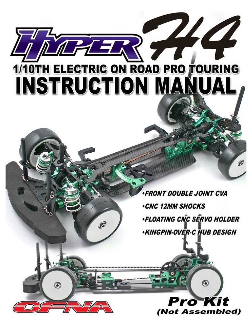
Ofna Racing Hyper H4 User manual

Ofna Racing

Ofna Racing Hyper H4 User manual

Ofna Racing ULTRA GT LX User manual

Ofna Racing

Ofna Racing ULTRA GT LX User manual

Ofna Racing DM-ONE-SPEC e User manual

Ofna Racing

Ofna Racing DM-ONE-SPEC e User manual

Ofna Racing X2 TRUGGY User manual

Ofna Racing

Ofna Racing X2 TRUGGY User manual

Ofna Racing nitro OB 4 User manual

Ofna Racing

Ofna Racing nitro OB 4 User manual

Ofna Racing Hyper H4 User manual

Ofna Racing

Ofna Racing Hyper H4 User manual

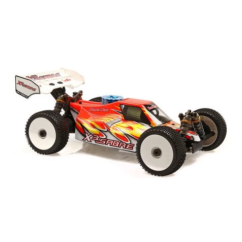
Ofna Racing X3 Sabre User manual

Ofna Racing

Ofna Racing X3 Sabre User manual

Ofna Racing DIRT OVAL User manual

Ofna Racing

Ofna Racing DIRT OVAL User manual

Ofna Racing Ultra LX Pro User manual

Ofna Racing

Ofna Racing Ultra LX Pro User manual

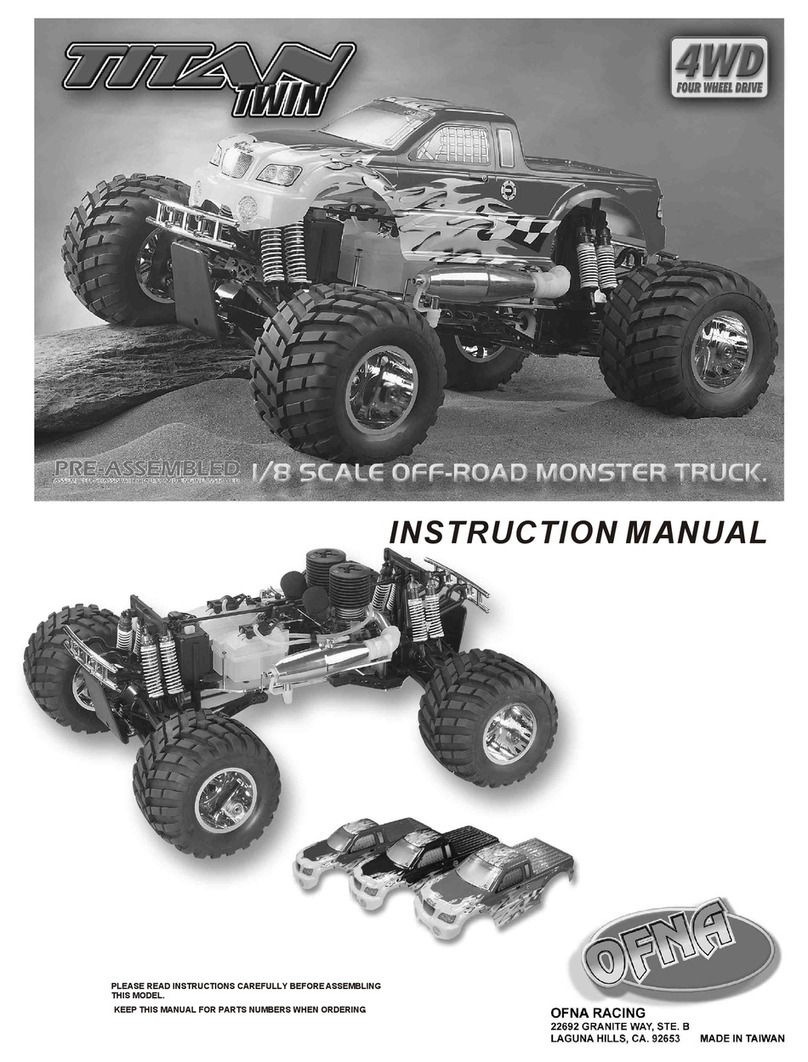
Ofna Racing titan twin User manual

Ofna Racing

Ofna Racing titan twin User manual

Ofna Racing hyper star electric User manual

Ofna Racing

Ofna Racing hyper star electric User manual

Ofna Racing ULTRA GTP II 34316 User manual

Ofna Racing

Ofna Racing ULTRA GTP II 34316 User manual

Ofna Racing PirateMT Sport User manual

Ofna Racing

Ofna Racing PirateMT Sport User manual

Ofna Racing Nitro Z10 User manual

Ofna Racing

Ofna Racing Nitro Z10 User manual

Ofna Racing Hyper7TQ Sport User manual

Ofna Racing

Ofna Racing Hyper7TQ Sport User manual

Ofna Racing DM-ONE PRO TOURING X-SIZE NITRO SEDAN User manual

Ofna Racing

Ofna Racing DM-ONE PRO TOURING X-SIZE NITRO SEDAN User manual

Ofna Racing DM-1 Spec User manual

Ofna Racing

Ofna Racing DM-1 Spec User manual

Ofna Racing Ultra LX Comp User manual

Ofna Racing

Ofna Racing Ultra LX Comp User manual

Ofna Racing DM-ONE-SPEC User manual

Ofna Racing

Ofna Racing DM-ONE-SPEC User manual

Ofna Racing Nexx 10SC User manual

Ofna Racing

Ofna Racing Nexx 10SC User manual

Ofna Racing PICCO OFF ROAD Assembly instructions

Ofna Racing

Ofna Racing PICCO OFF ROAD Assembly instructions

Popular Motorized Toy Car manuals by other brands

HOMCOM 370-173 Assembly instruction

HOMCOM

HOMCOM 370-173 Assembly instruction

Square PARSEC-C instruction manual

Square

Square PARSEC-C instruction manual

Vaterra TWIN HAMMERS VTR03085 owner's manual

Vaterra

Vaterra TWIN HAMMERS VTR03085 owner's manual

REVELL 85-1285 manual

REVELL

REVELL 85-1285 manual

KM K8 instruction manual

KM

KM K8 instruction manual

21st Century Toys RC09037 owner's manual

21st Century Toys

21st Century Toys RC09037 owner's manual

PIKO BR 218 instruction manual

PIKO

PIKO BR 218 instruction manual

DICKIE TOYS Rally Stryker operating instructions

DICKIE TOYS

DICKIE TOYS Rally Stryker operating instructions

Jamara Lamborghini Aventador LP700 2,4GHz instructions

Jamara

Jamara Lamborghini Aventador LP700 2,4GHz instructions

Little Tikes LTXtreme AIR CHARGERS 3-IN-1 STUNT LOOP TRACK... Assembly lnstructions

Little Tikes

Little Tikes LTXtreme AIR CHARGERS 3-IN-1 STUNT LOOP TRACK... Assembly lnstructions

Elekit JS-685E instruction manual

Elekit

Elekit JS-685E instruction manual

Kyosho MINI-Z Racer MR-015 RML Type instruction sheet

Kyosho

Kyosho MINI-Z Racer MR-015 RML Type instruction sheet

Actionbikes A30 owner's manual

Actionbikes

Actionbikes A30 owner's manual

Hong Nor Nexx 10SC instructions

Hong Nor

Hong Nor Nexx 10SC instructions

Horizon Educational H-racer 2.0 Assembly guide

Horizon Educational

Horizon Educational H-racer 2.0 Assembly guide

Radio Shack Avalanche 60-4330 owner's manual

Radio Shack

Radio Shack Avalanche 60-4330 owner's manual

Vintage Air 1981-87 CHEV PICK-UP manual

Vintage Air

Vintage Air 1981-87 CHEV PICK-UP manual

Gizmo Genesis instruction manual

Gizmo

Gizmo Genesis instruction manual

manuals.online logo
manuals.online logoBrands
  • About & Mission
  • Contact us
  • Privacy Policy
  • Terms and Conditions

Copyright 2025 Manuals.Online. All Rights Reserved.