16 - 56 Is170TC-0 Rev. 211004-0
Component description English
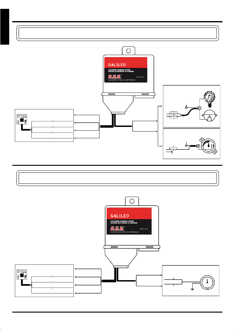
+12 VOLT
IGNITION
RED WIRE
It is important that the +12 V ignition is connected where the power is not timed, or is
disabled during start-ups. Verification procedure:
• connect a digital multimeter and select the voltage range 20 V;
• turn the ignition key on. The display on the multimeter must show 12 V;
• wait a few seconds:
- if the voltage goes to 0 V it is timed, try another power supply point;
- if the voltage remains steady at +12 V, continue testing this power supply point;
• start the engine while observing the multimeter. While the starter is cranking the engine,
make sure that the +12 V power supply is steady, and that it does not go to 0 V while
cranking and back to +12 V as soon as the engine is started:
- if the voltage goes to 0 V, try another power supply point;
- if the voltage remains steady at +12 V, this is the appropriate power supply to
which the RED wire of the “GALILEO” is to be connected.
We recommend using 7,5 A MAX. fuses.
The RED-BLACK wire is connected to battery positive through a protector fuse
(MAX. 7,5 A). It allows the “GALILEO” to maintain memory of all data pertinent to
carburetion (DEFAULT value). If the RED-BLACK wire is disconnected from battery, the
memorised data pertinent to carburetion are erased from memory.
All other parameters related to the “GALILEO” configuration are memorised in a special
memory and can be modified or erased only through laptop COMPUTER or the special
HAND-HELD TESTER.
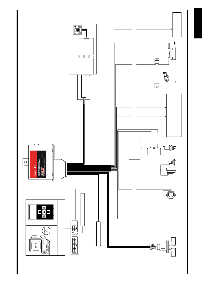
Inside the “GALILEO” there is a normally closed relay with its exits (30 e 87A) connected
to the YELLOW wires. These wires can be utilised to open the following circuits:
• INJECTORS: on those vehicles where the E.C.U. does not perform injector diagnostics,
thus it is not necessary to use any simulation.
• CHECK-ENGINE INDICATOR.
• MEMORY RESET: in a case when, during alternative fuel operation, the E.C.U. memorises
anomalous sensor read-out.
The GAS accessories output (BLUE wire from the “GALILEO” E.C.U.) supplies a +12 V
power output for the GAS electrovalves (pressure regulator and lock-off valves) and for all
devices (timing advance processors and emulators) that require voltage during GAS mode
to operate.
The GAS accessories output is controlled by a SAFETY-CAR safety device, which is integrated
in the “GALILEO” E.C.U.. The SAFETY-CAR function enables the GAS electrovalve only
when the engine is running.
In this way, if (for example) the engine stalls, the GAS supply is automatically turned off.
By using the diagnostic plug, it is possible to connect the “GALILEO” either to a PC through
serial interface on which a special programming software is installed, or to the hand-held
tester. In either case several menus are available. From these menus it is possible to
configure the “GALILEO” to the characteristics of different vehicle types, as well as to check
for correct operation of the chosen configurations.
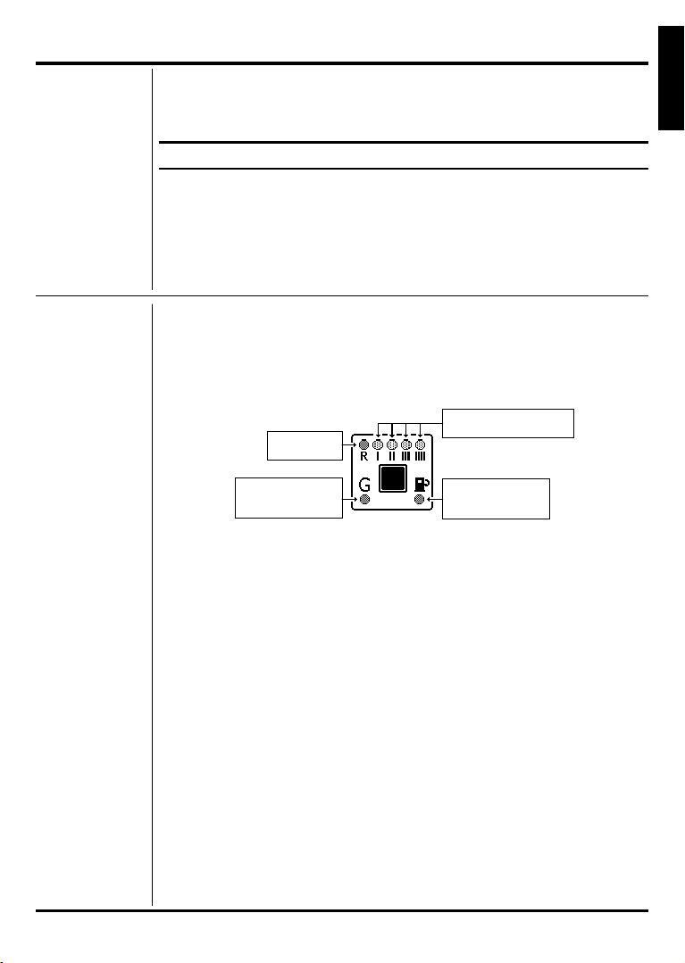
+12 VOLT
BATTERY
RED-BLACK
WIRE
YELLOW WIRES
UTILISATION:
INJECTORS
CHECK-ENGINE
INDICATOR OR
MEMORY RESET
DIAGNOSTIC
PLUG
GAS
ACCESSORIES
OUTPUT
BLUE WIRE