PDi BELLA-HD PD295-004 User manual
USER MANUAL
Document Number: PD196-426R1
mymedTV.com
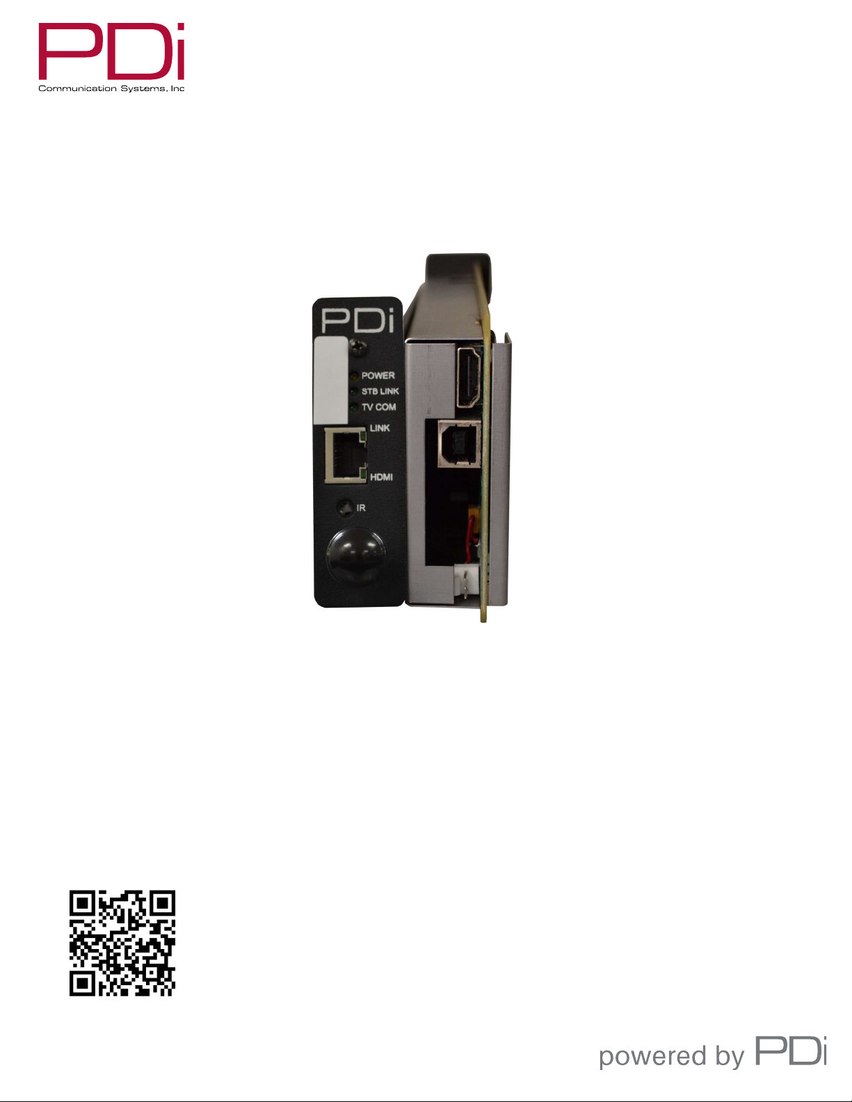
PD295-004
BELLA-HD™ Set Top Box
Interface Module
MODEL:
PDi BELLA-HD Interface
Document Number:
PD196-426R1
User Manual Page 2 of 27
PDi Communication Systems, Inc. ▪ 40 Greenwood Ln ▪ Springboro, Ohio 45066 USA ▪ www.PDiarm.com and www.mymedTV.com ▪ Phone 800.628.9870
Contents
CAUTIONS AND WARNINGS .........................................................................3
IMPORTANT SAFETY INSTRUCTIONS .....................................................4
Introduction ..........................................................................................................5
Compatibility ........................................................................................................5
Mounting and Powering the Interface Module ....................................5
Connections ..........................................................................................................6
Wall Mounted Televisions .......................................................................6
Wall Mounted TV – Data, Power, and IR Emitter Cable
Installation ...............................................................................................6
Wall Mounted TV - RF Cable Installation ..................................8
Arm Mounted Televisions ..............................................................................8
Arm Mounted TV – Data, Power, and IR Emitter Cable
Installation ...............................................................................................8
Arm Mounted TV - RF Cable Installation ...................................9
TV Setup – Most PDi TVs ............................................................................. 12
TV Setup – A-Series ........................................................................................ 13
TV Setup – medTAB ....................................................................................... 13
Verifying and Troubleshooting Connections ..................................... 13
Power .............................................................................................................. 14
STB Link ......................................................................................................... 14
TV COM .......................................................................................................... 14
LINK ................................................................................................................. 14
HDMI ............................................................................................................... 14
Interface Module Setup Menus................................................................. 15
Accessing Interface Module Setup Menus on most PDi TVs 15
Accessing Interface Module Setup Menus on medTAB-C ...... 15
Menus 1 ~ 5 ................................................................................................. 16
Menu 6 ........................................................................................................... 17
Programming the Interface Module ...................................................... 17
Programming the IR Code Set............................................................. 17
Keypad Programming (Mapping) Instructions .......................... 18
Programming for Off-Air Non-Satellite Channels Using Off-
Air RF Pass-Thru ....................................................................................... 19
An Example for Off-Air RF Pass-Thru ...................................... 19
Programming the STB Signal Input Type ...................................... 20
Restoring Factory Default Settings......................................................... 20
Operation ............................................................................................................ 20
Cable/Satellite TV Operation .............................................................. 20
Off-Air TV Operation (Optional) ........................................................ 21
Troubleshooting .............................................................................................. 21
Appendix A - Control Device (TV) Key Reference ........................... 23
Appendix B - STB Command Reference ............................................... 24
Appendix C - Factory Defaults .................................................................. 25
Limited Warranty ........................................................................................... 27

MODEL:
PDi BELLA-HD Interface
Document Number:
PD196-426R1
User Manual Page 3 of 27
PDi Communication Systems, Inc. ▪ 40 Greenwood Ln ▪ Springboro, Ohio 45066 USA ▪ www.PDiarm.com and www.mymedTV.com ▪ Phone 800.628.9870
CAUTIONS AND WARNINGS
WARNING: To reduce the risk of fire or electric shock, do not expose
this apparatus to rain or moisture.
WARNING: To prevent injury, this apparatus must be
securely attached to the equipment rack in accordance
with the installation instructions.
WARNING: Do not install this equipment in a confined
space such as a bookcase or similar unit.
Modifications
Any changes or modifications made to this device that
are not expressly approved by PDi may void the user’s
authority to operate the equipment.
Cables
Connections to this device must be made with shielded cables with
metallic RFI/EMI connector hoods to maintain compliance with FCC
Rules and Regulations.
Safety Instructions
To avoid any malfunctions of the unit and associated components
and unwanted electric shock or fire accidents, please observe the
following:
• Review the manual for your STB unit for safety instructions
• Review the manual for your PDI TV for safety instructions
• Review the manual for the rack unit.
Placement
Avoid placing the unit in surroundings with:
• High temperature (over 40 C) or high humidity (over 90%).
• Direct sunlight or heat sources, like radiators or ovens.
• Excessive dust.
• Electrostatic effect.
• Vibration, impact, or tilted surface.
Wet Areas
• Avoid rain and moisture.
• DO NOT set containers with liquid, such as vases, on top of the
unit.
• Avoid placing the unit in areas where there is dripping and/or
splashing.
• Avoid placing unit near standing water.
Oxygen Environment
• DO NOT use in an oxygen tent or an oxygen chamber. Such
use may cause a fire hazard.
SERVICING
User Servicing
If your product is not operating correctly or exhibits a marked
change in performance and you are unable to restore normal
operation by following the detailed procedure in its operating
instructions, do not attempt to service it yourself as opening or
removing covers may expose you to dangerous voltage or other
hazards. Refer all servicing to qualified service personnel.
Damage Requiring Service
Unplug this product and refer servicing to qualified service personnel
under the following conditions:
• If liquid has been spilled, or objects have fallen into the
product.
• If the product has been exposed to rain or water.
• If the product does not operate normally by following the
operating instructions. Adjust only those controls that are
covered by the operating instructions as an improper
adjustment of other controls may result in damage and will
often require extensive work by a qualified technician to
restore the product to its normal operation.
• If the product has been dropped or damaged in any way.
• When the product exhibits a distinct change in
performance which indicates a need for service.
Replacement Parts
When replacement parts are required, be sure the service technician
has used replacement parts specified by the manufacturer or have
the same characteristics as the original part. Unauthorized
substitutions may result in fire, electric shock, or other hazards.
Safety Check
Upon completion of any service or repairs to this product, ask the
service technician to perform safety checks to determine that the
product is in safe operating conditions.
Cleaning & Disinfecting
• Unplug before cleaning.
• Use a soft cloth to clean.
• Do not use harsh chemicals such as solvents.
COPYRIGHT, DISCLAIMER, TRADEMARKS
Copyright
PDi Communication Systems, Inc. claims proprietary right to the
material disclosed in this manual. This manual is issued in confidence
for installation and operational information only and may not be
used to manufacture anything shown herein. Copyright by PDi
Communication System, Inc. All rights reserved.
Disclaimer
The author and publisher have used their best efforts in preparing
this manual. PDi Communication Systems, Inc. makes no
representation or warranties with respect to the accuracy or
completeness of the contents of this manual and specifically disclaim
any implied warranties of merchantability or fitness for any
MODEL:
PDi BELLA-HD Interface
Document Number:
PD196-426R1
User Manual Page 4 of 27
PDi Communication Systems, Inc. ▪ 40 Greenwood Ln ▪ Springboro, Ohio 45066 USA ▪ www.PDiarm.com and www.mymedTV.com ▪ Phone 800.628.9870
particular purpose and shall in no event be liable for any loss of profit
or any other damages, including but not limited to special, incidental,
consequential or other damages for the use of this manual. The
information contained herein is believed accurate, but is not
warranted, and is subject to change without notice or obligation.
Trademarks
All brand names and product names used in this manual are
trademarks, registered trademarks, or trade names of their
respective holders. PDi and Better Solutions Are Within Reach are
registered trademarks of PDi Communication Systems, Inc
IMPORTANT SAFETY INSTRUCTIONS
1. Read these instructions.
2. Keep these instructions.
3. Heed all warnings.
4. Follow all instructions.
5. Do not use this apparatus near water.
6. Clean only with dry cloth.
7. Do not block any ventilation openings. Install in accordance with
the manufacturer’s instructions.
8. Do not install near any heat sources such as radiators, heat
registers, stoves, or other apparatus (including amplifiers) that
produce heat.
9. Do not defeat the safety purpose of the polarized or grounding-
type plug. A polarized plug has two blades with one wider than the
other. A grounding type plug has two blades and a third grounding
prong. The wide blade or the third prong is provided for your safety.
If the provided plug does not fit into your outlet, consult an
electrician for replacement of the obsolete outlet.
10. Protect the power cord from being walked on or pinched
particularly at plugs, convenience receptacles, and the point where
they exit from the apparatus.
11. Only use attachments/accessories specified by the manufacturer.
12. Use only with the cart, stand, tripod, bracket, or table specified by
the manufacturer, or sold with the apparatus. When a cart is used,
use caution when moving the cart/apparatus combination to avoid
injury from tip-over.
13. Unplug this apparatus during lightning storms or when unused
for long periods of time.
14. Refer all servicing to qualified service personnel.
Servicing is required when the apparatus has been damaged in any
way, such as power-supply cord or plug is damaged, liquid has been
spilled or objects have fallen into the apparatus, the apparatus has
been exposed to rain or moisture, does not operate normally, or has
been dropped.
15. This appliance should be mounted in an equipment rack as
recommended by the manufacturer.
16. Care should be taken so that objects do not fall and liquids are
not spilled into the enclosure through openings.
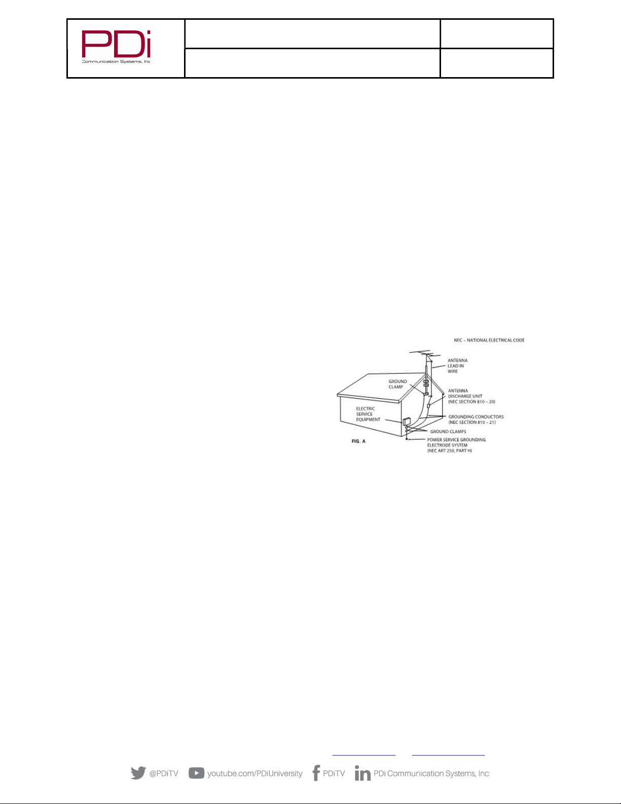
17. If an outside antenna or cable system is connected to the
video product, be sure the antenna or cable system is grounding
so as to provide some protection against voltage surges and built-
up static charges. Section 810 of the National Electrical Code,
ANSI/NFPA 70, provides information with respect to proper
grounding of the mast and supporting structure, grounding of the
lead-in wire to an antenna discharge unit, size of grounding
conductors, location of antenna-discharge unit, connection to
grounding electrodes, and requirements for the grounding
electrode. See Figure A.
NOTE: This reminder is provided to call the CATV system
installer’s attention to article 820-40 of the NEC that provides
guidelines for proper grounding and, in particular, specifies that
the cable ground shall be connected to the grounding system of
the building, as close to the point of cable entry as practical.

MODEL:
PDi BELLA-HD Interface
Document Number:
PD196-426R1
User Manual Page 5 of 27
PDi Communication Systems, Inc. ▪ 40 Greenwood Ln ▪ Springboro, Ohio 45066 USA ▪ www.PDiarm.com and www.mymedTV.com ▪ Phone 800.628.9870
Introduction
Traditionally a facility pays for dozens or hundreds of cable/satellite channels but only has a small number of set-top-boxes, each
locked on a single channel, and combined onto the cable plant. When a patient wants to view a channel that isn’t on the cable plant,
the nurse must go to the head end and change one of the receivers or tell the patient the channel is not available. To provide the full
channel package to each patient, the set-top-box may be placed next to each TV in the patient area. Unfortunately, when the IR remote
is used by one patient to change channels, any TV nearby will also change.
The PDi Interface Module is designed to improve the patient experience interacting with a TV at a facility in which the channels come
from a cable/satellite set-top-box. It allows direct access to all set-top-box functions via PDi TV keypad, IR remote, and pillow speaker.
It gives patients access to every channel the facility is paying for and allows patients to easily switch between cable/satellite, in-house
DVD, and rooftop antenna channels. The interface module can pay for itself by eliminating modulators, splitters, and combiners in
most environments. It removes the need to modulate signals for distribution by sending HDMI from each set-top-box directly to an
associated TV. It offers customizable key mapping and works in many retrofit installations. Best of all it’s made in America!
Compatibility
The PDi interface module uses HDBase-T technology to bring uncompressed HDMI signals from the set top box at the head-end to the
TV. It also forms a communication bridge between the PDi TV and set top box.
As of this print, the following set-top-boxes have been tested to work with the PDi interface module. Contact PDi for compatibility
with other models.
Provider Set Top Box Model PDi Interface Module
Min Firmware Version
Cablevision Scientific Atlanta Explorer 4250HD V5.00
Charter/Spectrum Motorola DCH6200 V5.00
Charter/Spectrum Motorola DCT2224 V5.00
Comcast/Xfiniti Pace DC50X V5.00
Comcast/Xfiniti Pace PXD01ANI V5.00
Comcast/Xfiniti Comcast PR150B V5.00
Comcast/Xfiniti Comcast RNG110 V5.00
COX COX 3250HD
(Scientific Atlanta Explorer 3250HD)
V5.00
COX COX DTA250HD V5.00
DirecTV DirecTV H25 V5.00
Dish Dish ViP211k V5.00
Dish Dish ViP222k V5.00
Haivision Haivision Stingray V5.00
Haivision Haivision Mantaray V5.00
Time Warner Cable/Spectrum Cisco DTA 271HD V5.00
Time Warner Cable/Spectrum Cisco 8742 HDC V5.00
Time Warner Cable/Spectrum Spectrum101-T V5.00
Verizon V5.00
Mounting and Powering the Interface Module
The PDi interface module is designed to slide into an industry standard mini-mod chassis and is powered by the chassis’ power
supply. Standard mini-mod rack mount chassis with power supply are suitable for the interface module. These include, but are not
limited to:
MODEL:
PDi BELLA-HD Interface
Document Number:
PD196-426R1
User Manual Page 6 of 27
PDi Communication Systems, Inc. ▪ 40 Greenwood Ln ▪ Springboro, Ohio 45066 USA ▪ www.PDiarm.com and www.mymedTV.com ▪ Phone 800.628.9870
ATX / Pico Digital MPC-12
Blonder Tongue MIRC-12V with MIPS-12C
Drake® RMM-12 with PSM121
Holland HMR with HMPS
When it is more desirable to have the set-top-box and interface module located near the TV, the module may be used in a stand-alone
configuration without the need for a mini-mod chassis. In this case the PDi PD106-747 power adapter (not included) should be used
to power the interface module. Since the interface module uses very little energy, it has no special ventilation requirements. A
DirectTV set-top-box can power the mini-mod in place of the rack mount chassis power supply.
Connections
The PD295-004 BELLA interface module connects to the TV via standard CAT6a cable. CAT6a provides a higher bandwidth needed for
the HDMI video signal and the length should not exceed 250 feet. BELLA must be powered via the rack mounted chassis, a standalone
power adapter, or via a USB power connection. The IR Emitter cable must also be connected to the module and adhered to the IR
window of the corresponding set-top-box. CAT6a, HDMI and power cables are not provided with the Bella.
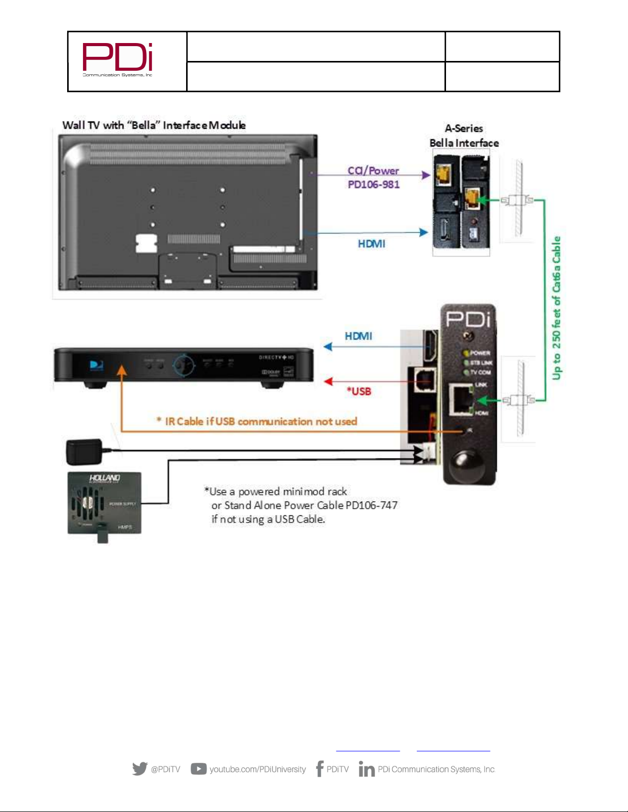
Wall Mounted Televisions
Wall Mounted TV – Data, Power, and IR Emitter Cable Installation
1. Connect 26 pin connector of cable PD106-981 to the TV’s 26 pin connector and the other end to the CCI connector on the BELLA
CCI port as shown below.
2. Connect an HMDI cable between the BELLA interface box and the TV.
3. Connect the CAT6a cable to the RJ45 port on the PD295-004 interface module.
4. Remove adhesive backer from the module and secure it to the rear of the TV.
5. For rack mounted interface module, connect rack minimod power cable to PD295-004. For stand-alone mounting, connect power
cord PD106-747 to PD295-004.
MODEL:
PDi BELLA-HD Interface
Document Number:
PD196-426R1
User Manual Page 7 of 27
PDi Communication Systems, Inc. ▪ 40 Greenwood Ln ▪ Springboro, Ohio 45066 USA ▪ www.PDiarm.com and www.mymedTV.com ▪ Phone 800.628.9870

MODEL:
PDi BELLA-HD Interface
Document Number:
PD196-426R1
User Manual Page 8 of 27
PDi Communication Systems, Inc. ▪ 40 Greenwood Ln ▪ Springboro, Ohio 45066 USA ▪ www.PDiarm.com and www.mymedTV.com ▪ Phone 800.628.9870
Wall Mounted TV - RF Cable Installation
The RF Output Signal cable from each set-top-box (STB) must also be routed to each remotely located television. Please refer to the
STB installation instructions for details.
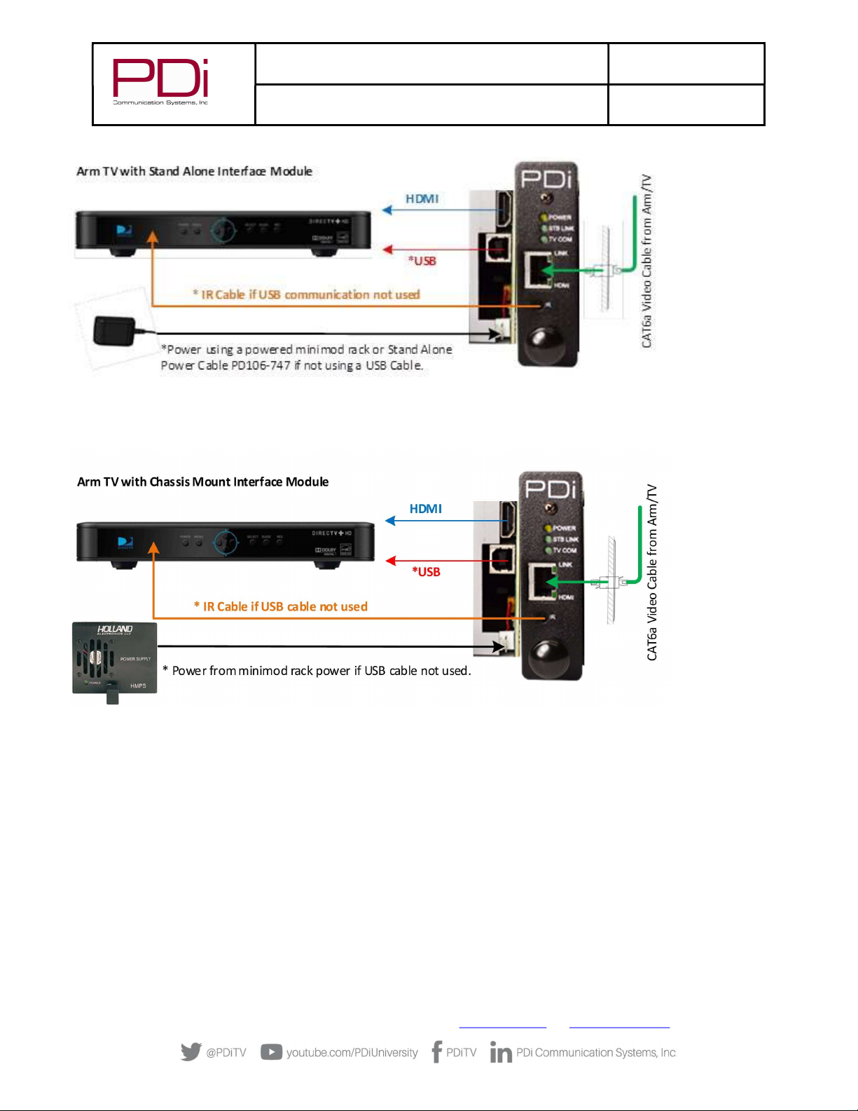
Arm Mounted Televisions
The PD295-004 interface module is also compatible with several of the PDi Arm Mounted televisions that incorporate a BELLA
interface. Models such as the medTV and medTAB can be used successfully with the interface module when ordered with the BELLA
option.
NOTE: Each TV and its Support Arm must be pre-wired with a CAT6a data cable. Please contact PDi Communication
Systems or your PDi distributor for assistance should your TV and/or Arm lack this cable.
Arm Mounted TV – Data, Power, and IR Emitter Cable Installation
The CAT6a cable used to connect the remotely located TV to the interface module should not exceed 250 feet in length. CAT6a, HDMI
and power cables are not provided with the interface module.
1. Connect one end of the CAT6a cable to the Data Cable from the Arm/TV. The in-room Data Connection is typically wall mounted as
illustrated below.
2. Connect the other end of the CAT6a cable to the RJ45 port on the front of the PD295-004 interface module.
3. If using a DirecTV set top box, connect the USB cable to the PD295-004. No other power supply is needed.
4. Connect the IR Emitter cable to the interface module if used (see note below).
5. Remove adhesive backer from IR Emitter and secure it to the IR receiver window of the STB.
6. For a chassis mounted interface module, connect chassis power cable to PD295-004. For stand-alone mounting, connect power
cord PD106-747 to PD295-004.
MODEL:
PDi BELLA-HD Interface
Document Number:
PD196-426R1
User Manual Page 9 of 27
PDi Communication Systems, Inc. ▪ 40 Greenwood Ln ▪ Springboro, Ohio 45066 USA ▪ www.PDiarm.com and www.mymedTV.com ▪ Phone 800.628.9870
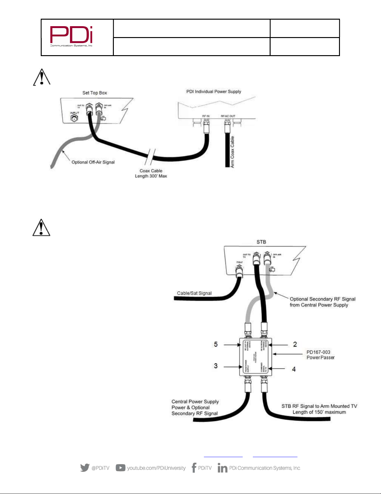
Arm Mounted TV - RF Cable Installation
Unlike AC powered wall mounted TV’s, PDi arm mounted television models receive their RF signal and TV power combined along a
connecting coax cable from an external power source. Special consideration must be used in handling the low voltage AC power found
on the RF signal coax cable.
Two types of external power supplies are used with arm mounted televisions: individual or central style. The individual power supply
mounts near the TV injecting power from a nearby AC outlet onto the incoming coaxial cable. The central supply injects power onto 10
separate coax cables simultaneously and mounts in a wiring closet as far as 150 feet away from the TV’s. Connection of the RF signal
coax cable for each style of power supply is detailed below.
Individual Style Power Supply - RF Cable Installation
Signal connections for an arm mounted TV powered from an individual power supply requires a single coax cable no longer than 300
feet, connected at the set-top-box’s “Output to TV” connection.
Some set-top-boxes also allow for the connection of an external Antenna or other signal source via an “OFF-AIR IN” connection. Please
consult your set-top-box installation instructions for details.
MODEL:
PDi BELLA-HD Interface
Document Number:
PD196-426R1
User Manual Page 10 of 27
PDi Communication Systems, Inc. ▪ 40 Greenwood Ln ▪ Springboro, Ohio 45066 USA ▪ www.PDiarm.com and www.mymedTV.com ▪ Phone 800.628.9870
NOTE: The drawing below is representative of the typical set-top-box. Your box may vary in appearance.
Central Style PDI -772HE Power Supply - RF Cable Installation
Low voltage AC TV power is present on each central power supply TV coax cable. A PDi Power Passer (part number PD167-003) is
required to route the AC power on the coax cable around any externally connected device such as the Satellite Box. A Power Passer is
required for each TV/STB connection. For new installations, the use of a PDI-772HE-IND instead of PDI-772-HE will eliminate the
need for the power passers.
NOTE: The PD167-003 Power Passer is an optional device NOT supplied with the interface module and is only required
for centrally powered arm mounted televisions. Please contact PDi or your PDi distributor to order this device.
1. Remove power from the TV at the central power
supply.
2. Connect a coaxial cable from the STB “OUT TO
TV” to the Power Passer’s “RF IN FROM
EXTERNAL DEVICE”.
3. Locate the coaxial cable from the central power
supply. Connect this cable to “FROM POWER
SUPPLY”.
4. Connect the coaxial cable from the TV to
“COMBINED SIGNAL TO TV.” The TV coax should
be limited to 150’ to accommodate the central
power supply coax length limitations.
5. Connect an Optional Secondary RF signal coaxial
cable from the Power Passer’s “RF OUT TO
EXTERNAL DEVICE” to the set-top-box “OFF-AIR
IN”. This connection is only necessary if you
wish to view TV signals that are already present
on your system in addition to set-top-box
signals.

MODEL:
PDi BELLA-HD Interface
Document Number:
PD196-426R1
User Manual Page 11 of 27
PDi Communication Systems, Inc. ▪ 40 Greenwood Ln ▪ Springboro, Ohio 45066 USA ▪ www.PDiarm.com and www.mymedTV.com ▪ Phone 800.628.9870
Central Style PDI-772HE-IND Power Supply - RF Cable Installation
Low voltage AC TV power is present on each central power supply TV RF out port. Each RF In port is designed to be connected to a
separate RF source with minimal loss and high isolation.
1. Remove power from the TV at the central power supply.
2. Connect a coaxial cable from the set-top-box “OUT TO TV” to one of the 10 “RF IN” ports on the PDI-772HE-IND.
3. Connect the coaxial cable from the TV to “RF OUT”. The TV coax should be limited to 150’ to accommodate the central power
supply coax length limitations.
4. Connect an Optional Secondary RF signal coaxial cable to the set-top-box “OFF-AIR IN”. This connection is only necessary if you
wish to view TV signals that are already present on your system in addition to set-top-box signals. Signal strength entering the
set-top-box should be +3dBmV to +10dBmV.
MODEL:
PDi BELLA-HD Interface
Document Number:
PD196-426R1
User Manual Page 12 of 27
PDi Communication Systems, Inc. ▪ 40 Greenwood Ln ▪ Springboro, Ohio 45066 USA ▪ www.PDiarm.com and www.mymedTV.com ▪ Phone 800.628.9870
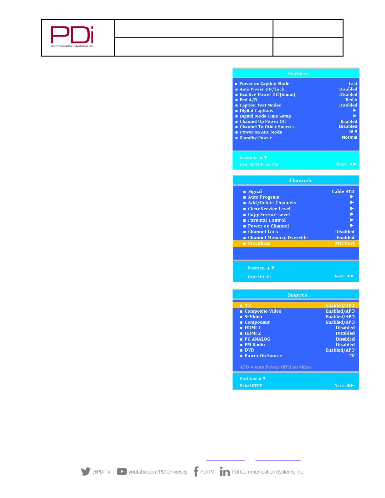
TV Setup – Most PDi TVs
To establish communications to the interface module, the CCI port on the TV
must be active and you must have a PDi programming remote PD108-420 (not
included). Follow the steps below:
1. Press SETUP to enter the TV’s setup menu.
2. From the setup menu select “Features”.
3. If the “Standby Power” setting shows in this menu, change it to
“Normal”. Some TV’s do not have this setting so this step can be
ignored. Other TV’s may operate the interface module on any “Standby
Power” setting. This can be determined by trying it or contacting PDi.
4. From the initial setup menu, select “Channels”.
5. Change the “Pro:idiom” option to “MTI Port” or “Data Port”. Some TV’s
do not have this setting. In that case, this step can be ignored.
6. From the initial setup menu, select “Sources”. Set each item as detailed
below.
The TV Source Setup must properly reflect the actual connections to
the TV. Incorrect settings will result in loss of programming or the
addition of blank signal sources. In most installations, both
cable/satellite and off-air programming is delivered over RF so the “TV
Tuner” must be enabled. If the cable/satellite channels are delivered
over an alternate method such as HDMI, then that source must be
enabled. All unused sources should be disabled.

MODEL:
PDi BELLA-HD Interface
Document Number:
PD196-426R1
User Manual Page 13 of 27
PDi Communication Systems, Inc. ▪ 40 Greenwood Ln ▪ Springboro, Ohio 45066 USA ▪ www.PDiarm.com and www.mymedTV.com ▪ Phone 800.628.9870
TV Setup – A-Series
To establish communication to interface module the CCI port on the TV must be active and you must have a PDi programming remote
PD108-420 (not included).
1. From the TV, open the TV Setup Menu by pressing SETUP on the programming remote.
2. Select “Sources” and then select “Source Enable”. Set each item as detailed below.
The TV Source Setup must properly reflect the actual connections
to the TV. Incorrect settings will result in loss of programming or
the addition of blank signal sources. In most installations, both
cable/satellite and off-air programming is delivered over RF so
the “TV” must be enabled. If the cable/satellite channels are
delivered over an alternate method such as HDMI, then that
source must be enabled. All unused sources should be disabled.
TV Setup – medTAB
medTAB14C, medTAB19C, and medTAB16C are compatible with PDi interface modules. To establish communication to interface
module the CCI port on the TV must be active. Setup on the medTAB14C and medTAB16C can be completed with a PDi programming
remote PD108-420 (not included). medTAB19C setup is completed through onscreen touchscreen controls.
1. From the TV app, open the TV Settings Menu, by pressing SETUP on the programming remote or by pressing Settings on the
touchscreen TV controls. Enter password (“45066” is factory default).
2. Select “Advanced Option”.
3. Select “Features” then select “Input Sources”. Set each item as detailed below.
The TV Source Setup must properly reflect the actual connections to the TV. Incorrect settings will result in loss of
programming or the addition of blank signal sources. In most installations, both cable/satellite and off-air programming is
delivered over RF so the “TV” must be enabled. If the cable/satellite channels are delivered over an alternate method such as
HDMI, then that source must be enabled. All unused sources should be disabled.
Verifying and Troubleshooting Connections
The following steps verify the data connections between the STB and TV. These instructions assume you have
followed the previous connection and TV setup sections of this manual.
1. Power the TV.
2. Power the set-top-box.
3. Power the interface module. Note-If using a DirectTV box, power is through the USB cable.
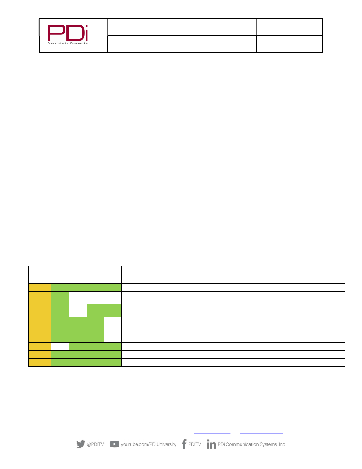
4. Examine the front mounted status lights on the PD295-004 interface module. It contains a POWER, STB (set-
top-box), TV COM, LINK, and HDMI status lights.
a. Each light will turn green (yellow for power) when properly connected.
b. A dark (Off) status light indicates a problem.
c. A blinking STB LINK LED indicates data transfer. HDMI blinking means HDMI video content is not
copy protected.
d. All 5 lights lit indicate all connections are working properly and HDMI is being sent to the TV.
Please review the “Troubleshooting” section for additional help.
NOTE: While the LINK light indicates a working connection to the TV, it does not confirm the audio/video (RF or
HDMI) from the STB is connected to the correct TV.
MODEL:
PDi BELLA-HD Interface
Document Number:
PD196-426R1
User Manual Page 14 of 27
PDi Communication Systems, Inc. ▪ 40 Greenwood Ln ▪ Springboro, Ohio 45066 USA ▪ www.PDiarm.com and www.mymedTV.com ▪ Phone 800.628.9870
Power
On – Yellow Solid – Indicates that the minimod processor has power and is running properly.
Off – No power supplied to the minimod, either through the USB or power connector.
STB Link
Note: If a DirecTV box is not used or is used but not connected with the USB cable, this LED will not be active. The minimod box can be
powered with a separate wall wart and the IR output used to control the set-top-box.
On – Green – Indicates communication between the minimod and the DirecTV set-top-box. It may take up to 2 minutes after power is
cycled before the light will turn on.
Off – No set-top-box communication. Check USB cable connection. Cycle power to set-top-box.
TV COM
On – Green – Indicates communication to the remote TV. This may blink occasionally indicating TV communication.
Off – No TV communication. If this light is off and the TV LINK light is on solid, there is a CCI cable connection problem inside the TV.
LINK
On – Green – Solid – Indicates an active connection to the remote TV. This indicator is different in functionality than the TV COMM led.
This indicates the CAT6 cable connection is good between the minimod and the TV, but not necessarily communication to the TV
board. See the TV COMM description above.
Off – No CAT6 connection to the TV. If this light is off and the POWER light is on solid, there is a CAT6 cable connection problem
between the minimod and the TV.
HDMI
On – Green – Blinking – Indicates an active HDMI video stream connection to the TV. This indicator is different in functionality than
the TV COMM led. This indicates the CAT6 cable connection is good between the minimod and the TV, but not necessarily
communication to the TV board. See the TV COMM description above.
Off – If this light is off and the TV LINK light is on, check the HDMI input connection. If both TV LINK and TV HDMI lights are off, there
is no CAT6 connection to the TV. If this light is off and the POWER light is on solid, there is a CAT6 cable connection problem between
the minimod and the TV. The HDMI input can be working and this light be off it the HDMI signal is not being received by the TV.
POWER STB
LINK
TV
COM
LINK HDMI SUGGESTIONS
OFF
OFF
OFF
OFF
OFF
1. Verify interface module is powered (USB or Power adapter)
ON
ON
ON
ON
ON
1. All connections are proper – HDMI may be solid green or blinking.
ON
ON
OFF
OFF
OFF
1. No CAT6a connection to TV
2. No power on TV.
ON
ON
OFF
ON
ON
1. CCI connection issue inside TV
2.
ON ON ON ON OFF
1. No HDMI input from set-top-box.
2. No HDMI connection inside of TV.
3.
4.
ON
OFF
ON
ON
ON
1. Press RESET button on set-top-box. Wait 2 minutes for STB to reboot.
ON
ON

MODEL:
PDi BELLA-HD Interface
Document Number:
PD196-426R1
User Manual Page 15 of 27
PDi Communication Systems, Inc. ▪ 40 Greenwood Ln ▪ Springboro, Ohio 45066 USA ▪ www.PDiarm.com and www.mymedTV.com ▪ Phone 800.628.9870
Interface Module Setup Menus
The interface module is configurable from Setup menus accessed by the TV programming remote or onscreen touchscreen controls.
The following instructions assume you have connected the TV, interface module, STB, and the various components according to the
previous instructions contained in this manual.
Accessing Interface Module Setup Menus on most PDi TVs
1. Make certain the STB and interface module are powered. See the instructions that came with the STB for more details.
NOTE: Some set-top-boxes (STBs) require several minutes following application of initial power to effectively respond
to commands. Please allow enough time for the STB to properly initialize.
2. Stand in front of the TV and press the SETUP button on the PD108-420 programming remote
3. When the TV Setup menu appears on the TV’s screen, press SETUP a second time to display the interface module setup menu.
4. Press the “CH▲” or “CH▼” on the remote to highlight the desired option. To advance to the next page, press “CH▼” when the
bottom item on the list is highlighted.
5. Press “VOL►” or “VOL◄” on the remote to cycle through a menu item’s setting options.
6. When finished, press SETUP to exit the “interface module setup” menu and save changes.
Accessing Interface Module Setup Menus on medTAB-C
1. Make certain the STB and interface module are powered. See the instructions that came with the STB for more details.
NOTE: Some set-top-boxes (STBs) require several minutes following application of initial power to effectively respond
to commands. Please allow enough time for the STB to properly initialize.
2. From the TV app, open the TV Settings Menu, by pressing SETUP on the programming remote or by pressing Settings on the
touchscreen TV controls. Enter password (“45066” is the factory default).
3. Select Advanced Option then press SETUP on the programming remote OR tap anywhere on the screen to open the STB interface
module setup menu.
4. Press the “CH▲” or “CH▼” on the programming remote OR use the touchscreen navigation arrows ▲ ▼ to highlight the desired
option. To advance to the next page, press “CH▼” or ▼ when the bottom item on the list is highlighted.
5. Press “VOL►” or “VOL◄” on the programming remote OR use the touchscreen navigation arrows ► ◄to cycle through a menu
item’s setting options.
6. When finished, press SETUP on the programming remote OR press Settings on the touchscreen controls to exit the “interface
module setup” menu and save changes. NOTE: FAILURE TO EXIT the interface module setup menu by following this step 6
could result in patient access to interface module setup menus.

MODEL:
PDi BELLA-HD Interface
Document Number:
PD196-426R1
User Manual Page 16 of 27
PDi Communication Systems, Inc. ▪ 40 Greenwood Ln ▪ Springboro, Ohio 45066 USA ▪ www.PDiarm.com and www.mymedTV.com ▪ Phone 800.628.9870
Menus 1 ~ 5
Menus 1, 2, 3, 4 and 5 provide the mapping content of a control device’s keypad buttons. The factory default settings are shown in the
menus pictured here in this manual. A complete listing of STB functions is provided in appendix A.
The left menu column “- TV KEY -” contains a listing of common control buttons found on pillow speakers, remotes, and television
keypads.
The right menu column “- STB COMMAND-” contains default settings that work well with most STB’s. Adjustment can only be made to
items in the right column.
NOTE: A STB menu item that is blank does not provide any STB control functionality and will
operate the standard TV function.
INTERFACE MODULE SETUP
-TV KEY- -STB COMMAND -
0 Digit 0
1 Digit 1
2 Digit 2
3 Digit 3
4 Digit 4
5 Digit 5
6 Digit 6
7 Digit 7
8 Digit 8
9 Digit 9
Dash (-) Info
Return: SETUP/OK/LAST
INTERFACE MODULE SETUP
-TV KEY- -STB COMMAND -
Up Arrow Up Arrow
Dn Arrow Down Arrow
Lt Arrow Left Arrow
Rt Arrow Right Arrow
Menu Guide
Home
Guide Guide
Info Info
Recall/Star ( * ) Prev Channel
Exit: Exit
Back (Nav) Back
Return: SETUP/OK/LAST
INTERFACE MODULE SETUP
-TV KEY- -STB COMMAND -
Play Play
Pause Pause
Stop Stop
Eject Record
Rewind Rewind
Fast Forward FFWD
Last Track Replay
Next Track Advance
Return: SETUP/OK/LAST
INTERFACE MODULE SETUP
-TV KEY- -STB COMMAND -
TV/FM Exit
TV/AV/Input
Ch List Guide
DVD Menu Guide
RED
GREEN
YELLOW
BLUE
Return: SETUP/OK/LAST
INTERFACE MODULE SETUP
-TV KEY- -STB COMMAND-
CH Up CH+
CH Dn CH-
Vol Up
Vol Dn
Last/Prev Ch Prev Channel
OK / Sel / Enter Select
CC
ARC/Ratio Down Arrow
Mute
Sleep Up Arrow
SAP/MTS
Return: SETUP/OK/LAST
INTERFACE MODULE SETUP
STB Model DirecTV
Settings >
TV Keys >
Numeric Keys >
Navigation Keys >
Media Play Keys >
Misc Keys >
Save: SETUP/OK Cancel: POWER

MODEL:
PDi BELLA-HD Interface
Document Number:
PD196-426R1
User Manual Page 17 of 27
PDi Communication Systems, Inc. ▪ 40 Greenwood Ln ▪ Springboro, Ohio 45066 USA ▪ www.PDiarm.com and www.mymedTV.com ▪ Phone 800.628.9870
Menu 6
Menu 6 provides STB configuration settings and firmware information.
MENU ITEM EXPLANATION
TV Input for STB Sets the TV’s signal type input to correspond to the STB’s signal output. The majority of STB’s utilize
modulated RF as the signal type and is the type shown in this instruction manual. TUNER is the default
setting. Additional settings are available for STB’s with different output signal types.
TV Chan for STB When the STB Signal Input is set to “Tuner”, this sets the channel the TV tunes to view the STB’s signal.
This setting should match the STB’s “CH” switch setting (which is usually 3 or 4) or the modulator
channel number.
STB Model Model number of set-top-box. Must match actual unit for proper operation.
NOTE: Changing the STB Model does not change the previous STB Key selections. If the STB Model is
changed, the STB Key selections should be reviewed to determine if they are the desired mappings for
the installation.
Restore Defaults for
STB
Press vol► to restore all interface settings, for the selected STB model, to factory defaults.
NOTE: Each STB model has a unique set of Factory Defaults. Selecting “Restore Factory Defaults”
changes the parameters to the Factory Defaults for the selected STB model and does not change the
“STB Model” selection.
The default settings for each supported STB are detailed below in “Appendix B – STB Functions and
Default Mapping Reference”
Flash Intface Pwr LED This provides a diagnostic tool to help determine if the TV is connected to the expected Satellite
Interface and STB. If “Flash Intface Pwr LED” is turned on, the “POWER” LED on the Satellite Interface
module controlled by this TV will flash rapidly. The STB controlled by this interface will also turn on
and off continuously.
NOTE: This is not a stored parameter. It is automatically set to “OFF” by cycling power to the interface
module.
Power Save If “Power Save” is turned ON, the STB will be automatically powered off when the TV is turned off
Interface F/W Ver PDi set-top-box Interface firmware version
TV CCI Ver CCI communication protocol version reported by TV
IR Cable Connection status of IR Emitter cable to the interface module.
Programming the Interface Module
Programming the IR Code Set
The Interface Module sends infrared (IR) codes that mimic the set-top-box’s remote
control. Therefore the interface must know which set-top-box is being controlled to send
the proper codes.
1. Enter the Interface Module Setup Menu (See “Understanding Interface Module Setup
Menus” earlier in this manual).
2. Select menu Interface Module SETUP 6/6”.
3. Set “STB Model” to match the actual model of the STB.
4. Perform a factory reset (See Restoring Factory Default Settings later in this manual).
INTERFACE MODULE SETUP
TV Input For STB Tuner
Restore Defaults for STB >
Flash Intface Pwr LED Off
Power Save On
DIAGNOSTICS
IR Interface F/W Ver V5.00
TV CCI Ver V5.2
IR Cable Connected
Return: SETUP/OK/LAST
MODEL:
PDi BELLA-HD Interface
Document Number:
PD196-426R1
User Manual Page 18 of 27
PDi Communication Systems, Inc. ▪ 40 Greenwood Ln ▪ Springboro, Ohio 45066 USA ▪ www.PDiarm.com and www.mymedTV.com ▪ Phone 800.628.9870
Provider Set Top Box Model On Screen “STB
Model” Setting
Cablevision Scientific Atlanta Explorer 4250HD SciAtl/Cisco
Charter/Spectrum Motorola DCH6200 Moto/Arris
Charter/Spectrum Motorola DCT2224 Moto/Arris
Comcast/Xfiniti Pace DC50X Cmcst X1
Comcast/Xfiniti Pace PXD01ANI Cmcst X1
Comcast/Xfiniti Comcast PR150B Cmcst Legacy
Comcast/Xfiniti Comcast RNG110 Cmcst Legacy
COX COX 3250HD
(Scientific Atlanta Explorer 3250HD) SciAtl/Cisco
COX COX DTA250HD Cox DTA250HD
Dish Dish ViP211k Dish
Dish Dish ViP222k Dish
Haivision Haivision Stingray Hai Stingray
Haivision Haivision Mantaray Hai Mantaray
Time Warner Cable/Spectrum Cisco DTA 271HD SciAtl/Cisco
Time Warner Cable/Spectrum Cisco 8742 HDC SciAtl/Cisco
Time Warner Cable/Spectrum Spectrum101-T SciAtl/Cisco
Verizon Moto/Arris
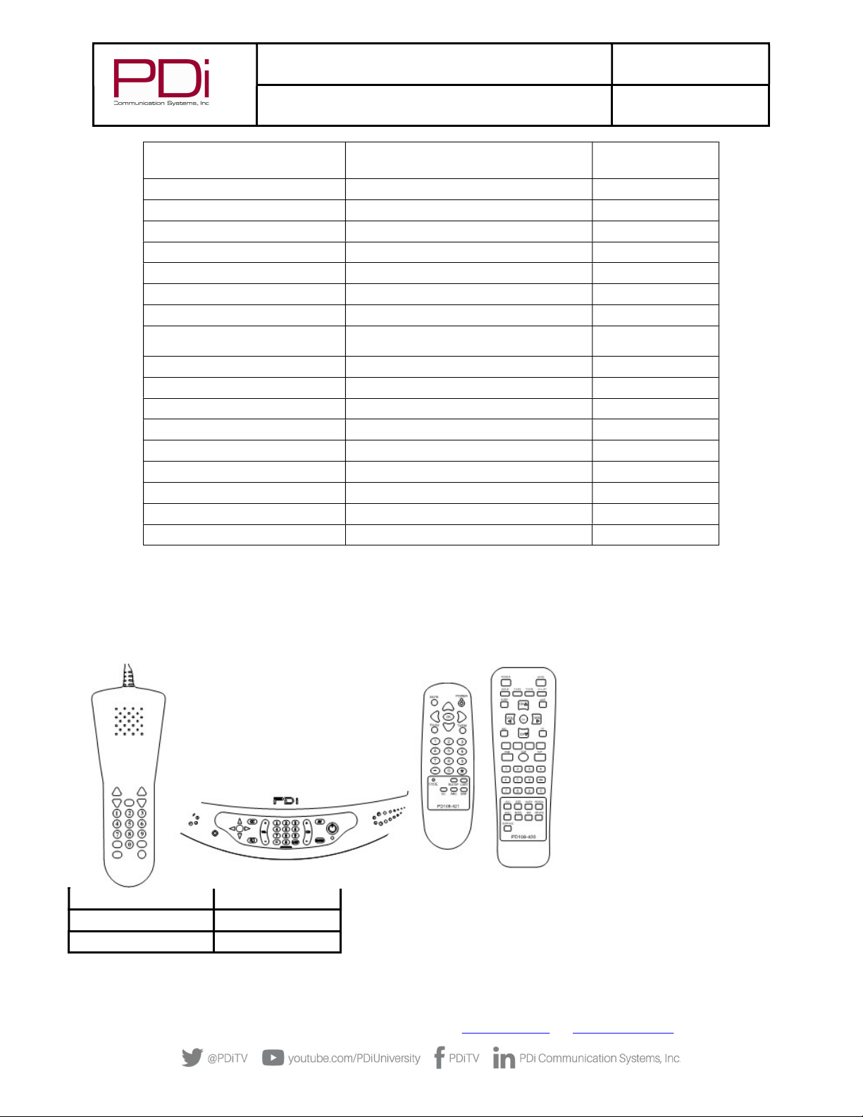
Keypad Programming (Mapping) Instructions
The set-top-box (STB) can be controlled remotely by any of the following that incorporate a keypad: Pillow Speaker, TV’s Keypad
(Arm Mounted TV’s), or Handheld Remote Control. In other words, any control device that incorporates a keypad capable of
controlling the TV can also control the set-top-box.
Keypad Programming or Mapping
involves assigning key functions to the
corresponding set-top-box (STB)
functions. It is common practice to
designate a control button to activate the
STB’s Channel “Guide” feature. This
feature allows for quicker selection of
satellite channels. Some common control
buttons used for “Guide” are listed
below. Your installation may vary
depending upon the control device’s
availability of these particular buttons.
Control
Button
STB
Function
Menu
Guide
(-)
Guide
1. Enter the Interface Module Setup Menu (See “Understanding Interface Module Setup Menus” earlier in this manual).
2. Select menu pages 1 through 5.
3. For each “TV Key” on the left column, set the matching “STB COMMAND” on the right column to the desired STB function.

MODEL:
PDi BELLA-HD Interface
Document Number:
PD196-426R1
User Manual Page 19 of 27
PDi Communication Systems, Inc. ▪ 40 Greenwood Ln ▪ Springboro, Ohio 45066 USA ▪ www.PDiarm.com and www.mymedTV.com ▪ Phone 800.628.9870
Programming for Off-Air Non-Satellite Channels Using Off-Air RF Pass-Thru
The set-top-box (STB) can be remotely turned off, which allows any signal connected to the “OFF-AIR” input of the STB to be active
and then viewed downstream by the TV. The Off-Air signal could be a DVD player for an in-house movie channel, an externally
connected antenna for local over-the-air channels, or cable TV channels. See pages 7 or 8 for details regarding connection of an Off-Air
signal.
NOTE: Off-Air signals are optional and may not be available at the facility. Some set-top-boxes do not have off air pass
through. In either case this instruction section may be skipped.
To view an Off-Air signal, the patient must turn Off the STB. A control key must be assigned to perform this function. The control key
should NOT be the TV’s POWER button as it is used to power the TV On and Off. Instead, another key must be selected. Below are some
suggestions for STB “Power” keys that might be utilized on some common control devices.
CONTROL
DEVICE
SUGGESTED
CONTROL
KEY
Pillow
Speaker
ALT,
MENU, TV/AV
TV
Keypad
MENU, OK, AV
Remote
TV/AV, ( - )
An Example for Off-Air RF Pass-Thru
A facility has an outside antenna that contains several local TV channels that they wish to provide to their patients for viewing in
addition to Satellite TV channels.
The facility is equipped with the PDI-P15X arm mounted television powered remotely from a central style power supply. The Off-Air
antenna signal is connected to the input of the central power supply and the STB is connected using the Optional Secondary RF Coax
cable as shown on pages 8 and 9.
For this configuration, the yellow (Menu) button on the TV’s keypad is chosen to Power the STB on and off by changing the mapping of
the TV “Menu” key to “Power”.
Now, Exit the Interface Module SETUP menu by pressing the SETUP button on the
programming remote.
Pressing the “MENU” button on the TV’s keypad should power the STB on and off with each key press. The only remaining setup
involves programming the TV for the Off-Air channels while the STB is off. The TV’s channel programming is not required to include
the STB’s channel as well. For example, if the STB is set for channel 3 output, the same channel could be omitted from the TV’s channel
table, if no local channel 3 is available. Please see the programming instructions specific to the model PDi TV being used.
STB INTERFACE SETUP
-TV KEY- -STB COMMAND-
Up Arrow Up Arrow
Dn Arrow Down Arrow
Lt Arrow Left Arrow
Rt Arrow Right Arrow
Menu Power
Home
Guide Guide
Info Info
Recall/Star ( * ) Prev Channel
Exit: Exit
Back (Nav) Back
Return: SETUP/OK/LAST

MODEL:
PDi BELLA-HD Interface
Document Number:
PD196-426R1
User Manual Page 20 of 27
PDi Communication Systems, Inc. ▪ 40 Greenwood Ln ▪ Springboro, Ohio 45066 USA ▪ www.PDiarm.com and www.mymedTV.com ▪ Phone 800.628.9870
Programming the STB Signal Input Type
The Interface Module must be programmed so that it knows which TV
source input needs the keys to be mapped to the STB. When any other
signal source is selected, all keys will operate normally.
1. Enter the Interface Module Setup Menu (see “Understanding
Interface Module Setup Menus” earlier in this manual)
2. Select menu “Interface Module SETUP 6/6”.
3. Set “STB Signal Input” to match the connection to the STB.
This is usually Tuner but may be “HDMI” or “Component” for
high-definition STB’s.
4. If “STB Signal Input” is “Tuner” then set the “STB Channel” to
match the STB’s modulated RF output. The illustration depicts
the channel as number 3 in this example.
5. Exit setup. Verify the STB signal is now displayed on the television.
Restoring Factory Default Settings
The Interface Module configuration can be reset to factory defaults. Resetting to defaults
cannot be undone. If the Interface is connected to a PDI-P19W the default configuration will
be optimized for the P19W’s keypad. It will not match the settings that came preloaded onto
the Interface.
1. Enter the Interface Module Setup Menu (See “Understanding Interface Module
Setup Menus” earlier in this manual).
2. Select menu “Interface Module SETUP 6/6”.
3. Highlight the “Restore Factory Defaults” item.
4. Press “VOL►” to restore factory defaults. The operation will happen immediately
and cannot be undone.
Operation
PDi Interface Module operation is straight forward once configured. Site installations that involve a secondary “Off Air” signal require
additional instruction to provide a worry-free patient viewing experience.
Cable/Satellite TV Operation
1. Turn the TV on. A channel from the set-top-box should be displayed.
2. Channel the TV Up or Down. The set-top-box channel should follow.
3. Press the designated Guide button or press “00”. A channel guide should appear.
4. Select a channel from the Guide. The viewed set-top-box channel should follow the selection.
INTERFACE MODULE SETUP
TV Input For STB Tuner
TV Chan For STB 003
STB Model DC50X
Restore Defaults for STB >
Flash Intface Pwr LED Off
Power Save On
DIAGNOSTICS
IR Interface F/W Ver V5.00
TV CCI Ver V4.6
IR Cable Connected
Return
: SETUP
/OK/LAST
INTERFACE MODULE SETUP 6/6
TV Input For STB Tuner
TV Chan For STB 003
STB Model DC50X
Restore Defaults for STB >
Flash Interface Pwr LED Off
Power Save On
DIAGNOSTICS
IR Interface F/W Ver V5.00
TV CCI Ver V4.6
IR Cable Connected
Return: SETUP/OK/LAST
Table of contents
Other PDi Control Unit manuals


Popular Control Unit manuals by other brands


Chamberlain
Chamberlain CAPXLCAM Instructions for installing

Telit Wireless Solutions
Telit Wireless Solutions SE868K A Series Product user guide

IBP
IBP HDC75 Quick start guide and safety instructions

Quonset Microwave
Quonset Microwave QM2010-10-20 manual

Vertiv
Vertiv NetSure M831A user manual

EnOcean
EnOcean STM 329 user manual

Idex
Idex Liquid Controls F Series Installation-Parts

Apollo Valves
Apollo Valves 61YLF Series Installation, operation, maintenance guide

Extron electronics
Extron electronics TLP 350MV Setup guide

AMX
AMX RMX 16 installation guide

Pfeiffer Vacuum
Pfeiffer Vacuum DCU 002 operating instructions

PalmSens
PalmSens EmStat3+ Getting started