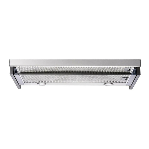
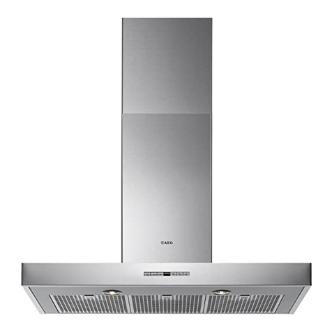
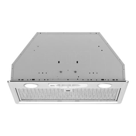
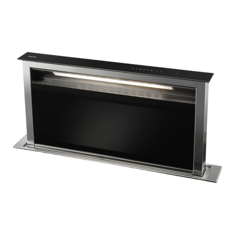
AEG DD9963-M User manual

DD9963-M DD9993-M
Einbau-Flachschirm-Dunstabzugshaube
Built-In- Flat-Screen Fume Extractor Hood
Inbouw-wasemkappen met plat scherm
Cappa aspirante da incasso con schermo piatto Estraibile
Utsugande köksfläkt för inbyggnad med platt utdragbar skärm
Innebygget kjøkkenvifte (sugeversjon) med flat uttrekkbar skjerm
Emhætte til indbygning med flad, udtagelig skærm
Keittiökaapistoon asennettava etulevyllinen poistoilmatuuletin
Montage- und Gebrauchsanweisung
Installation and Operating Instructions
Montage- en gebruiksaanwijzing
Istruzioni di montaggio e per l'uso
Anvisningar för montering och användning
Instruksjoner for montering og bruk
Monterings- og brugsanvisninger
Asennus- ja käyttöohjeet

2
2
INHALTSVERZEICHNIS
EMPFEHLUNGEN UND HINWEISE......................................................................................................................................4
CHARAKTERISTIKEN............................................................................................................................................................5
MONTAGE..............................................................................................................................................................................7
BEDIENUNG.........................................................................................................................................................................10
WARTUNG............................................................................................................................................................................11
INDEX
RECOMMENDATIONS AND SUGGESTIONS....................................................................................................................13
CHARACTERISTICS............................................................................................................................................................14
INSTALLATION....................................................................................................................................................................16
USE.......................................................................................................................................................................................19
MAINTENANCE....................................................................................................................................................................20
INHOUDSOPGAVE
ADVIEZEN EN SUGGESTIES.............................................................................................................................................22
EIGENSCHAPPEN...............................................................................................................................................................23
INSTALLATIE.......................................................................................................................................................................25
GEBRUIK..............................................................................................................................................................................28
ONDERHOUD ......................................................................................................................................................................29
INDICE
CONSIGLI E SUGGERIMENTI............................................................................................................................................31
CARATTERISTICHE............................................................................................................................................................32
INSTALLAZIONE..................................................................................................................................................................34
USO ......................................................................................................................................................................................37
MANUTENZIONE.................................................................................................................................................................38
INNEHÅLL
REKOMMENDATIONER OCH TIPS....................................................................................................................................40
EGENSKAPER.....................................................................................................................................................................41
INSTALLATION....................................................................................................................................................................43
ANVÄNDING.........................................................................................................................................................................46
UNDERHÅLL........................................................................................................................................................................47
INNHOLD
ANBEFALINGER OG FORSLAG.........................................................................................................................................49
EGENSKAPER.....................................................................................................................................................................50
INSTALLASJON...................................................................................................................................................................52
BRUK....................................................................................................................................................................................55
VEDLIKEHOLD.....................................................................................................................................................................56
DE
EN
NL
IT
SE
NO

3
3
INDHOLD
RÅD OG ANVISNINGER......................................................................................................................................................58
APPARATBESKRIVELSE....................................................................................................................................................59
INSTALLATION....................................................................................................................................................................61
BRUG....................................................................................................................................................................................64
VEDLIGEHOLDELSE...........................................................................................................................................................65
SISÄLTÖ
OHJEET JA SUOSITUKSET................................................................................................................................................67
MITAT JA OSAT...................................................................................................................................................................68
ASENNUS.............................................................................................................................................................................70
KÄYTTÖ................................................................................................................................................................................73
HUOLTO...............................................................................................................................................................................74
DK
FI

DE
4
4
EMPFEHLUNGEN UND HINWEISE
Diese Gebrauchsanleitung gilt für mehrere Geräte-Ausführungen.
Es ist möglich, dass einzelne Ausstattungsmerkmale beschrieben sind, die nichtauf
Ihr Gerät zutreffen.
FÜR DEN KÜCHENMÖBEL-MONTEUR
• Der Hersteller haftet nicht für Schäden, die auf eine fehlerhafte und unsachgemäße
Montage zurückzuführen sind.
• Der Sicherheitsabstand zwischen Kochmulde und Haube muss mindestens 650 mm
betragen.
• Prüfen, ob die Netzspannung mit dem Wert auf dem im Haubeninneren angebrach-
ten Schild übereinstimmt.
• Das Abluftrohr der Haube muss bei Abluftbetrieb einen Durchmesser von Mindes-
tens 120 mm aufweisen.Die Abluftstrecke muss so kurz wie möglich sein.
• Die Haube darf nicht in einen Rauch- oder Abgasschornstein eingeleitet werden.
• Der gemeinsame gefahrlose Betrieb von kamingebundenen Geräten und Dunstab-
zugshauben ist nur gewährleistet, wenn Raum und/oder Wohnung durch eine ge-
eignete Zuluftöffnung von ca.500-600cm2von außen belüftet sind.
FÜR DEN BENUTZER
• Die Dunstabzugshaube istausschließlich zum Einsatz im privaten Haushalt und zur
Beseitigung von Küchengerüchen vorgesehen.
• UnsachgemäßerEinsatz der Haube ist zu unterlassen.
• Kochstellen müssen bei Betrieb stets abgedeckt sein. Unbedingt zu vermeiden sind
offene Feuerstellen bei Öl-, Gas- und Kohleherden.
• Frittiergeräte müssen während des Gebrauchs stets beaufsichtigt werden: überhitz-
tes Öl kann sich entzünden.
• Keine flambierten Speisen unter der Abzugshaubezubereiten: Brandgefahr.
• Dieses Gerät darf nicht von Personen, auch Kindern, mit verminderten psychischen,
sensorischen und geistigern Fähigkeiten, oder von Personen ohne Erfahrung und
Kenntnisse benutzt werden, sofern sie nicht von für ihre Sicherheit verantwortlichen
Personen beaufsichtigt und beim Gebrauch des Geräts angeleitet werden.
• Kinder dürfen sich nicht unbeaufsichtigt in der Nähe des Geräts aufhalten und auf
keinen Fall mit dem Gerät spielen.
WARTUNG
• Bevor Wartungsarbeiten durchgeführt werden, muss die Stromzufuhr zur Haube
unterbrochen werden, indem der Stecker gezogen oder der Hauptschalter abge-
schaltet wird.
• Bei der Filterwartung müssen die vom Hersteller empfohlenen Zeiträume zum Aus-
tauschen der Filter genauestens eingehalten werden.
• Zur Reinigung der Haubenfläche empfehlen wir ein feuchtes Tuch und mildes
Spülmittel.
Das Symbol auf dem Produkt oder seiner Verpackung weist darauf hin, dass dieses Produkt
nicht als normaler Haushaltsabfall zu behandeln ist, sondern an einem Sammelpunkt für das Recyc-
ling von elektrischen und elektronischen Geräten abgegeben werden muss.Durch Ihren Beitrag zum
korrekten Entsorgen dieses Produkts schützen Sie die Umwelt und die Gesundheit Ihrer Mitmen-
schen. Umwelt und Gesundheit werden durch falsches Entsorgen gefährdet. Weitere Informationen
über das Recycling dieses Produkts erhalten Sie von Ihrem Rathaus, Ihrer Müllabfuhr oder dem
Geschäft, in dem Sie das Produkt gekaufthaben.
DE
5
5
CHARAKTERISTIKEN
Komponenten
Pos. St. Produktkomponenten
11 Haubenkörper mit Schaltern, Beleuchtung, Gebläsegruppe, Filter
2.1 1 oberer Kaminteil
2.2 1 unterer Kaminteil
91 Flansch
16 1 Filterdeckel
Pos. St. Montagekomponenten
7.2.1 2 Befestigungsbügel oberer Kaminteil
11 6 Dübel
11a 2 Dübel SB 12/10
12a 6 Schrauben 4,2 x 44,4
12c 10 Schrauben 2,9 x 6,5
St. Dokumentation
1 Bedienungsanleitung
2.1
2.2
12c
12a 7.2.1 11
16
1
9
11
12a
12c
11a

DE
6
6
Platzbedarf

DE
7
7
11
22
150
11a
11
12a
YY
1090 X
1÷2
7.2.1
150
820
MONTAGE Bohren der Wand und Befestigung der Bügel
Bei Montage der Haube in Umluftversion darauf achten, dass oberhalb der Haube ein Abstand von
mindestens 8-10 cm zur oberen Begrenzung (Decke oder Brett) einzuhalten ist.
An der Wand anzeichnen:
• eine senkrechte Linie bis zur Decke oder zum oberen Rand in der Mitte des Installationsbereichs der Hau-
be.
• eine waagrechte Linie mindestens 1090 mm oberhalb der Kochmulde.
• Ymm rechts von der senkrechten Bezugslinie einen Punkt (1) auf der waagrechten Linie kennzeichnen.
• Diesen Vorgang an der gegenüberliegenden Seite wiederholen und die Ausrichtung überprüfen.
• Wie angegeben 150 mm rechts von der senkrechten Bezugslinie und 820 mm oberhalb der Kochmulde
einen Punkt (2) kennzeichnen.
• Diesen Vorgang an der gegenüberliegenden Seite wiederholen und die Ausrichtung überprüfen.
• Die gekennzeichneten Punkte (1) mit einem Bohrer ø 12 mm bohren.
• Die gekennzeichneten Punkte (2) mit einem Bohrer ø 8 mm bohren.
• Die Dübel mit dem Bügel 11a in die Bohrungen (1) einfügen und festschrauben.
• Den Dübel 11 in die Bohrungen (2) einfügen.
• Den Bügel 7.2.1 wie angegeben 1-2 mm unterhalb der Decke oder der oberen Begrenzung anlegen und
seinen Mittelpunkt (Einschnitte) an der senkrechten Bezugslinie ausrichten.
• Die Mitte der Löcher des Bügels kennzeichnen.
• Den Bügel 7.2.1 wie angegeben X mm unterhalb des ersten Bügels (X = Höhe des mitgelieferten oberen
Kaminteils) anlegen und seinen Mittelpunkt (Einschnitte) an der senkrechten Bezugslinie ausrichten.
• Die Mitte der Löcher des Bügels kennzeichnen.
• Die gekennzeichneten Punkte mit einem Bohrer ø 8 mm bohren.
• Die Dübel 11 in die Bohrungen einfügen.
• Die Bügel mit den mitgelieferten Schrauben 12a (4,2 x 44,4) fixieren.
Haubentyp 60 90
Y 200 350

DE
8
8
Montage des Haubenkörpers
• Die Platte vom Haubenkörper aushaken, indem der
Hebel des Befestigungsstiftes verschoben wird.
• Die beiden Schrauben Vr der Bügel 11a so regulie-
ren, dass sie nur bis zum Gewindebeginn einge-
schraubt sind.
• Den Haubenkörper bei den 2 Bügeln 11a einhaken.
• Vom Haubeninneren her den Haubenkörper mit Hilfe
der Schrauben Vr ausrichten.
• Die Sicherheitsschraube 12a festziehen.
11
12a
Vr
11a
Anschlüss in abluftversion
Bei Abluftbetrieb kann die Haube vom Installateur
wahlweise mittels Rohr oder Schlauch (ø 150 oder 120
mm) an die Außenrohrleitung angeschlossen werden.
• Bei Verwendung eines Anschlussrohres ø 120 den
Reduzierflansch 9am Haubenaustritt anbringen.
• Das Rohr mit geeigneten Rohrschellen fixieren. Das
hierzu erforderliche Material wird nicht mitgeliefert.
• Eventuell vorhandene Aktivkohlefilter entnehmen.
ø 150
9
ø 120
ANSCHLUSS IN UMLUFTVERSION
Für die Installation in Umluftversion muss das optiona-
le Kit „Aktivkohle-Filtereinsatz“ erworben werden.
• Das Winkelstück der Kaminbefestigung entfernen
• Den Filterdeckel am Luftausgang mit den vier
Schrauben 12c (2,9 x 6,5) fixieren.
16
12c
8
12e

DE
9
9
Kaminmontage
Der Kamin Kann nur bei der Haube in der Abluftausführung an-
gebracht werden.
Oberer Kaminteil
• Die beiden seitlichen Schenkel leicht auseinanderbiegen, hinter
den Bügeln 7.2.1 einhängen und bis zum Anschlag wieder
schließen.
• Bei den Bügeln mit Hilfe der 4 mitgelieferten Schrauben 12c
fixieren.
Unterer Kaminteil
• Die beiden seitlichen Schenkel des Kaminteils leicht auseinan-
derbiegen, zwischen dem oberen Kaminteil und der Wand ein-
hängen und bis zum Anschlag wieder schließen.
• Den unteren Teil seitlich am Haubenkörper mit 2 der mitgelie-
ferten Schrauben 12c fixieren.
12c
2.1
2.2
2
7.2.1
12c
ELEKTROANSCHLUSS
• Bei Anschluss der Haube an das Stromnetz muss ein zweipoli-
ger Schalter mit einem Öffnungsweg von mindestens 3 mm
zwischengeschaltet werden.
• Entfernen Sie die Fettfilter (s. Abschnitt „Wartung“) und versi-
chern Sie sich, daß die Kabelverbindung in die Steckdose des
Gebläses einwandfrei eingesteckt wird.

DE
1
0
10
BEDIENUNG
Schalttafel
Taste
Funktion LED
A Schaltet die Beleuchtung ein oder aus. -
B Schaltet die verminderte Beleuchtung ein oder
aus. -
C Schaltet den Motor der Absauganlage bei der
zuletzt verwendeten Geschwindigkeit ein und
aus.
Die LEDs schalten sich je nach Geschwindig-
keitseinstellung ein oder aus.
Gebläsestufe 1, LED V1 an.
Gebläsestufe 2, LED V1 + V2 an.
Gebläsestufe 3, LED V1 + V2 + V3 an.
D Erhöht die Betriebsgeschwindigkeit. -
E Vermindert die Betriebsgeschwindigkeit. -
F Aktiviert von jeder Geschwindigkeit aus, auch
bei abgestelltem Motor, die Intensivgeschwin-
digkeit, die auf 5 Minuten zeitgeregelt ist.
Nach Ablauf dieser Zeit kehrt das System zu
der zuvor eingestellten Geschwindigkeit zu-
rück. Für die Beseitigung von sehr intensiven
Kochdünsten geeignet.
Wird durch Betätigen der Taste oder Abstellen
des Motors deaktiviert.
Die LED Fschaltet sich ein.
G Aktiviert bei der dritten Geschwindigkeitsstufe
das um 10’, bei der zweiten Stufe das um 15’
und bei der ersten Stufe das um 20’ verzögerte
automatische Abstellen des Motors und der
Beleuchtung. Zur Beseitigung von Restgerü-
chen geeignet; wird durch Betätigen der Taste
oder Abstellen des Motors deaktiviert.
Die LED Gschaltet sich ein.
H Fügt ein Reset des Alarms für Filtersättigung
aus, sofern diese angezeigt wird.
Nach 100 Betriebsstunden zeigt die bleibend
eingeschaltete LED Hdie Sättigung der Me-
tallfilter an.
Nach 200 Betriebsstunden zeigt die blinkende
LED Hdie Sättigung der Aktivkohlefilter an.
Achtung: auf die Symbol druecken, um das Geraet zu bedien
A B C D E F G H
Led V1 V2 V3 F G H

DE
1
1
11
WARTUNG
Metallfettfilter
REINIGUNG DER SELBSTTRAGENDEN METALLFETTFILTER
Reset des Alarmsignals
• Die Beleuchtung und den Abzugsmotor abstellen.
• Die Taste H drücken.
Reinigung der Filter
• Die Fettfilter sind spülmaschinengeeignet und müssen gewa-
schen werden, sobald sich die LED H einschaltet, oder
mindestens alle 2 Monate, oder auch öfter, je nach Intensität
des Gebrauchs.
• Die Filter einen nach dem andern ausbauen, dabei mit einer
Hand festhalten und mit der anderen Hand den Hebel nach un-
ten ziehen.
• Die Filter waschen, ohne sie zu verbiegen, und vor dem
erneuten Einbau trocknen lassen.
• Nun die Filter wieder einbauen, so dass der Griff nach der
äußeren Sichtseite zeigt.

DE
1
2
12
Aktivkohle-Geruchsfilter (Filterversion)
Der Aktivkohlefilter ist weder waschbar, noch regenerierbar und muss ausgewechselt werden,
wenn die LED Hblinkt, oder mindestens alle 4 Monate. Die Alarmmeldung erfolgt nur, wenn
der Absaugmotor zugeschaltet ist.
Aktivierung des Alarmsignals
• Bei den Filterversionen der Abzugshauben wird die Alarmanzeige für Filtersättigung im
Augenblick der Installation oder in der Folge aktiviert.
• Die Beleuchtung und den Absaugmotor abstellen.
• Die Taste Gdrücken.
• Innerhalb von 5 Sekunden die Taste Hdrücken, bis die LED Hzur Bestätigung blinkt:
• 2 Mal blinken der LED – Alarm wegen Sättigung des Aktivkohlefilters AKTIVIERT.
• 1 Mal blinken der LED – Alarm wegen Sättigung des Aktivkohlefilters DEAKTIVIERT.
Auswechseln des Aktivkohle-Geruchsfilters
Reset des Alarmsignals
• Die Beleuchtung und den Absaugmotor abstellen.
• Die Taste H drücken.
Auswechseln des Filters
• Die Fettfilter aus Metall entfernen.
• Die verbrauchten Aktivkohle-Geruchsfilter wie angegeben
ausbauen (A).
• Die neuen Filter wie angegeben einbauen (B).
• Die Fettfilter aus Metall wieder einbauen.
A
B
Beleuchtung
AUSWECHSELN DER LAMPEN
Halogenlampe 20 W
• Vor dem Auswechseln der Lampen, die beiden Schrauben der
Lampenhalterung loesen und die Lampenhalterung aus der
Dunstabzugshaube ziehen.
• Die Lampe aus der Halterung nehmen.
• Die Lampe durch eine gleichwertige ersetzen und bei der Re-
montage darauf achten, daß die beiden Steckerstifte vor-
schriftsmäßig in die Lampenfassung eingeführt werden.
• Die Lampenhalterung wieder montieren, indem die beiden zu-
vor entfernten Schrauben wieder angezogen werden.

EN
1
3
13
RECOMMENDATIONS AND SUGGESTIONS
The Instructions for Use apply to several versions of this appliance. Accor
d-
ingly, you may find descriptionsof individual features that do not apply to your
specific appliance.
INSTALLATION
• The manufacturer will not be held liable for any damages resulting from incor-
rect or improper installation.
• The minimum safety distance between the cooker top and the extractor hood
is 650 mm.
• Check that the mains voltage corresponds to that indicated on the rating plate
fixed to the insideof the hood.
• For Class I appliances, check that the domestic power supply guarantees ade-
quateearthing.
Connect the extractor to the exhaust flue through a pipe of minimum diameter
120 mm.The route of the flue must be asshort as possible.
• Do not connect the extractor hood to exhaust ducts carrying combustion fumes
(boilers, fireplaces, etc.).
• If the extractor is used in conjunction with non-electrical appliances (e.g. gas
burning appliances), a sufficient degree of aeration must be guaranteed in the
room in order to prevent the backflow of exhaust gas. The kitchen must have
an opening communicating directly with the open air in order to guarantee the
entry of clean air.
USE
• The extractor hood has been designed exclusively for domestic use to elimi-
nate kitchen smells.
• Never use the hood forpurposesotherthan for which ithas ben designed.
• Never leave high naked flames under the hood when it is in operation.
• Adjust the flame intensity to direct it onto the bottom of the pan only, making
sure that it does not engulf the sides.
• Deep fat fryers must be continuously monitored during use: overheated oil can
burst into flames.
• Do not flambè under the range hood; risk of fire
• This appliance is not intended for use by persons (including children) with re-
duced physical, sensory or mental capabilities, or lack of experience and
knowledge, unless they have been given supervision or instruction concerning
use of the appliance by a person responsible for their safety.
• Children should be supervised to ensure that they do not play with the appli-
ance.
MAINTENANCE
• Switch off or unplug the appliance from the mains supply before carrying out
any maintenance work.
• Clean and/or replace theFilters after the specified time period.
• Clean the hoodusinga damp cloth and a neutral liquid detergent.
The symbol on the product or on its packaging indicates that this product may not be
treated as household waste. Instead it shall be handed over to the applicable collection point
for the recycling of electrical and electronic equipment. By ensuring this product is disposed
of correctly, you will help prevent potential negative consequences for the environment and
human health, which could otherwise be caused by inappropriate waste handling of this
product. For more detailed information about recycling of this product, please contact your
local city office, your household waste disposal service or the shop where you purchased the
product.

EN
1
4
14
CHARACTERISTICS
Components
Ref. Q.ty Product Components
1 1 Hood Body, complete with: Controls, Light, Blower, Filters
2.1 1 Upper Section
2.2 1 Lower Section
9 1 Flange
16 1 Filter cover
Ref. Q.ty Installation Components
7.2.1 2 Upper Chimney Section Fixing Brackets
11 6 Wall Plugs
11a 2 Wall Plugs SB 12/10
12a 6 Screws 4,2 x 44,4
12c 10 Screws2,9 x6,5
Q.ty Documentation
1 Instruction Manual
2.1
2.2
12c
12a 7.2.1 11
16
1
9
11
12a
12c
11a

EN
1
5
15
Dimensions

EN
1
6
16
11
22
150
11a
11
12a
YY
1090 X
1÷2
7.2.1
150
820
TypeHood 60 90
Y 200 350
INSTALLATION Wall drilling and bracket fixing
When installing the hood in recycling version it has to be taken into consideration that space re-
maining between the hood and the upper limit (ceiling or self) is at least 8-10 cm.
As a first step, proceed with the following drawings:
• a vertical line up to the ceiling or up to the upper limit, at the centre of the area in which the hood is to
be fitted;
• a horizontal line at a minimum 1090 mm above the cooker top.
• Mark a point (1) on the horizontal line, Ymm to the right of the vertical reference line.
• Repeat this operation on the other side, checking that the two marks are levelled.
• Mark a reference point (2) as indicated at 150 mm from the vertical reference line and 820 mm above
the cooker top.
• Repeat this operation on the other side, checking that the two marks are levelled.
• Drill at the marked points (1), using a ø 12 mm drill bit.
• Drill at the marked points (2), using a ø 8 mm drill bit.
• Insert the bracket plugs 11a into the holes (1) and tighten the screws.
• Insert plug 11 into holes (2).
• Place bracket 7.2.1 on the wall, about 1-2 mm from the ceiling or from the upper limit, aligning the cen-
tre (notch) with the vertical reference line.
• Mark the wall at the centres of the bracket holes.
• Place the bracket 7.2.1 on the wall at X mm below the first bracket (X = height of the upper chimney
section), aligning the centre (notch) with the vertical line.
• Mark the wall at the centres of the bracket holes.
• Drill ø 8 mm holes at all the marked centre points.
• Insert the wall plugs 11 in the holes.
• Fix the brackets using the 12a screws (4,2 x 44,4) supplied with the hood.

EN
1
7
17
Mounting the hood body
• Remove the metal grease filters by turning the han-
dles provided.
• Adjust the two screws Vr, on brackets 11a, to a mini-
mum.
• Hook the hood canopy onto the two brackets 11a.
• From inside the hood canopy, adjust the screws Vr to
set the Hood Canopy level.
• Tighten the safety screws 12a.
11
12a
Vr
11a
Connections
DUCTED VERSION AIR EXHAUST SYSTEM
When installing the ducted version, connect the hood to
the chimney using either a flexible or rigid pipe ø 150
or 120 mm, the choice of which is left to the installer.
• To install a ø 120 mm air exhaust connection, insert
the reducer flange 9on the hood body outlet.
• Fix the pipe in position using sufficient pipe clamps
(not supplied).
• Remove possible charcoal filters.
ø 150
9
ø 120
RECYCLING VERSION AIR OUTLET
To install the hood in recycling version, the optional
charcoal filter kit must be purchased.
• Remove the chimney angle bracket.
• Screw the filter cover onto the air outlet, using four
screws 12c (2.9 x 12.5).
16
12c
8
12e

EN
1
8
18
Flue assembly
The chimney can only be installed with exhausting hood.
Upper exhaust flue
• Slightly widen the two sides of the upper flue and hook them
behind the brackets 7.2.1, making sure that they are well
seated.
• Secure the sides to the brackets using the 4 screws 12c (2,9 x
6,5) supplied.
Lower exhaust flue
• Slightly widen the two sides of the flue and hook them be-
tween the upper flue and the wall, making sure that they are
well seated.
• Fix the lower part laterally to the hood body using the 2 screws
12c (2,9 x 6,5) supplied.
12c
2.1
2.2
2
7.2.1
12c
ELECTRICAL CONNECTION
• Connect the hood to the mains through a two-pole switch hav-
ing a contact gap of at least 3 mm.
• Remove the grease filters (see paragraph Maintenance) being
sure that the connector of the feeding cable is correctly inserted
in the socket placed on the side of the fan.

EN
1
9
19
USE
Control panel
Button Function LED
A Turns the lighting system on and off. -
B Turns the reduced intensity lighting system on
and off. -
C Turns the suction motor on and off at the last
speed used. The LEDs turn on and off according to the
speed set.
Speed 1, Led V1 on.
Speed 2, Led V1+V2 on.
Speed 3, Led V1+V2+V3 on.
D Increase the working speed. -
E Decrease the working speed. -
F Activates intensive speed from any other speed
or with the motor off. This speed is timed to
run for 5 minutes, after which the system re-
turns to the previous speed. Suitable to deal
with maximum cooking fumes.
Disabled by pressing the Button or turning the
Motor off.
Led Flights up.
G Activates automatic delayed shutdown of the
Motor and the Lighting System after 10’ if
Speed Three is set, after 15’ if Speed Two is
set, after 20’ if Speed One is set. Suitable to
complete elimination of residual fumes. Dis-
abled by pressing the button or turning the mo-
tor off.
Led Glights up.
H Resets the Filter saturation alarm, if indicated.
After 100 Working Hours, Led Hlights up
Fixed to indicate saturation of the Metal
Grease filters
After 200 Working Hours, Led Hflashes to
indicate saturation of the Activated Char-
coal Filters.
Warning: In order to activate the function press on the symbol
A B C D E F G H
Led V1 V2 V3 F G H

EN
2
0
20
MAINTENANCE
Metal grease filters
CLEANING THE SELF-BEARING METAL GREASE FILTERS
Resetting the alarm signal
• Turn the Lights and the Suction Motor off.
• Press button H.
Cleaning the Filters
• These can be washed in the dishwasher, and need to be cleaned
whenever the HLed comes on or at least once every 2 months
use, or more frequently if use is particularly intensive.
• Remove the Filters one at a time, supporting them with one
hand while you pull the lever down with the other.
• Wash the Filters without bending them, and leave them to dry
completely before replacing.
• Replace, taking care to ensure that the handle faces forwards.
This manual suits for next models
1
Table of contents
Languages:
Other AEG Ventilation Hood manuals
Popular Ventilation Hood manuals by other brands

Bertazzoni
Bertazzoni KU24 PRO 1X installation instructions

Electrolux
Electrolux RS-600 Installation and user manual

Atag
Atag ES9111EM Instructions for use

Dake
Dake Atmos Installation, Use and Maintenance Instruction

Beko
Beko CCB 5140 XA user manual

Imperial
Imperial Slim Line Series Installation instructions & warranty information