AEI Security & Communications SOLARGUARD SG4000 User manual

SolarGuard™ SG4000
Dial Up Alarm System
USER GUIDE
TO INSTALL THIS ALARM PLEASE FOLLOW
THE STEP BY STEP GUIDE IN PAGE ORDER.
AEI SECURITY & COMMUNICATIONS LTD
Weslake Industrial Park
Rye Harbour Road
Rye
East Sussex
TN31 7TE
United Kingdom
Head Office: +44 (0) 1797 226122
Fax: +44 (0) 1797 227122
Email: sales@aeisecurity.com
Helpline (UK): 0845 1667940
Email: support@aeisecurity.com

Page 2
Installation Guide
Table of Contents
PAGE CONTENTS
3 Introducing the SolarGuard™ series
4,5 STEP 1: Unpacking your SolarGuard™ SG4000
6STEP 2: Installing the Control Panel
7STEP 3: Choosing the Site Code
8,9 STEP 4: Setting the Zone Codes
10,11 STEP 5: Installing the PIR sensor
12 STEP 7: Installing the door contacts
13 STEP 8: Site Code learning from the Pocket Remote
14,15,16 STEP 9: Installing the SolarGuard™ Bell Box
17,18 STEP 10: Learning the control panel to the Wireless Bell Box
19,20 Control Panel Functions
21 - 27 Day to Day operation guide
28 - 33 Configuring your SG4000 Control Panel
28 - 33 Configuring your SG4000 Auto Dialler
37 Expanding your system
38 HELP! Frequently asked questions
39 Notes
IMPORTANT NOTICE.
PLEASE FOLLOW YOUR POWER
TOOLS SAFETY GUIDELINES.
ALWAYS USE AN RCD BREAKER
WITH MAINS POWER TOOLS.
Zone Item / Location
1
2
3
4
5
6
ON
OFF
Notes...
This page is a section where you can fill out your specific information of you SG4000 Alarm
system.
The bottom page shows the Site Code if you wish to change it from default (see ‘site code’
section)
Zone Codes
Site Code
This top box is where you can illustrate the information concerning the zone codes.
for example, Zone 1 = Door Contact (Front door)
Page 39

Page 3
Introducing the
SolarGuard™ SG4000
Congratulations in selecting the SolarGuard™
Wireless Burglar Alarm System. You have
taken a sensible step towards protecting your
family and property. The SolarGuard console
and wireless detectors provide an extremely
easy installation and are amazingly simple to
operate.
The SolarGuard™ Control Panel is the core to
the unique innovation in design of this
product. It features a 2 way dial-up system
that allows you to set the system to call your
mobile or office (4 locations max) when
activated. You can also dial-up your system at
any time and listen in on your property. There
is also a compulsory PIN authorisation
procedure that confirms the high level of
security this system operates.
The SolarGuard™ Bell Box is fully protected
by a tough Polycarbonate UV proof housing.
All electronic components are protected with
moisture repellent material applied during
the manufacturing process to ensure long,
reliable, trouble free operation. Two integral
front and rear tamper switches give
maximum security to the unit. When
activated, the SolarGuard™ sounds a built-in
twin siren system at a powerful 115dB’s and
strobe (optional extra) will flash. The siren
duration is selectable from between 1 and 8
minutes. If it’s allowed to sound for the full
siren duration the strobe will latch and
continue for approximately 20 minutes or
until the system is disarmed.
Q: Can I give additional remote controls to family members/friends etc.?
A: Yes - use part number RM01 (see opposite)
Q: In disarm (UNSET) mode, the alarm sounds when I walk in front of a sensor!
A: You must check the zone settings for the sensor that is activating the alarm. It should be
set to zone 1,2, 3, 4, or 5 for standard operation.
Q: The SolarGuard battery is completely discharged!
A: You can use the quick charge socket in the SolarGuard with a standard AC or DC 12V
mains adapter. This will charge the battery faster than sunlight.
Q: The LED in the PIR detector does not light up!
A: In NORMAL mode, the light will not come on when movement is detected.
Q: I have a sensor which appears to be out of range of the SolarGuard. How can I use it in
my system?
A: Use the range extender ET01-434 in conjunction with your sensor.
Q: How many detectors can be added to the system?
A: As many as you like provided they are situated within radio range of the control panel.
HELP!
Frequently asked questions
Page 38
NEED MORE HELP?
check out our website: www.aeisecurity.com
Alternatively,
you can contact our support department by the following means:
email: support@aeisecurity.com
telephone(UK): 0845 1667940
telephone(Intnl): + 44 1797 226122

Expanding Your System with
Additional Wireless
Accessories
Here we have a selection of extra items to improve your SG4000 Solarguard Alarm
system. They are all available by contacting our sales team with the address & phone
number at the back of this manual.
(Use the product code listed with the images).
Page 37
Remote Control
Give additional family
members remote
controls for your alarm.
PART: RM01-434
Magnetic
Door/Window
Contact
Protect additional
doors and windows.
PART: MT01-434
PIR Movement
Detector
Protect additional areas
around your home.
PART: IR02-434
Smoke Detector
Protect your home and
family against fire.
PART: SD01-434
Range Extender
For protecting remote
areas in your home.
PART: ET01-434
Strobe Upgrade
Adds a bright flashing
light when the alarm is
sounding. High
brightness Xenon
tube.
PART: ST01
SolarGuard™
Dummy Bell Box
Adds an additional low
cost visual deterrent to
your alarm system.
PART: SG1100-434
Page 4
STEP 1
Unpacking your SolarGuard™
Before proceeding to step 2 of the installation, unpack the contents of your SolarGuard alarm
system on to a flat surface - such as a table or workbench.
Although we weigh check every box on the production line, please check the you have all
the items listed below.
You will also require the following tools:
• Power Drill
• 5mm Masonry Bit
• Posidrive Screwdriver
KIT CONTENTS:
1) SolarGuard™ Bell Box
2) Bell box fixing kit
3) PIR Movement Detector, 9V PP3 Battery, PIR mounting bracket (2 piece), 2xWall Plug, 2xScrew
4) PIR Movement Detector, 9V PP3 Battery, PIR mounting bracket (2 piece), 2xWall Plug, 2xScrew
5) Magnetic Door/Window Transmitter, magnet, 12V Battery, 4xWall Plugs, 4xScrew
6) Remote Control, 12V A23 Battery
7) 6V Sealed Lead Acid Bell Box Backup Battery
8) Dial Up Control Panel
9) 3x AA 1.2V Rechargeable Control Panel Backup Battery (may be pre-fitted on some models)
10) Control Panel Fixing Kit
11) Telephone Line Cable
ADDITIONAL CONTENTS:
1) SolarGuard™ Bell Box Drill Guide
2) User Guide (this)

+
1
AA 1.2V
AA 1.2V
AA 1.2V
3
4
2
5
6
7
8
9
10 11
Page 5
Continued...
Check Programmed Settings
This function is used to check the programmed settings. These are one-key operations
utilising the LED to display the current setting.
TO CHECK STORED TELEPHONE NUMBERS
1
Press any of the --
6
keys and the LED will display the current setting.
TO CHECK AUTOMATED DIALING
7
Press any of the key and the LED will display the stored amount of cycles.
TO CHECK ENTRY/EXIT DELAY TIME
8
Press the key and the LED will display the amount of seconds
TO CHECK ALARM SIREN DURATION
9
Press the key and the LED will display the amount in minutes
TO CHECK Remote Call-In Ring Cycle
0
Press the keys and the LED will display the number of ring cycles
TO CHECK LAST ACTIVATED ZONE
#
Press the key and the LED will display the last zone activated from memory
TO CHECK LOW BATTERY STATUS
*
Press the key and the LED will display the zone in which there is a sensor or
detector with a low battery.
Page 36

Continued...
Enter the ‘P’ key
STEP 1
Enter the ‘7’ key.
(command code for this function)
STEP 4
Program Automatic Dialing Codes
Default: 2 Cycles
This function is for users to program the amount of times the system will dial the entire
sequence of programmed phone numbers.
The factory default is set up for 2 cycles. you can program it to run up to 9 times
P
Enter your new (or default) PIN
STEP 2
2 3 41
Wait until the LED displays:
STEP 3
7
Enter a single digit between 0-9 depending of cycles you desire
STEP 5
NOTE: Within a few seconds, you will hear a confirmation tone,
One long beep = correct entry / 3 quick beeps = Incorrect entry
Enter the ‘P’ key
STEP 1
Enter the ‘0’ key.
(command code for this function)
STEP 4
Program Remote Call-In Ring Cycle
Default: 6 Rings
This function is for users to program the amount of rings the system picks up during a
remote call in.
(calling into the system from any location to arm, disarm, monitor or speak) This can be programmed up to 9 rings.
P
Enter your new (or default) PIN
STEP 2
2 3 41
Wait until the LED displays:
STEP 3
0
Enter a single digit between 0-9 depending of cycles you desire ‘
0’ turns Call -In feature OFF
STEP 5
NOTE: Within a few seconds, you will hear a confirmation tone,
One long beep = correct entry / 3 quick beeps = Incorrect entry Page 35
STEP 1
Installing Your Control Panel
Where should I install the control
panel?
Ideally, the control panel should be located
near the front entry/exit. In this position it is
easily accessible on the way in and out.
STEP 1
Mark out 2 points at a distance of 178mm on
the wall.
STEP 2
Drill these 2 holes with a 5mm masonry
drill bit.
STEP 3
Apply the 2 wall plugs supplied into the hole,
ensuring that it slots in securely.
STEP 4
Insert the two remaining screws into the wall
plugs leaving a 7-9mm gap between the wall
plug and the head of the screw.
STEP 5
Using the two pre-drilled holes on the back of
the control panel, it should slot over the two
screws in the wall. Firmly push the control
panel down until it fits securely to the wall.
STEP 6
Apply the power supply
and the telephone
cord to the points
under the control
panel.
NOTE: the supplied AA
back-up battery is not
connected. unscrew the panel
at the front to gain access.
IMPORTANT NOTICE.
PLEASE FOLLOW YOUR POWER
TOOLS SAFETY GUIDELINES.
ALWAYS USE AN RCD BREAKER
WITH MAINS POWER TOOLS.
STEP 2
STEP 1
STEP 5
ADVICE
WE
RECOMMEND
TESTING BEFORE
FULLY
INSTALLING
Page 6

STEP 2
Choosing your site code
What is your site
code?
Your site code is a code set
by you, which identifies
components of your alarm
system. It is set by the first
9 switches located in every
PIR, magnetic door contact
and remote control. Every
device must have the same
setting for the system to
function correctly.
Why have a site code?
The site code is a security
feature which stops
unauthorized persons
disarming your alarm
system with a newly
purchased remote control.
In order for a remote
control to operate your
alarm - the site code in that
remote must be identical
to yours.
Do I need to change
the site code from its
default setting?
No, but we recommend
you change the default
setting as all of our systems
are shipped with the same
site code. Changing the
code will increase the
security offered by your
system.
REMOTE
CONTROL
This has the 9
switches located
under the
battery cover on
the rear of the
device.
PIR
DETECTOR
This device has
12 switches in
total. Switches
1-9 represent
the site code.
MAGNETIC
DOOR
CONTACT
This device has
12 switches in
total. Switches
1-9 represent
the site code.
Page 7
Within a few seconds you will hear a confirmation tone. This confirms that the information
has been stored.
Programming Your SG4000
Auto-Dialer Functions
Enter the
STEP 1
Enter the ‘1’ key to program the first number to be dialed (1-6).
To enter the
second number into the program, simply add the number ‘2’ in the sequence above instead of 1.
STEP 4
Program Auto-Dialer Telephone Numbers
This function allows up to six numbers to be entered into the Auto-dialer. Each of which
will be called in sequence in the event of an alarm activation.
P
Enter your new (or default) PIN
STEP 2
2 3 41
Wait until the LED displays:
STEP 3
STEP 5
Enter the phone number of choice. Only 16 digits are currently authorised and accepted.
NOTE: One long beep = correct entry / 3 quick beeps = Incorrect entry
NOTE: It is recommended to have the Auto-dialer call out to other users,
family members, neighbours etc.
DO NOT program the alarm system to call the emergency services!
If you require calling through an extension to an outside line, for example 9, the system
can add a pause to do this feature.
Simply by adding the ‘star’ key a 2 second pause will be included
for example:
*
9 01424123456 would dial 9, pause for 2 seconds, then dial the next number
(area code followed by the number).
*
STEP 6
1
key
Page 34

Continued...
Enter the
STEP 1
Enter the
STEP 4
Program Door Chime Function
Default: ON
This function allows the door chime sound to be turned On or Off while entering or exiting
during disarming mode
(ALARM OFF MODE)
,
S
Enter your new (or default) PIN
STEP 2
Wait until the LED displays:
STEP 3
5
STEP 5
Within a few seconds you will hear a confirmation tone. This confirms that the information
has been stored.
NOTE: One long beep = correct entry / 3 quick beeps = Incorrect entry
4
Enter the
STEP 1
Enter the
STEP 4
L
Enter your new (or default) PIN
STEP 2
Wait until the LED displays:
STEP 3
STEP 5
Push any button on the Pocket Remote
NOTE: One long beep = correct entry / 3 quick beeps = Incorrect entry
#
CCoonnttiinnuueedd......
2 3 41
2 3 41
Key
key
(command code for this function)
key
key to turn door chime OFF, or enter the key to turn door chime ON
Page 33
What is a Zone Code?
The Zone code sets the
desired behavior of a
sensor. It also enables you
to identify which sensor
has triggered your system
or has a low battery. Every
PIR and magnetic door
contact has a zone setting.
How do I set the Zone
Code?
The code is set by
modifying switches 10,11
and 12 in your PIRs and
door contacts. Please refer
to the table opposite when
setting the zone setting.
NOTICE:
You can skip this
step if you do not
wish to change the
default settings of
your sensors.
i.e. PIR on Instant/
Walk through and
both door contacts
set to Entry/Exit
mode.
STEP 3
Setting the Zone Codes
Key
(page Opposite)
Disarming Mode
Partial arming mode
Arming Mode
Page 8

ZONE 10 11 12 Usage
Zone 1 ON OFF OFF NO YES YES Entry/Exit
A sensor set to Zone 1 will give you a 20
Second entry/exit delay in this area.
used for magnetic door contacts)
Zone 2 OFF ON OFF NO NO YES Instant Walk through
A sensor set to Zone 2 will give you a 20
second entry/exit delay ONLY if a zone 1
sensor has been triggered first. If not, the
sensor will trigger the alarm immediately if
set. Normally used for a PIR in your
entrance
Zone 3 OFF OFF ON NO NO YES Instant
A sensor on Zone 3 will trigger the alarm
immediately if set.
Zone 4 ON ON OFF YES YES Instant
A sensor on Zone 4 will trigger the alarm
immediately wether it is set or not. Normally
used for wireless smoke detectors.
Zone 5 ON OFF ON YES YES Instant
A sensor on Zone 5 will trigger the alarm
immediately wether it is set or not. Normally
used for wireless smoke detectors.
Zone 6 OFF ON ON YES YES 24 Hour Protection
A sensor on Zone 6 will trigger the alarm
immediately wether it is set or not. Normally
used for wireless smoke detectors.
NO
NO
YES
key to turn siren ‘ON
’.
Continued...
Enter the
Enter your new (or default) PIN
Wait until the LED displays:
STEP 1
STEP 2
STEP 3
This function allows users to turn on/off the built in siren in the event of an alarm
situation.
Program Built In Siren
Default: On
S
Enter the
STEP 4
STEP 6
Within a few seconds you will hear a confirmation tone. This confirms that the information
has been stored.
NOTE: One long beep = correct entry / 3 quick beeps = Incorrect entry
STEP 5
Within a few seconds you will hear a confirmation tone. This confirms that the information
has been stored.
NOTE: One long beep = Correct entry / 3 quick beeps = Incorrect entry
Site Code Learning From Pocket Remote
This function allows the Control Panel to ‘learn’ the security system site code. The pocket
remote must be set with the master code, and all other detectors must be set with the same
site code. It is best to use the factory default setting unless absolutely necessary.
PPlleeaasseennoottee::tthheeppoocckkeettrreemmootteeiisstthheeoonnllyyccoommppoonneennttiinntthheessyysstteemmffoorrssiitteeccooddeelleeaarrnniinngg..
TThhiissssttaag
geewwoouullddhhaavveebbeeeennccoommpplleetteeddeeaarrlliieerriinntthhiissmmaannuuaall..TThhiissiissjjuussttffoorrrreeffeerreennccee..
2 3 41
3
2
key
key to turn sound ‘OFF’, or enter the
Page 32

Enter a single digit between 0-9 depending on the amount of delay time you desire.
(This number will automatically be multiplied by 10 for the actual time in seconds)
Within a few seconds you will hear a confirmation tone. This confirms that the information
has been stored.
NOTE: One long beep = correct entry / 3 quick beeps = Incorrect entry
Page 31
Continued...
Enter the
STEP 1
Enter the
STEP 4
Enter a single digit between 0-9 depending on the time you require the alarm to sound.
(This number will automatically be multiplied by 2 for the actual time in minutes)
STEP 5
STEP 5
for example...
= 10 Seconds = 40 Seconds = 90 Seconds
Program Alarm/Siren Duration
Default: 4 Minutes
This programming function is for users to set up the length of time the alarm (siren) will
make a noise upon activation. It can be programmed between 0-18 minutes.
P
Enter your new (or default) PIN
STEP 2
Wait until the LED displays:
STEP 3
9
9
4
1
for example...
= 2 Minutes = 8 Minutes = 18 Minutes
2 3 41
key
key
(command code for this function)
STEP 4
Installing the PIR sensor
What is a PIR sensor?
Your PIR detector is used to detect
movement in a large area such as your living
room, hallway or similar.
PIR is an acronym for Passive Infra Red.
Where should I install the PIR?
You can install the PIR in any area you wish to
protect. We would recommend installing it an
area where entry though windows may be
possible such as a downstairs living room or
hallway. Install it in a top corner of the room,
looking into the centre of the room. Do not
install above a radiator or facing windows.
Is it ‘pet friendly’?
PIR’s detect the movement of warm bodies,
so we recommend using this detector in an
area where large pets are not present whilst
the system is set.
Can I install a PIR in my garage or
conservatory?
PIR’s are sensitive to temperature change so
installing it in a garage/conservatory may
cause false alarms.
How long does the battery last?
In normal operation, the battery will last
between 18 months and 5 years.
STEP 1
Fix the mounting
bracket to the
target wall using
the supplied wall
plugs and screws.
Requires 4mm
drill bit.
STEP 2
Install the
supplied 9V
battery into the
PIR and set the
MODE switch to
the ‘TEST’
position.
STEP 3
Clip both parts of
the PIR casing
together.
STEP 4
Attach the
second part of
the mounting
bracket to the PIR
case by sliding
upward.
STEP 5
Mate both parts
of the bracket
together and
direct the PIR into
the centre of the
room.
ENSURE THAT THE CONTROL
PANEL IS SET TO TEST MODE
PRIOR TO INSTALLING THE PIR
AND DOOR CONTACTS.
Enter S1234* on the control panel
keypad.

continued...
Keeping your PIR in TEST mode will
dramatically reduce the battery life. Therefor
we recommend you switch your PIR to
NORMAL mode when you have finished
your installation and testing the system. This
will ensure that the batteries last between 18
months and a 5 years depending on usage.
Help! When I switch to NORMAL
mode, the PIR stops working.
A PIR that works in TEST mode, will always
work when switched to NORMAL mode.
However, please be aware of the following
points:
1) The red indicator light will not function
in NORMAL mode. This is correct, and is
designed to increase the battery life.
2) The PIR will sleep for 4 minutes when
movement has been detected. Whilst
sleeping, the PIR will NOT detect movement.
After the sleep period the PIR will beginning
detecting again.
3) The PIR will not function with the cover
removed. Please ensure that the cover is fully
in place.
Move the mode switch into the
down position - marked NORM.
ENSURE THAT THE SOLARGUARD CONSOLE
IS SET TO BATTERY TEST MODE PRIOR TO
OPENING THE PIR AND DOOR CONTACTS.
- press mode on your remote control every 2-3
seconds until you hear 6 chirps from your bell box
Page 11
Continued...
Unplug the Power Adaptor and remove the Rechargeable Backup Battery(s)
Press and hold the
While holding the keys down, plug the Power Adaptor back in
STEP 1
STEP 2
*
#
STEP 3
After one second, the unit will beep to confirm that the system have been reset back to
factory settings
STEP 4
WARNING
(This procedure resets PIN and all programming functions)
If you want to reset the system to original factory defaults, follow the procedure below.
How to manually reset back to Factory Settings
&
WARNING
(This procedure resets PIN and all programming functions)
Enter the
Enter your new (or default) PIN
Wait until the LED displays:
STEP 1
STEP 2
STEP 3
This function is for users to enter the zone 1/2 entry/exit delay time during Full arming or
Partial Arming mode.
Program Zone 1 Entry/Exit Delay Time
Default: 20 seconds
P
2 3 41
Enter the
STEP 4
8
keys at the same time
key
key
(command code for this function)
Page 30

Continued...
Page 29
Intelligent Storing Capability
NOTE: If you pause while entering a programming sequence, the unit may
not accept it. If this occurs, enter the sequence again.
The default User PIN is 1,2,3,4, and can be changed if necessary. To change the PIN,
follow the steps below.
Enter the
Enter the default PIN
How to Change the User Code (PIN)
STEP 1
STEP 2
Wait until the LED displays:
STEP 3
Enter the
*
STEP 4
Enter your new 4-digit PIN
STEP 6
The control panel utilises Intelligent Storing Capability to store programming information.
Once you have entered the programming data for any function, the control panel will
automatically store the data within a few seconds. There is no need to press ‘store’ or
‘enter’ to save it. Once programmed, the information will be stored, even during
power-loss!
P
2 3 41
Within a few seconds you will hear a confirmation tone. This confirms that the information
has been stored.
STEP 7
NOTE: One long beep = Correct entry / 3 quick beeps = Incorrect entry
Default: 1,2,3,4,
key
key
Do I have to use these on doors?
No, your magnetic contacts can also be used
to detect the opening of windows and
cabinets.
Must the magnet and transmitter be
lined up as below?
Yes.
STEP 6
Installing the door contacts
STEP 1
Remove the
magnet cover.
STEP 2
Fix the magnet to
the door frame
using the
supplied screws
(wooden door
only)
STEP 3
Set your
SolarGuard to
BATTERY TEST
MODE. Open the
sliding cover on
the transmitter.
STEP 4
Install the A23
battery, ensuring
it is in the correct
alignment.
STEP 5
Mount the
transmitter
section to the
door using the 2
supplied screws.
Replace the
cover.
SOME UPVC DOORS CAN
INTERFERE WITH THE OPERATION
OF THIS UNIT.
NEVER USE SCREWS TO ATTACH
THIS DEVICE TO A UPVC DOOR.
10mm
Max.
Page 12

STEP 7
Site Code Learning From
pocket remote
On the Control Panel, enter the
STEP 1
Enter the
STEP 4
L
Enter your new (or default) PIN
STEP 2
Wait until the LED displays:
STEP 3
STEP 5
Push any button on the Pocket Remote
NOTE: One long beep = correct entry / 3 quick beeps = Incorrect entry
#
2 3 41
Key
key
(command code for this function)
This function allows the Control Panel to ‘learn’ the security system site code from the
pocket remote. The pocket remote must be set with the master code, and all other
detectors must be set with the same site code. It is best to use the factory default setting
unless absolutely necessary.
PPlleeaasseennoottee::tthheeppoocckkeettrreemmootteeiisstthheeoonnllyyccoommppoonneennttiinntthheessyysstteemmffoorrssiitteeccooddeelleeaarrnniinngg..
Adding Additional PIR’s and Remotes
When you are adding additional PIR’s or Remotes, they should be set the same as the
originally installed item. This can be done by matching the 9 dip switches located at the
bottom of the remote, or inside the PIR’s
Page 13
Configuring Your SG4000
Control Panel
The SolarGuard™ SG4000 has the option of being programmed to suit the
environment. This simple step-by-step teaches you how to configure your
current default settings.
• One long beep = Correct & entered (may be followed by 3 beeps)
• Three quick beeps = Incorrect and must be re-entered
Most programming is configured using the keypad on the control panel. To
confirm whether these changes were correct or incorrect, the control panel
will make a tone.
TThheeccoonnffiirrmmaattiioonnttoonneessaarreeaassffoolllloowwss,,uunnlleessssootthheerrwwiisseessppeecciiffiieedd::
Programming begins by entering a function key
Then enter your PIN into the numbered keypad (Default 1,2,3,4)
then after waiting a few seconds, the proper function display will show on the screen
Basic programming (introduction to all sequences)
S
P
L
STEP 1
STEP 2
STEP 3
or or
etc.
Enter the specific programming options as stated in each step.
STEP 4
Then wait for the LED display to turn OFF, followed by quick 3 beeps.
STEP 5
Proceed to the next programming step as desired
STEP 6
2 3 41
Page 28
Continued...
*
•To check the last zone activated, press the
activated zone as follows:
key. The LED will display the last
Digit
Digit
Digit
Digit
Digit
Digit
Digit
Digit
= Zone 1
= Zone 2
= Zone 3
= Zone 4
= Zone 5
= Zone 6
= Tamper or Panic from wireless accessories
= Panic button or tamper on control panel was activated
To clear the alarm Activation Memory, follow the steps below:
Enter the
STEP 3
Enter your (new or default) PIN
STEP 2
Wait until the LED displays:
STEP 2
0
key
(Command Code for this function)
Within a few seconds after the confirmation tone you will hear three beeps, & the setting is
complete.
STEP 4
Enter the
STEP 1
S
key
CCoonnttiinnuueedd......
STEP 5
The LED will display to confirm the programming is successful
2 3 41
Page 27
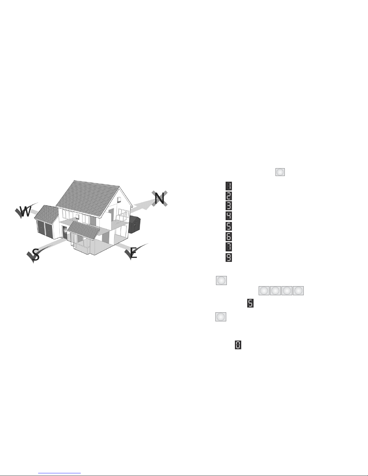
When considering the location of installing your Solarguard Bell Box, think about the area
that gets the most amount of sunlight. This page will help you consider the possibilities.
The best position to mount your Solarguard bell box is on a south-facing wall. This is
because it is the most likely position to attract the sunlight. Another location is the East and
West walls. However, it is most likely that these places are only half as effective. (Only
visible to the sun for half a day!)
Situations to avoid:
• A complete shaded wall
• Avoid shadows from guttering roof overhangs, fascia boards, neighbouring walls etc.
(Note: It is best to mount the Bell Box 1 metre below the guttering)
• Avoid placing near metallic objects, i.e. drainpipes, gutters & internal radiators.
STEP 8
Installing the Bell Box
Page 14

continued...
Page 15
SIREN
DURATION
Sets the length of
time the siren will
sound for in an
alarm condition
JAMMING
Select wether
radio jamming
detection is
switched on or
off
START
This button can
be pressed to
reset the
SolarGuard. It will
stop the siren in
the event the
alarm sounds
during installation
LEARN
Select wether
radio jamming
detection is
switched on or
off
MODE
Needs to be set
to the Bposition
FUNCTION
Setting 1 sets the
SolarGuard bell
box to give audio
indications when
the remote
control is used
(recommended).
Function 2
disables sound
output apart from
a full alarm
When you are considering installing the bell
box, please ensure that all the settings inside
the bell box are exactly to the specifications
on the picture to the right. This will ensure
that there are no complications.
This can be done by unscrewing
the two screws at the bottom of the bell box.
Otherwise, it can be checked when adding
the battery (see Bell Box installation section)
This function is allows users to call in from anywhere in the world to access the system.
Users calling in will have the ability to enter the system into Full Arming Mode or
Disarming mode, as well as monitor/listen in (via built-in microphone on control panel) or
speak (via built-in 2-way speakerphone feature). This can all be accomplished by
pressing specified keys on any keypad, while calling in from anywhere in the world.
Remote Access from Any Outside Telephone
The user must call into the system, and the system should pick up in certain amount of rings
as specified by the Remote call-in ring cycle. The caller’s procedure and options are as
follows:
1) Call the phone number that is connected to the control panel
2) Wait for the system to answer in correct amount of rings (as specified while
programming remote call-in ring cycle)
3) When you hear the confirmation tone, enter your new (or default) PIN
4) Within 10 seconds after you hear the confirmation tone, press a key for the
desired function as follows.
• Press 1 to Enter full arming mode (Confirmation = 1 beep)
• Press 0 to Enter Disarming mode (Confirmation = three beeps)
• Press # to Enter Partial Arming Mode (confirmation = two beeps)
• Press 4 to monitor/listen in (Confirmation = one long beep)
• Press 5 to Speak via 2-way speakerphone (Confirmation = one long beep)
• Press 8 to Speak via 2-way speakerphone (Confirmation = one long beep)
Continued...
This feature records the last zone that was activated during an alarm activation. When
disarming the system after any Alarm activation, the control panel will beep (one beep
per second) to remind the user that an alarm has been activated, and the MODE/MEMO
LED lights steady.
Alarm Activation Memory
•To shut off the warning beeps, push any key on the keypad.
Page 26

This function is used for call recipients to respond to an alarm notification call. Call
recipients will have the option to monitor/listen in (via built-in microphone on Control
Panel), speak (via built in 2-way speakerphone feature), have the system hang up and
dial the next programmed phone number, have the system stop dialling all programmed
phone numbers, or replay the alarm notification message. This can be accomplished by
pressing specified keys on any telephone keypad, from anywhere in the world.
Respond During an Alarm Notification Call
Upon alarm activation, the auto-dialer will call out to each of the programmed phone
numbers and play the Alarm Notification Message (as recorded by user). The call recipients
procedure and options are as follows:
1) Answer the call, then wait for the pre-recorded Alarm Notification Message to
finish,
2) Within 10 Seconds after you hear the confirmation tone, press a key for the
desired function:
• Press 4 to monitor or listen in
• Press 5 to Speak via 2-way Speakerphone
• Press 6 to have system hang up and dial the next programmed phone number
• Press 7 to replay the Alarm Notification message
• Press 8 to have system stop dialling all programmed phone numbers and disconnect call.
Continued...
When one of the sensors/transmitters in the system has a low battery, the control panel
will beep (one beep per 3 seconds) to remind the user, and the RF LINK/LOW BAT LED
will flash.
Low Battery Notification
To check the zone of the sensor/transmitter with a low battery, press the
The LED will display the zone number that the sensor operates on.
*
key.
Page 25
Where should I install the bell box?
Ideally, the bell box should be located on a
south facing wall in position where it will
receive a good level of sunlight. If this is not
possible then an east or west facing wall with
good sunlight should be acceptable.
STEP 1
Following the supplied “MAIN UNIT FIXING
HOLE TEMPLATE”, drill 3 holes using a 5mm
Masonry bit. Insert the supplied 3 x Plastic
Wall Plugs into the holes.
STEP 2
Insert the top screw and hang the SolarGuard
bell box on the wall.
STEP 3
Remove the blue cover by removing the
screws located on either side.
STEP 4
Insert the two remaining screws into the
holes on either side of the SolarGuard circuit
board.
STEP 5
Insert the supplied 6V Sealed lead acid
battery and connect battery terminals. Ensure
that red is connected to positive on the
battery, and black is connected to negative
on the battery.
NOTE:
IMPORTANT NOTICE.
PLEASE FOLLOW YOUR POWER
TOOLS SAFETY GUIDELINES.
ALWAYS USE AN RCD BREAKER
WITH MAINS POWER TOOLS.
PRO’s TIP!
To avoid false
triggering caused
by the rear tamper
switch not making
good contact with
the wall, place a
piece of lin or
plastic behind the
rear tamper switch
to create a flat
surface flush with
the bell box.
continued...
The Solarguard bell box contains some switches which are not used
with this alarm system. The only switch that is important is the MODE
switch that must be in position B to work with this system. There is
also a jack plug socket on the PCB just above the START switch that
can be used to plug in a power supply to give the battery a boost
charge. (Please note the polarity on the board)
Page 16

STEP 9
Learning the control panel code
to the Bell Box
The SG4000 Control Panel needs to learn
the security code from the Wireless bell box
before they can communicate.
STEP 1:
Remove the blue cover on the front of the
wireless bell box. This is held in place by 2
screws on the lower edge.
(note: If you are testing the system before installing,
keep the bell box at least 2-3m away from the control
panel)
STEP 2:
Install the 6V lead acid battery and ensure
that the MODE switch is in position ‘B’.
STEP 3:
Press the PANIC button on the control
panel. The control panel built in siren will
sound.
STEP 4:
After 2 seconds, press the learn button on
the bell box.
(note: The delay is very important as the panel has a 2
second delay before transmitting.)
STEP 5:
The LED on the wireless bell box will
illuminate and the bell box should emit 2
beeps to indicate that the system has
learned.
STEP 6:
The wireless Bell Box may sound once
learning is successful. If this happens, then
let the alarm sound for 10 seconds, then
disable it at the control panel. The 10 second
delay is important to ensure that the panel
will have completed its transmission.
Otherwise, it may not disarm the Bell Box. If
this happens, press the panic button again,
and wait for 15 seconds before disarming
the system.
NOTE:
It is best to unplug the telephone line
so that the control panel won’t dial
out!
NOTE:
The LED will only remain lit for 5
seconds.If the wireless Bell Box does
not bleep twice within this period,
you must repeat the steps above. You may
need to try several times to get the timing
of signals right.
Page 17
This function is used to activate the alarm during an on-site emergency or panic situation
Press the PANIC
The system will immediately activate the alarm, sound the siren and immediately begin
dialing the programmed phone numbers.
Enter Emergency/Panic Alarm
STEP 1
STEP 2
button
Using Pocket Remote:
Using the Keypad on the Control Panel:
Continued...
Press the PANIC
The system will immediately activate the alarm, sound the siren and immediately begin
dialing the programmed phone numbers.
STEP 1
STEP 2
button on the control panel
NOTE: This button can also be used to enter a 2-way speakerphone call
during an incoming phone call (Never to be used for outgoing phone calls)
Page 24

This function is used to disarm the entire system (all Zones) and all sensors/detectors.
Press the MODE
Within a few seconds you will hear three chirps as a confirmation, and a setting is
accomplished.
How to Disarm
STEP 1
STEP 2
Enter the
STEP 3
button
Using Pocket Remote:
Using the Keypad on the Control Panel:
Enter your (new or default) PIN
STEP 2
Wait until the LED displays:
STEP 2
0
key
(Command Code for this function)
Within a few seconds after the confirmation tone you will hear three beeps, & the setting is
complete.
STEP 4
Continued...
Enter the
STEP 1
S
key
2 3 41
Page 23
STEP 9 TROUBLESHOOTING
The steps described below are an alternative version to the stages previously. We have
found this cycle to be less complicated and in most circumstances more reliable on
completion. However, we have only included this as an additional help page. All the stages
are similar, but we recommend two people are present; one at the bell box, while the other
stands at the control panel.
STEP 1:
Remove the blue cover on the front of the
wireless bell box. This is held in place by 2
screws on the lower edge.
(note: If you are testing the system before installing,
keep the bell box at least 2-3m away from the control
panel)
STEP 2:
Install the 6V lead acid battery and ensure
that the MODE switch is in position ‘B’.
STEP 3:
Press the PANIC button on the control panel. The control panel built in siren will sound.
STEP 4:
After 15 seconds, Disarm using your PIN
(Default: 1234)
followed quickly by the learn
button on the bell box.
STEP 5:
The LED on the wireless bell box will
illuminate and the bell box should emit 2
bleeps to indicate that the system has
learned.
STEP 6:
The wireless Bell Box may sound once
learning is successful. If this happens, then let
the alarm sound for 10 seconds, then disable
it at the control panel. The 10 second delay is
important to ensure that the panel will have completed its transmission. Otherwise, it may
not disarm the Bell Box. If this happens, press the panic button again, and wait for 15
seconds before disarming the system.
Page 18

Page 19
Control Panel Functions
Introduction
Panic Button
Used in a distressed
situation
Internal Mic
Records what is happening
when the alarm has been
triggered. Used for the
remote call-in feature.
Telelphone Link
steady light when telephone
line is linking
LED display panel
Use this to programming
and various displays
AC Power
Steady light when the
power is normal.
Keypad
This is the input section for
the Solarguard. It is where
the arming/disarming &
programming takes place.
This function is to arm only the perimeters of the system. (Zones 2 & 3 are disabled). It is
best to use Partial Arming mode as an ‘At-Home’ security mode whenever remaining on
the premises. This allows you to roam within your alarmed premises (home, office, etc.)
without activating the PIR Motion Detectors, while the perimeters (doors, windows, etc.)
will remained armed.
Continued...
Enter Partial Arming Mode
Enter the
STEP 1
S
key
Enter the
STEP 3
Enter your (new or default) PIN
STEP 2
Wait until the LED displays:
STEP 2
#
key
(Command Code for this function)
Within a few seconds after the confirmation tone you will hear a beep, & the setting is
complete
STEP 4
NOTE: When entering Full arming & Partial Arming modes, the unit will
emit countdown beeps after the confirmation tone.
2 3 41
Page 22

Day to Day Operation
Operating your alarm system
Page 21
Operating the Alarm System manageable and easily
NOTE: If you pause while entering a programming sequence, the unit may
not accept it. If this occurs, enter the sequence again.
This function is used to arm the entire system (all zones) and all sensors/detectors. It is
best to use Full Arming Mode whenever leaving the premises.
Press the MODE
Within a few seconds you will hear one chirp as a confirmation, and a setting is
accomplished.
Enter Full Arming Mode
STEP 1
STEP 2
Operating the Wireless Alarm System is a pleasure, thanks to the Pocket Remote and the
user-friendly operating procedures. Some functions can be operated utilising the pocket
remote, keypad on the Control Panel, or from anywhere in the world via the intuitive
remote call-in feature which allows users to operate the system from any telephone. The
following operation instructions will help you to fully benefit from the many features and
functions of the Wireless Alarm System which will help you on a daily basis.
Enter the
STEP 3
button
Using Pocket Remote:
Using the Keypad on the Control Panel:
Enter your (new or default) PIN
STEP 1
Wait until the LED displays:
STEP 2
2 3 41
1
key
(Command Code for this function)
Within a few seconds after the confirmation tone you will hear a beep, & the setting is
complete
STEP 4
This function is to arm only the perimeters of the system. (Zones 2 & 3 are disabled). It is
best to use Partial Arming mode as an ‘At-Home’ security mode whenever remaining on
the premises. This allows you to roam within your alarmed premises (home, office, etc.)
without activating the PIR Motion Detectors, while the perimeters (doors, windows, etc.)
will remained armed.
Continued...
Enter Partial Arming Mode
Enter the
STEP 1
S
key
Enter the
STEP 3
Enter your (new or default) PIN
STEP 2
Wait until the LED displays:
STEP 2
#
key
(Command Code for this function)
Within a few seconds after the confirmation tone you will hear a beep, & the setting is
complete
STEP 4
NOTE: When entering Full arming & Partial Arming modes, the unit will
emit countdown beeps after the confirmation tone.
2 3 41
Page 22
Other manuals for SOLARGUARD SG4000
1
Other AEI Security & Communications Security System manuals

AEI Security & Communications
AEI Security & Communications SOLARGUARD SG4000 Operation manual

AEI Security & Communications
AEI Security & Communications SolarGuard SG1100ARM2 User manual

AEI Security & Communications
AEI Security & Communications DE40BWB User manual

AEI Security & Communications
AEI Security & Communications CTVM300AWK User manual

AEI Security & Communications
AEI Security & Communications 3400 User manual


