AEM SM40 User manual

SPECIAL NOTICE
This product is now licensed to Anodyne Electronics Manufacturing (AEM) from Northern
Airborne Technology (NAT). AEM is responsible for all matters related to this product, including
sales, support and repair services.
Please note the transition to convert product manuals and supporting documentation is an
ongoing process and is being addressed on an ‘as needed’ basis.
All references to NAT product part numbers (and associated images) are equivalent to AEM
product part numbers.
Contact info:
Anodyne Electronics Manufacturing Corp.
#15-1925 Kirschner Road
Kelowna B.C. Canada
V1Y 4N7
Email: support@aem-corp.com
Toll Free: 1-888-763-1088
Phone: 1-250-763-1088
Fax: 1-250-763-1089
www.aem-corp.com
CONFIDENTIAL AND PROPRIETARY TO ANODYNE ELECTRONICS MANUFACTURING CORP.
INSTALLATION AND OPERATION MANUAL
REV 5.00 May 15, 2012
Anodyne Electronics Manufacturing Corp.
15-1925 Kirschner Road
Kelowna, BC, Canada.
V1Y 4N7
Telephone (250) 763-1088
Facsimile (250) 763-1089
Website: www.aem-corp.com
© 2012 Anodyne Electronics Manufacturing Corp. (AEM),
All Rights Reserved
SM40
UT12
-000
Universal Tone Encoder/Decoder

UT12-000 Universal Encoder/Decoder
SM40 Installation and Operation Manual
Installation and Operation Manual Page ii
ENG-FORM: 820-0100.DOTX
CONFIDENTIAL AND PROPRIETARY TO ANODYNE ELECTRONICS MANUFACTURING CORP.
COPYRIGHT STATEMENT
© 2012 Anodyne Electronics Manufacturing Corp. (AEM), All Rights Reserved
This publication is the property of AEM and is protected by Canadian copyright laws.
No part of this document may be reproduced or transmitted in any form or by any
means including electronic, mechanical, photocopying, recording, or otherwise, without
the prior written permission of AEM.

UT12-000 Universal Encoder/Decoder
SM40 Installation and Operation Manual
Installation and Operation Manual Page iii
ENG-FORM: 820-0100.DOTX
CONFIDENTIAL AND PROPRIETARY TO ANODYNE ELECTRONICS MANUFACTURING CORP.
Prepared By:
Checked By:
Approved By:
The status of this installation and operation manual is controlled by the revision shown on the title page.
The status of each section is controlled by revision shown in the footer of each page. All revisions
affecting sections of this manual have been incorporated.
AEM MANUAL REVISIONS
Section
Revision Number
Revision Description
Date
All
Rev: 5.00
Updated template
May 15, 2012
Tony Pearson
Designer
May 15, 2012
Loen Clement
Designer
Jun 07/12
Tom Betzelt
Product Support
Manager
June 11, 2012

UT12-000 Universal Encoder/Decoder
SM40 Installation and Operation Manual
Installation and Operation Manual Page iv
ENG-FORM: 820-0100.DOTX
CONFIDENTIAL AND PROPRIETARY TO ANODYNE ELECTRONICS MANUFACTURING CORP.
Table of Contents
Section Title Page
1.0 Description
1.1 Introduction 1-1
1.2 Purpose of Equipment 1-1
1.3 Features 1-1
1.4 Specifications 1-2
1.4.1 Electrical Specifications 1-2
1.4.2 Physical Specifications 1-3
1.4.3 Environmental Specifications 1-3
2.0 Installation
2.1 Introduction 2-1
2.2 Unpacking and Inspection 2-1
2.2.1 Warranty 2-1
2.3 Installation Procedures 2-1
2.3.1 Warnings 2-1
2.3.2 Cautions 2-1
2.3.3 Cabling and Wiring 2-2
2.3.4 Post-Installation Checks 2-2
2.3.5 External Adjustments 2-2
2.4 Continued Airworthiness 2-3
2.5 Accessories Required But Not Supplied 2-3
2.6 Installation Drawings 2-3
3.0 Operation
3.1 Introduction 3-1
3.2 General 3-1
3.3 Controls and Indicators 3-1
3.3.1 MON (Monitor) Switch 3-1
3.3.2 Alphanumeric Pushbuttons 3-2
3.3.3 Function Pushbuttons 3-2
3.3.4 Mode button 3-3
3.4 Functions 3-4
3.4.1 Data Entry Mode Operation 3-4
3.4.2 Tones Mode 3-5
3.5 Reception (Decoding) 3-10
3.5.1 Receiving Regular Call 3-10
3.5.2 Receiving Group Call: 3-10
3.5.3 Receiving Alarm Call: 3-10
3.5.4 Operation when the transceiver is scanning: 3-11

UT12-000 Universal Encoder/Decoder
SM40 Installation and Operation Manual
Installation and Operation Manual Page v
ENG-FORM: 820-0100.DOTX
CONFIDENTIAL AND PROPRIETARY TO ANODYNE ELECTRONICS MANUFACTURING CORP.
Section Title Page
3.6 Transmission (Encoding) 3-12
3.6.1 Transmitting Regular Calls: 3-12
3.6.2 Transmitting UT12’s ID sequence 3-12
3.7 Tone Sequence Details 3-12
3.7.1 LAM-LA-M Radionetwork 3-13
3.7.2 AFN –Air Force Radionetwork 3-13
3.8 Configuration Mode 3-14
3.8.1 Unit Configuration 3-14
3.8.2 Configurable Information 3-14
3.8.3 Non-Configurable Information 3-15
3.8.4 LAN/AFN Network Selection 3-15

UT12-000 Universal Encoder/Decoder
SM40 Installation and Operation Manual
May 15, 2012 Rev: 5.00 Page 1-1
ENG-FORM: 800-0100.DOTX
CONFIDENTIAL AND PROPRIETARY TO ANODYNE ELECTRONICS MANUFACTURING CORP.
Section 1.0 Description
1.1 Introduction
This manual contains information on the UT12-000 Universal Tone Encoder\Decoder. Information in this
section consists of equipment, features and specifications.
UT12-000 Universal Encoder\Decoder
1.2 Purpose of Equipment
The UT12 is capable of encoding and decoding 5-tone CCIR tone sequences and encoding DTMF tones. It is
compatible with the AEM Tac/Com control head will provide broader and easier control over tones.
1.3 Features
System configuration data (such as identity codes) is programmed by use of front panel switches or by
connecting the UT12 to an IBM-compatible PC through the serial data port.
Front panel pushbutton controls are provided to allow the operator to perform the basic functions of
entering, sorting, recalling and transmitting tone sequences, as well as allowing the entry of configuration
data.
The UT12 is capable of alerting the user to various system conditions through either an externally
generated tone or by injecting a tone directly into the headphone audio line.
The UT12 may also be used as a data entry pad for the Tac/Com control head, allowing quick selection of
channels and entry of frequency data.
Based on the configuration data, control head settings, and tone inputs, the UT12 is capable of turning on
and off headphone audio from the transceiver to the head phone/audio controller.
The UT12 will operate on both the LA-M/Health Network (LAM) and Air Force Network (AFN). Operation
on each of the networks will be similar, with the exception of some differing 5-tone CCIR sequences. If
the transmit frequency falls between 147 MHz and 154 MHz the UT12 will operate on the AFN Network,
otherwise it will operate on the LAM Network.

UT12-000 Universal Encoder/Decoder
SM40 Installation and Operation Manual
May 15, 2012 Rev: 5.00 Page 1-2
ENG-FORM: 800-0100.DOTX
CONFIDENTIAL AND PROPRIETARY TO ANODYNE ELECTRONICS MANUFACTURING CORP.
1.4 Specifications
1.4.1 Electrical Specifications
Input Power
Nominal 28 Vdc @ < 1.5 A
Max. 30.3 Vdc
Min. 24.8 Vdc
Emerg. 20.0 Vdc
Input Signals
Tone Audio: 300 mV into 1 kΩ
Head phone Audio: 10 W max. Into 600 Ω
Mic audio: 0 -1 Vrms
PTT: Active low
Output Signals
Head phone Level, On: >1 dB from headphone audio input into 150 Ω
Headphone Level, Muted: <-55 dB from headphone audio input into 150 Ω
Microphone Audio,
Tone Level: 0 –1 Vrms into 150 Ω(adjustable.)
Tone frequency error: < 0.5 %
Tone types: CCIR, DTMF, Single
PTT: Active low, 200 mA max.
Alert key: Active low, 30 mA max.
Miscellaneous Signals
Tx Data Out: RS232C, 2400 baud
Rx Data In: RS232C, 2400 baud
Lighting +28 Vdc < 50 mAdc

UT12-000 Universal Encoder/Decoder
SM40 Installation and Operation Manual
May 15, 2012 Rev: 5.00 Page 1-3
ENG-FORM: 800-0100.DOTX
CONFIDENTIAL AND PROPRIETARY TO ANODYNE ELECTRONICS MANUFACTURING CORP.
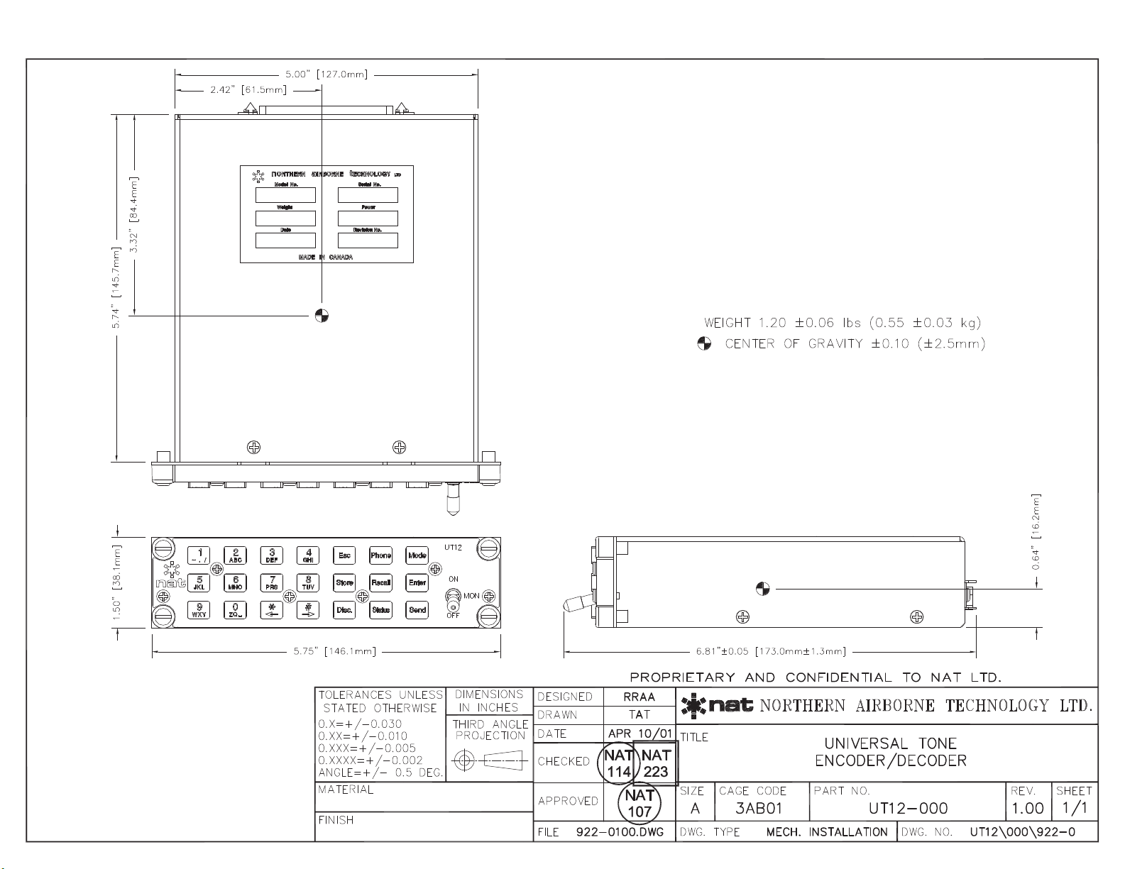
1.4.2 Physical Specifications
Height 1.50" (38.10 mm)
Depth 6.2" (157.48 mm)
5.75” (146.05mm) behind panel
Width 5.75" (146.05 mm)
5.00” (127.00 mm) behind panel
Weight 1.02 lbs (544g)
Mounting Dzus rail
Material/Finish Aluminum/Conversion Coating
Connector Filtered 37 pin male Dmin
Lighting Acceptable for operation with NVG Gen III goggles
1.4.3 Environmental Specifications
Temperature:
Operating -30qC. to +60qC
Survival -55qC. to + 85qC
Altitude 25,000 feet
Humidity 95%
Shock 12 g (all axes)
Environmental categories
RTCA/DO-160C Env. Cat. B4-BA(MN)XXXXXXABBZAUBXXX
End of Section 1.0

UT12-000 Universal Encoder/Decoder
SM40 Installation and Operation Manual
May 15, 2012 Rev: 5.00 Page 2-1
ENG-FORM: 805-0100.DOTX
CONFIDENTIAL AND PROPRIETARY TO ANODYNE ELECTRONICS MANUFACTURING CORP.
Section 2.0 Installation
2.1 Introduction
Information in this section consists of unpacking and inspection procedures, installation procedures, post-
installation checks, and installation drawings.
2.2 Unpacking and Inspection
Unpack the equipment carefully. Inspect the unit visually for damage due to shipping and report all such
claims immediately to the carrier involved. Note that each unit should have the following:
- UT12 Universal Encoder/Decoder
- Product Information Card
- Release certification
Verify that all items are present before proceeding and report any shortage immediately to your supplier.
2.2.1 Warranty
All Anodyne Electronics Manufacturing Corp. (AEM) products are warranted for 2 years. See the website
www.aem-corp.com/warranty for complete details.
2.3 Installation Procedures
2.3.1 Warnings
Do not bundle any lines from this unit with transmitter coax lines. Do not bundle any audio or DC power
lines from this unit with 400 Hz synchro wiring or AC power lines. Do not position this unit or wiring from
this unit next to any device with a strong alternating magnetic field such as an inverter, or significant
interference will result.
2.3.2 Cautions
In all installations, use shielded cable exactly as shown and ground as indicated. Significant problems
may result if these guidelines are not followed.

UT12-000 Universal Encoder/Decoder
SM40 Installation and Operation Manual
May 15, 2012 Rev: 5.00 Page 2-2
ENG-FORM: 805-0100.DOTX
CONFIDENTIAL AND PROPRIETARY TO ANODYNE ELECTRONICS MANUFACTURING CORP.
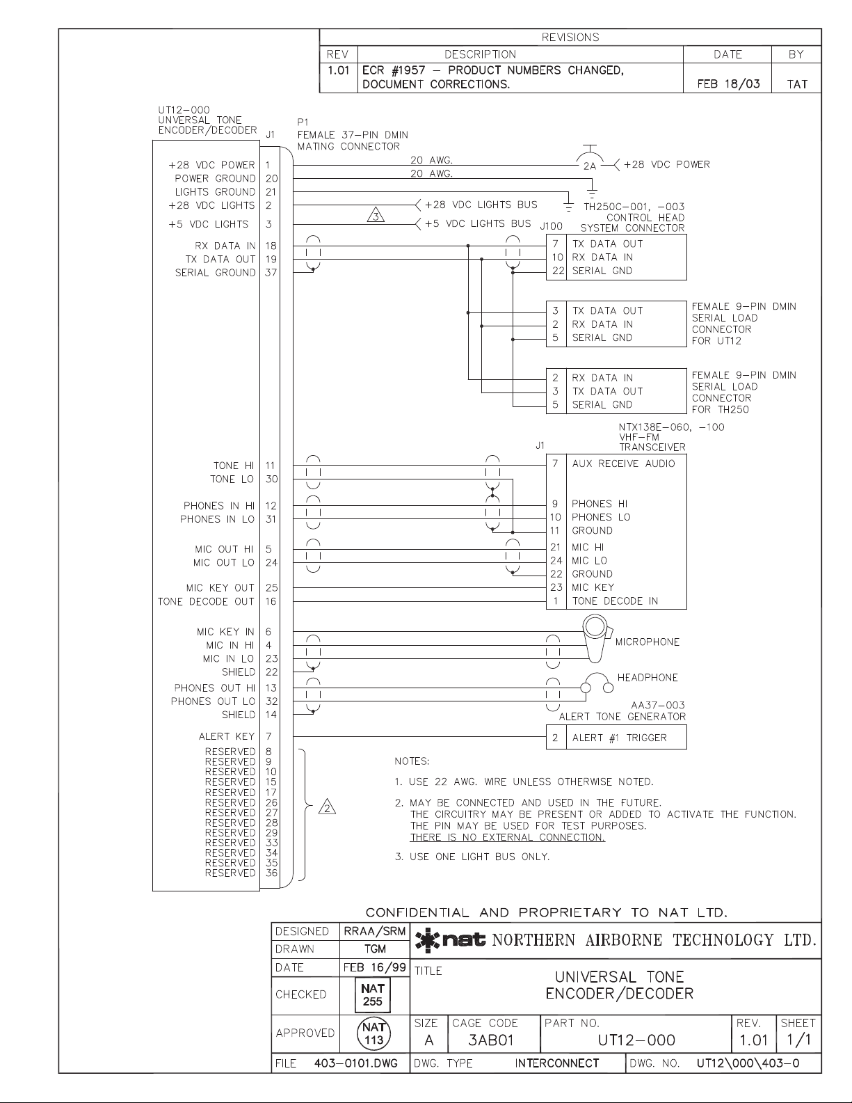
2.3.3 Cabling and Wiring
All unshielded wire should be MIL-W-22759 or equivalent. For shielded wire applications, use Tefzel MIL-
C-27500 shielded wire with solder sleeves (for shield terminations) to make the most compact and easily
terminated interconnect. Follow the wiring diagrams in Section 2.6 as required.
Allow 3 inches from the end of the wire to the shield termination to allow the hood to be easily installed.
Note that the hood is a ‘clamshell’ hood, and is installed after the wiring is complete.
All wiring should be at least 22 AWG, except power and ground lines, which should be at least 20 AWG.
Ensure that all ground connections are clean and well secured.
2.3.4 Post-Installation Checks
If any preset requires adjustment, be sure this is carried out before the aircraft leaves, and that the unit
and its mating connector are secured before departure. Make all required log book entries, electrical
load, weight and balance amendments and other paperwork as required by your local regulatory agency.
2.3.4.1 Voltage/resistance checks
Do not attach the UT12 until the following conditions are met.
Check the following:
a) P101 pins <1> and <2> for +28 Vdc relative to ground.
b) P101 pins <20> and <21> for continuity to ground (below 0.5Ω)
2.3.4.2 Power On checks
Install the UT12 and power up the ship’s systems. Turn on the Universal Tone Encoder/Decoder. Verify
normal operation of all functions. Refer to Section 3 for specific operation details.
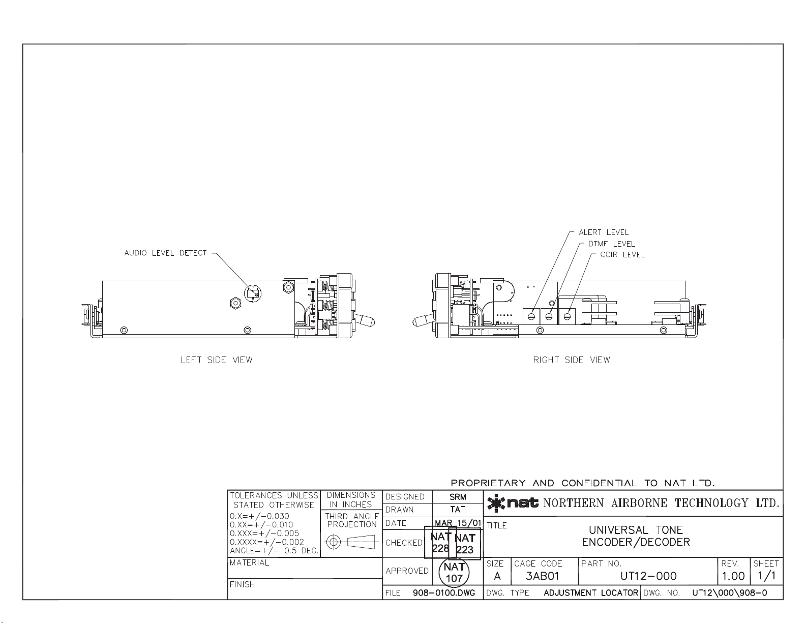
2.3.5 External Adjustments
The unit is shipped from the factory with all external adjustments set to the normal test levels. Once
installed in the aircraft, it may be desirable to change some of these settings to best suit the local
operating environment. The external adjustments are accessible through the right hand side of the unit
and are as follows:
CCIR LVL Adjusts the signal level of the CCIR tone sent to the transceiver.
ALRT LVL Adjusts the signal level of the tone alert signal sent to the headset.
DTMF LVL Adjusts the threshold level setting for determining a valid tone signal received
transceiver. (Located on left side of unit).
Upon satisfactory completion of all performance checks, make the required log entries and
complete the necessary Regulatory Agency paperwork before releasing the aircraft for service.

UT12-000 Universal Encoder/Decoder
SM40 Installation and Operation Manual
May 15, 2012 Rev: 5.00 Page 2-3
ENG-FORM: 805-0100.DOTX
CONFIDENTIAL AND PROPRIETARY TO ANODYNE ELECTRONICS MANUFACTURING CORP.
2.4 Continued Airworthiness
Maintenance of the UT12-000 is ‘on condition’ only. Periodic maintenance of this product is not required.
2.5 Accessories Required But Not Supplied
Installation kit p/n D37SV-IKC is required to complete the installation. Each kit consists of the following:
Quantity Description AEM Part #
1 D-min 37 Socket Housing 20-21-037
37 MS Crimp Socket 20-26-901
1 37 Pin JVL Hood/Locklever 20-29-370
2.6 Installation Drawings
DRAWING
REV.
DESCRIPTION
TYPE
UT12\000\403-0
1.01
Universal Tone Encoder/Decoder
Interconnect
UT12
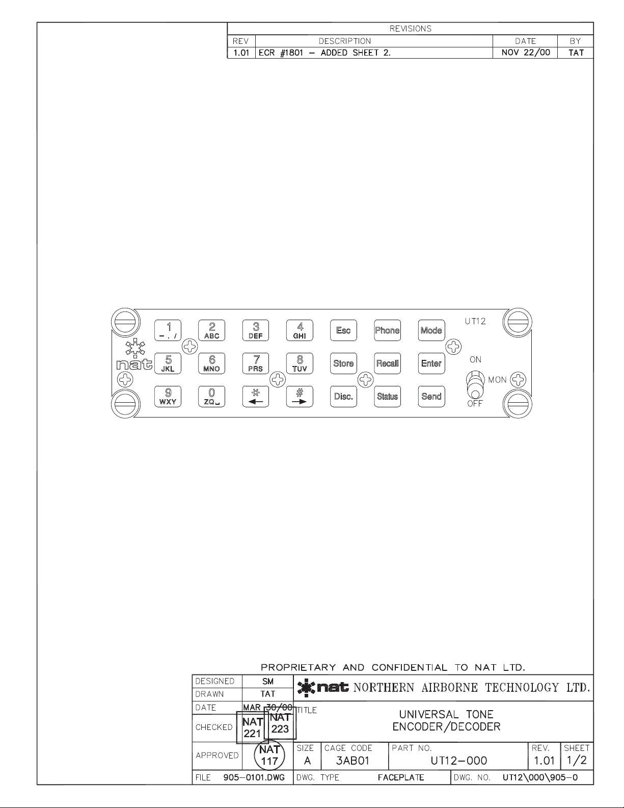
\000\905-0 1.01
Universal Tone Encoder/Decoder
Faceplate
UT12
\000\908-0 1.00
Universal Tone Encoder/Decoder
Adjustment Locator
UT12
\000\922-0 1.00
Universal Tone Encoder/Decoder
Mechanical
Section 2.0 ends following above documents
UT12-000 Universal Encoder/Decoder
SM40 Installation and Operation Manual
May 15, 2012 Rev: 5.00 Page 3-1
ENG-FORM: 806-0100.DOTX
CONFIDENTIAL AND PROPRIETARY TO ANODYNE ELECTRONICS MANUFACTURING CORP.
Section 3.0 Operation
3.1 Introduction
Information in this section consists of the functional and operational procedures for the UT12-000
Universal Tone Encoder/Decoder.
3.2 General
The UT12 is capable of encoding and decoding 5-tone CCIR tone sequences and encoding DTMF tones.
It is compatible with the NAT Tac/Com system, and when used in conjunction with a TH-series Tac/Com
control head and NTX series transceiver it provides broader and easier control over radio communication.
3.3 Controls and Indicators
3.3.1 MON (Monitor) Switch:
The monitor switch is a two position locking toggle switch that can select between OFF and ON.
When in the Monitor OFF position, transceiver audio from the current channel (or home channel when
scanning) is only heard if the correct tone ID sequence is decoded.
When in Monitor ON position, transceiver audio from the current channel (or home channel when
scanning) is always heard.
The following functions are unaffected by the position of the MON Switch:
Transceiver audio is always heard from the priority scan channels, guard receive channels, and list scan
channels with correct tone sequences; Transceiver audio from list scan channels that do not have correct
tone ID sequence is not heard.
UT12-000 Universal Encoder/Decoder
SM40 Installation and Operation Manual
May 15, 2012 Rev: 5.00 Page 3-2
ENG-FORM: 806-0100.DOTX
CONFIDENTIAL AND PROPRIETARY TO ANODYNE ELECTRONICS MANUFACTURING CORP.
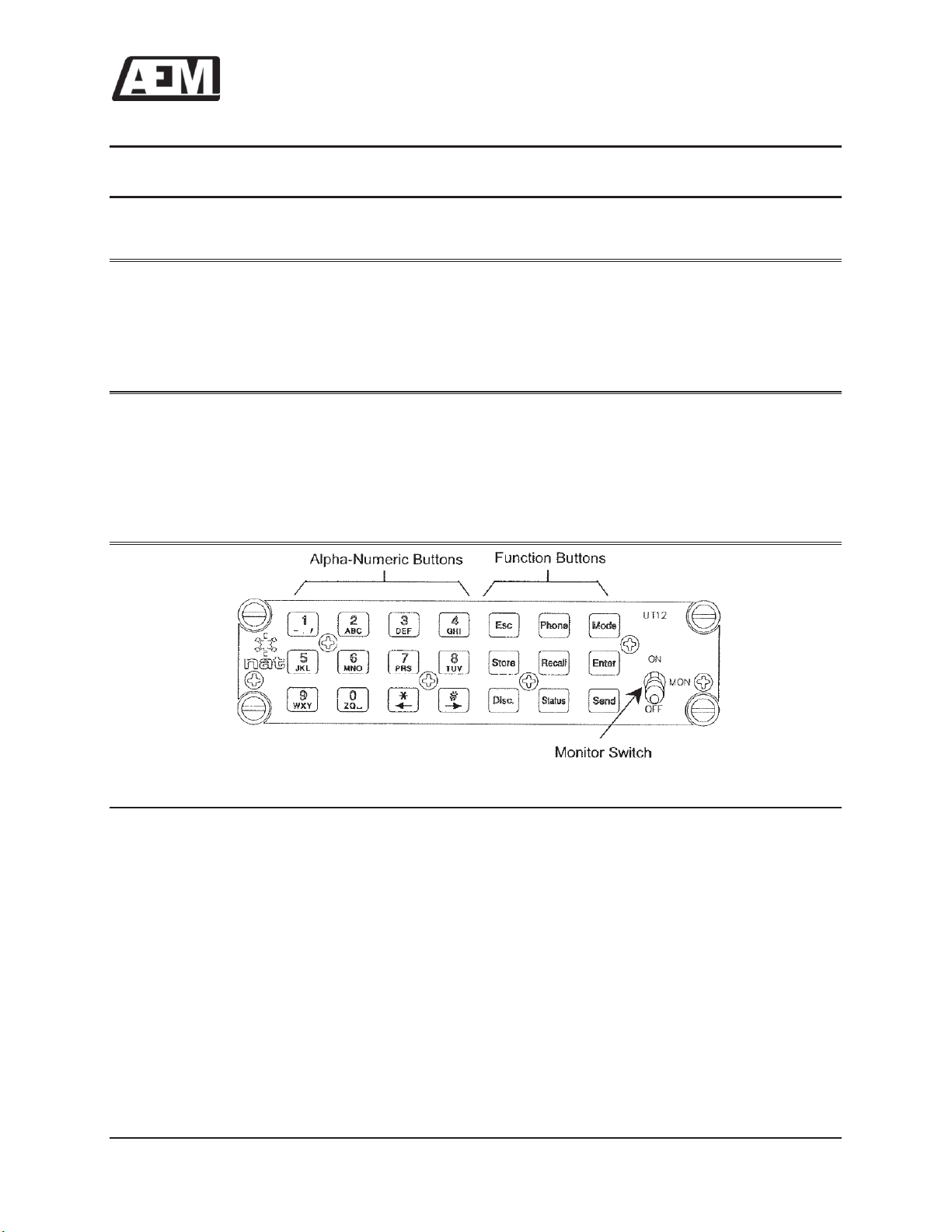
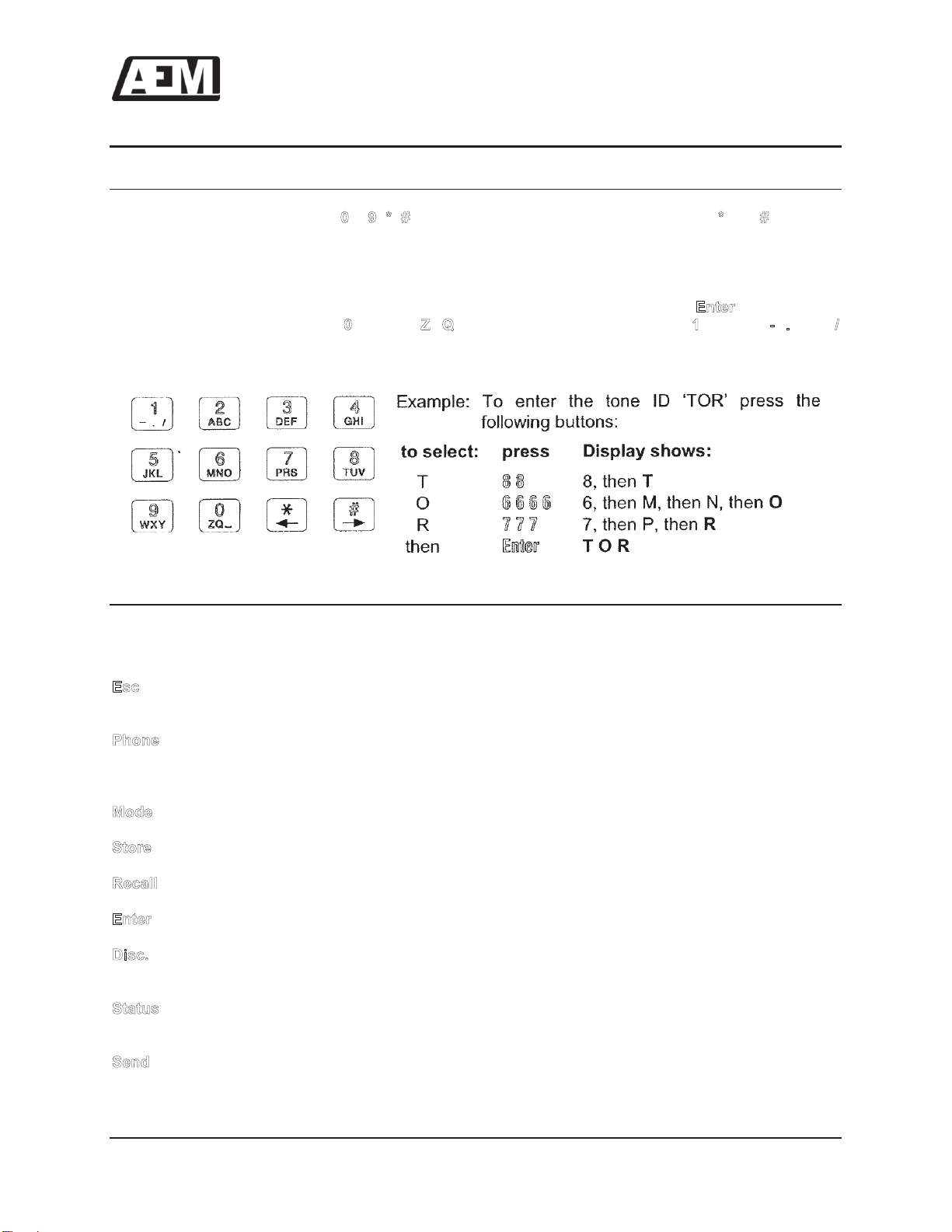
3.3.2 Alphanumeric Pushbuttons
The Alphanumeric Pushbuttons ( –, , ) are used for entry of tones and data. The and keys also
function as left (←) and right (→) arrows to be used for scrolling.
To enter an alphanumeric character for Ids or names, repeatedly press a number button until the desired
character is displayed, then press a different numbered button or the right arrow button to advance to the
next space. Press the left arrow button to change a previous character. Press the button to save
the tone ID name. The button has the ,, and _ (space) characters, and has the ,, and
characters.
3.3.3 Function Pushbuttons
The basic functions of the operator controls are listed below. Detailed operation will be discussed in
sections 3.4 through 3.8.
:
Used to cancel operation and reset control head display. Also used to turn off the external
alert key if on. May display a brief software message when no other activity is in progress.
:
Used to transmit CCIR phone activation sequence. Automatically selects DTMF as mode
type after sequence is sent.
After disconnect or 20 seconds af
ter loss of carrier the mode
type returns to CCIR.
:
Used to change the system tone type, enter DATA mode, and turn the scrambler on or off.
:
Used to store tone information in memory.
:
Used to recall tone information from memory.
:
Used to complete operation or to check current buffer status.
:
Used to disconnect UT12 from CCIR network, transmit call breakdown sequence, and turn off
headphone audio.
:
Used to send status information to base station. Also serves as a function key for entry into
configuration mode, and entry into serial load mode.
:
Used to transmit the tone(s) in the selected transmit buffer.

UT12-000 Universal Encoder/Decoder
SM40 Installation and Operation Manual
May 15, 2012 Rev: 5.00 Page 3-3
ENG-FORM: 806-0100.DOTX
CONFIDENTIAL AND PROPRIETARY TO ANODYNE ELECTRONICS MANUFACTURING CORP.
3.3.4 Button
The button is used to select between DATA Mode, one of three tone types, or a Scrambler on/off
Mode.
Each time the button is pressed, it moves one step through the following sequence:
DATA; Tones (CCIR, DTMF, SINGLE); and Scrambler on/off.
The UT12 is always actively decoding CCIR tone sequences.
3.3.4.1 DATA Mode
When Data Mode is selected, the UT12 acts as a data entry pad for the TH-series Tac/Com control head
to which it is connected. See section 3.4.1.
3.3.4.2 Selecting Tone Types
The UT12 is capable of generating three types of tones: CCIR, DTMF and SINGLE. The CCIR tone
mode is the default.
To change the current tone type, press the button until the desired tone type is displayed.
To change the current mode to DATA mode, press once.
CCIR and DTMF tones are industry standard tone frequencies. Single tone frequencies for the UT12
match those of the CCIR tones, but have minimum period of 2 seconds, or as long as the button is
held down. The tone frequency is displayed in SINGLE tone mode.
There are five symbols used on the control head display to denote tone types.
CCIR tones are represented by Cor CCIR
DTMF tones are represented by Dor DTMF
SINGLE tones are represented by SINGLE
3.3.4.3 Scrambler Activation/Deactivation
The UT12 can activate and deactivate the scrambler in the transceiver via serial communications with the
control head, and activate the scrambler located at the base station. To activate the scrambler, the user
must not be involved in any other operation. Press to cancel any operations in progress.
Press the button until the current scrambler status SCRAMBLER ON[OFF] is displayed on the
control head. Then press , and the message TURN OFF[ON]? will be displayed. To change the
state of the scrambler, press again, or press to leave the scrambler in the current state. When
turning on the scrambler, the control head will briefly display SCRAM ON 81097 and will transmit the
CCIR sequence 81097. When turning off the scrambler the control head will display SCRAM OFF,butno
code will be sent.
UT12-000 Universal Encoder/Decoder
SM40 Installation and Operation Manual
May 15, 2012 Rev: 5.00 Page 3-4
ENG-FORM: 806-0100.DOTX
CONFIDENTIAL AND PROPRIETARY TO ANODYNE ELECTRONICS MANUFACTURING CORP.
3.4 Functions
3.4.1 Data Entry Mode Operation
In this mode, the UT12 operates as a keyboard for the control head and allows entering of frequency
data, and channel selection.
Press the UT12-000 button once. The control head displays MODE=DATA.
3.4.1.1 Selecting a Channel on the Control Head
1) Ensure the control head Edit switch is in the OFF position.
2) Press the Keypad Number buttons of the channel you want to select. Use the same method of
channel numbering as is displayed on the control head. (The display will be unaffected at this
point.)
3) Press the button. The new channel information will then be displayed on the control head.
4) To exit without making changes, press the button instead of the button.
Example: To select channel 123, press: .
To select channel 001, press: or or and .
After pressing , the UT12 returns to CCIR mode.
Note: Only the last three channel numbers pressed before the button is pressed will be used for
channel selection. If an invalid channel number is entered, no channel change will occur and the control
head will display the message CHANNEL ERROR.
3.4.1.2 Editing Channel Information on a Control Head
When the control head is in Channel Edit Mode, the UT12-000 may be used to enter receive and transmit
frequencies and channel ID’s.
To edit a frequency:
1) Put the control head EDIT switch in the CH (Channel) position. The first editable digit in the
control head display will be flashing. The message CANNOT EDIT will be displayed if the
selected channel is ‘locked out.’
2) Put the Control Head DISPLAY switch in the TX or RX position.
3) Enter the new transmit or receive frequency on the UT12.
4) Use the keypad Number buttons (or the control head CHAN/SELECT +/-switch) to enter the
frequency digits. Use the (←) button to edit the previous digit, and the (→) button to edit the next
digit. (The decimal point and the receive/transmit/simplex flag will be skipped during editing.)
5) When the transmit tone character is flashing, it may be changed if necessary using the control
head CHAN/SELECT +/-switch. Tones cannot be edited from the UT12.
6) Put the control head DISPLAY switch to the ID position.
7) Enter the Channel ID using the alphanumeric pushbuttons. Note that only the →button can be
used to move the editable character.
8) When editing is complete, put the Control Head EDIT switch in the OFF position.
This manual suits for next models
1
Table of contents
Popular Media Converter manuals by other brands


Transition
Transition M/GE-T Series user guide

IST
IST I2000M Operation manual

artisan
artisan VMIVME-3111 instruction manual

Rockwell Automation
Rockwell Automation AEC Installation and setup manual

Yukon
Yukon HLS80E Assembly, testing, operation, servicing & storage instruction

HEIDENHAIN
HEIDENHAIN ERA 4202 Mounting instructions


