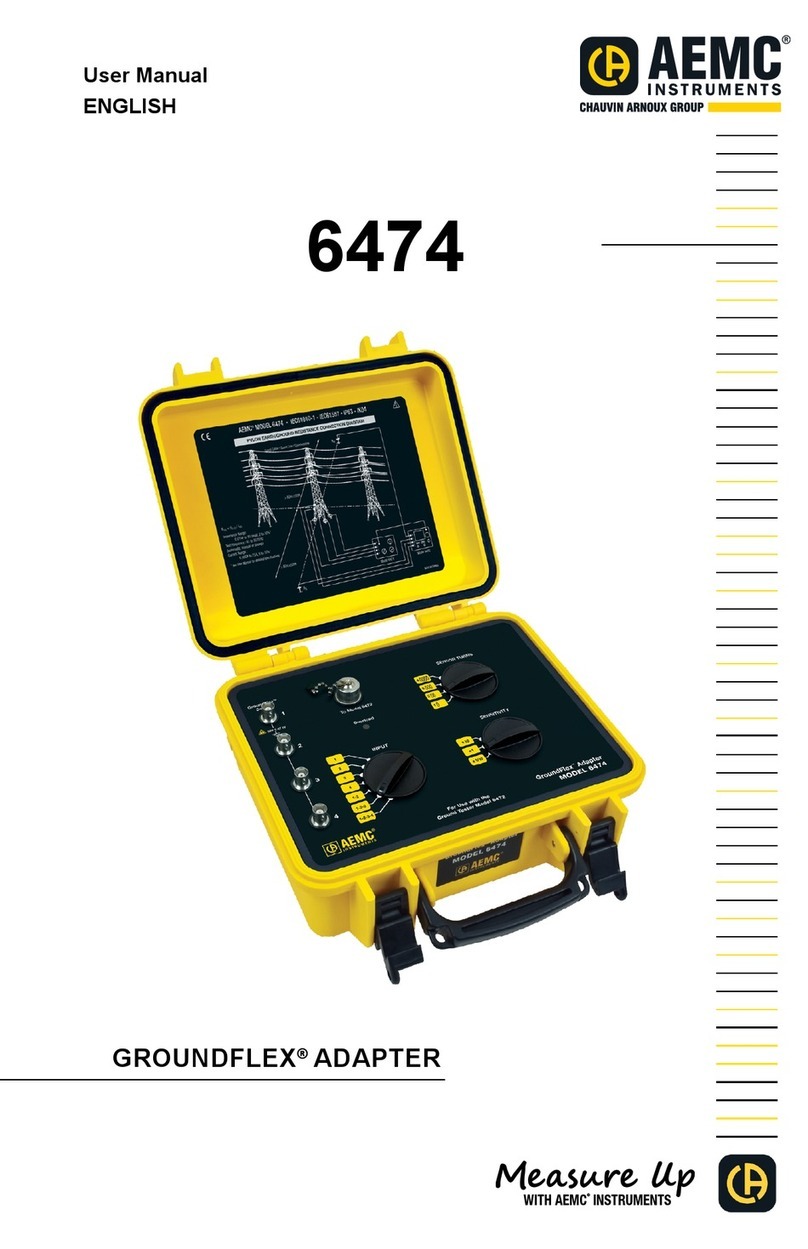
AEMC instruments GROUNDFLEX 6474 User manual

GroundFlex®Adapter
Model 6474
User Manual
ENGLISH
GROUNDFLEX®ADAPTER
WITH AEMC
®
INSTRUMENTS

Copyright©Chauvin Arnoux®, Inc. d.b.a. AEMC®Instruments. All rights reserved.
No part of this documentation may be reproduced in any form or by any means (including electronic
storage and retrieval or translation into any other language) without prior agreement and written consent
from Chauvin Arnoux®, Inc., as governed by United States and International copyright laws.
Chauvin Arnoux®, Inc. d.b.a. AEMC®Instruments
15 Faraday Drive • Dover, NH 03820 USA
Tel: (800) 945-2362 or (603) 749-6434 • Fax: (603) 742-2346
This documentation is provided as is, without warranty of any kind, express, implied, or otherwise.
Chauvin Arnoux®, Inc. has made every reasonable eort to ensure that this documentation is accurate;
but does not warrant the accuracy or completeness of the text, graphics, or other information contained
in this documentation. Chauvin Arnoux®, Inc. shall not be liable for any damages, special, indirect,
incidental, or inconsequential; including (but not limited to) physical, emotional or monetary damages
due to lost revenues or lost prots that may result from the use of this documentation, whether or not the
user of the documentation has been advised of the possibility of such damages.

Chauvin Arnoux®, Inc.
d.b.a AEMC®Instruments
www.aemc.com
Statement of Compliance
Chauvin Arnoux®, Inc. d.b.a. AEMC® Instruments
certies that this instrument has been calibrated
using standards and instruments traceable to
international standards.
We guarantee that at the time of shipping your
instrument has met the instrument’s published
specications.
An NIST traceable certicate may be requested
at the time of purchase, or obtained by returning
the instrument to our repair and calibration
facility, for a nominal charge.
The recommended calibration interval for this
instrument is 12 months and begins on the date of
receipt by the customer. For recalibration, please
use our calibration services. Refer to our repair and
calibration section at www.aemc.com/calibration.
Serial #:
Catalog #: 2136.03
Model #: 6474
Please ll in the appropriate date as indicated:
Date Received:
Date Calibration Due:

TABLE OF CONTENTS
1. INTRODUCTION.................................................................. 5
1.1 PRECAUTIONS FOR USE ........................................................ 6
1.2 RECEIVING YOUR SHIPMENT................................................ 6
1.3 ORDERING INFORMATION..................................................... 7
1.3.1 Accessories ........................................................................ 7
1.3.2 Replacement Parts............................................................. 7
2. GROUNDFLEX®ADAPTER ...............................................8
2.1 CONTROL FEATURES.............................................................. 8
2.2 GROUNDFLEX®SENSOR........................................................ 9
2.2.1 Calibration of GroundFlex®Sensors................................. 10
2.3 MEASUREMENTS IN AUTO MODE ...................................... 12
2.3.1 Preparation of the GroundFlex®Adapter .......................... 12
2.3.2 Making a Measurement (Resistance of Legs).................. 14
2.3.3 Other Measurements ....................................................... 16
2.4 MANUAL MODE AND SWEEP MODE................................... 16
2.5 TOWER TESTING MEASUREMENT..................................... 18
2.5.1 Choosing the positions for the H, S electrodes: ............... 18
2.6 GLOSSARY .............................................................................. 25
3. SPECIFICATIONS ............................................................. 26
3.1 ELECTRICAL............................................................................ 26
3.2 MECHANICAL.......................................................................... 28
3.3 ENVIRONMENTAL .................................................................. 28
3.4 SAFETY .................................................................................... 28
4. MAINTENANCE ................................................................29
4.1 CLEANING................................................................................ 29
4.2 REPAIR AND CALIBRATION ................................................. 29
4.3 TECHNICAL AND SALES ASSISTANCE .............................. 30
4.4 LIMITED WARRANTY ............................................................. 30
4.4.1 Warranty Repairs ............................................................. 31

1. INTRODUCTION
Thank you for purchasing an AEMC®Instruments GroundFlex®Adapter
Model 6474.
For the best results from your instrument and for your safety, you must
read the enclosed operating instructions carefully and comply with the
precautions for use. Only qualied and trained operators should use this
product.
Symbols & Denitions
Signies that the instrument is protected by double or reinforced insulation
CAUTION - Risk of Danger! Indicates a WARNING. Whenever this symbol
is present, the operator must refer to the user manual before operation
Indicates a risk of electric shock. The voltage at the parts marked with this
symbol may be dangerous
Indicates Important information to acknowledge
This product complies with the Low Voltage & Electromagnetic Compatibility
European directives
In the European Union, this product is subject to a separate collection
system for recycling electrical and electronic components in accordance with
directive WEEE 2012/19/EU
Ground/Earth
Denition of Measurement Categories (CAT)
CAT IV: Corresponds to measurements performed at the primary electrical
supply (< 1000 V).
Example: primary overcurrent protection devices, ripple control units,
and meters.
CAT III: Corresponds to measurements performed in the building installation
at the distribution level.
Example: hardwired equipment in xed installation and circuit
breakers.
CAT II: Corresponds to measurements performed on circuits directly
connected to the electrical distribution system.
Example: measurements on household appliances and portable tools.

6GroundFlex®Adapter Model 6474 - User Manual
1.1 PRECAUTIONS FOR USE
These safety warnings are provided to ensure the safety of personnel. Please
read and comply with these precautions:
■This instrument is protected from accidental voltages of not more than 50 V with
respect to earth in measurement CAT IV. The guaranteed level of protection
of this equipment may be compromised if used in a manner not specied by
the manufacturer.
■Safety is the responsibility of the operator.
■All metal objects or wires connected to the electrical system should be
assumed to be lethal until tested. Grounding systems are no exception.
■Never exceed the maximum rated voltage and current, and the
measurement category.
■Never exceed the protection limits, and always comply with the conditions
and place of use, indicated in the specications.
■Do not use the instrument or its accessories if they appear damaged.
■Use accessories that have overvoltage category and service voltages
greater than or equal to those of the instrument (CAT IV 50 V). Use only
accessories that comply with safety standards (IEC 61010-2-031 & 32).
■Wear the appropriate protective gear (insulating boots and gloves).
■Check that no terminal is connected and the switch is set to OFF before
opening the device.
■Use only the charging unit supplied with the instrument to recharge the
battery.
■Troubleshooting and metrological verication procedures must only be
performed by qualied, approved personnel, or the factory.
NOTE: The potentials on the various rods used for an earth
measurement may be dierent if a nearby electrical installation is
defective or certain weather conditions prevail (thunderstorms).
It is up to the operator to decide whether to continue or postpone
measurements in these situations.
1.2 RECEIVING YOUR SHIPMENT
Upon receiving your shipment, make sure that the contents are consistent with the
packing list. Notify your distributor of any missing items. If the equipment appears
to be damaged, le a claim immediately with the carrier and notify your distributor
at once, giving a detailed description of any damage. Save the damaged packing
container to substantiate your claim.

GroundFlex®Adapter Model 6474 - User Manual 7
1.3 ORDERING INFORMATION
NOTE: The GroundFlex®Adapter Model 6474 only operates in
combination with the Ground Tester Model 6472 Kit - 500 ft.
GroundFlex® Field Kit (Model 6472 and 6474) ............................. Cat. #2136.03
Includes: (Ground Tester Model 6472 Kit-500 ft (Cat #2135.54)); Model 6472,
(1) carrying bag, (2) 500 ft color-coded leads on spools (red/blue),
(2) 100 ft color-coded leads (hand tied, green/black), (1) 30 ft lead (green),
(2) 5 ft color-coded leads (red/blue), 100/240 V power adapter with US power
cord, optical USB cable, (4) T-shaped auxiliary ground electrodes, set of
(5) spaded lugs, (1) 100 ft tape measure, rechargeable NiMH battery pack, USB
stick with DataView®software, ground tester workbook and user manual.
GroundFlex® Adapter Model 6474, (4) GroundFlex®sensors (5 m), (12) color-
coded rings, connection lead, (2) extension leads on H reel (black/green) with
color-coded alligator clips, (1) extra green and black alligator clips,
(2) BNC extension leads, calibration loop, (3) C-clamps, set of (2) reel caddy,
(1) inverter 12 VDC to 120 VAC watt (vehicle use), carrying case with wheels and
handle for meters and user manual.
1.3.1 Accessories
Bag #6 - Carrying Bag for Ground Kits............................................ Cat. #2119.82
Tape Measure - AEMC®Instruments (100 ft)................................... Cat. #2130.60
Set of two, 14.5 in T-shaped Auxiliary Ground Electrodes .............. Cat. #2135.39
Optical USB Cable ........................................................................... Cat. #2135.41
1.3.2 Replacement Parts
Connection Lead for Model 6472/6474............................................ Cat. #2135.75
One BNC (15 m/50 ft) Extension Lead ............................................ Cat. #2135.76
Set of 12, GroundFlex®Rings (red, yellow, brown, orange)............. Cat. #2135.77
Green Extension Lead ..................................................................... Cat. #2135.78
Black Extension Lead ...................................................................... Cat. #2135.79
Set of 3, C-clamps ...........................................................................Cat. #2135.80
Calibration Loop............................................................................... Cat. #2135.82
Carrying Case .................................................................................. Cat. #2135.83
One GroundFlex®(5 m / 16 ft) Sensor
w/ (16 m / 52 ft) black cable.............................................................. Cat. #2135.92
Safety Alligator Clip (black)..............................................................Cat. #5000.99
Safety Alligator Clip (green) ............................................................. Cat. #5100.06
GroundFlex®Sensor (10 m / 32 ft) ................................................... Cat. #2135.87
Order Accessories and Replacement Parts Directly Online
Check our Storefront at www.aemc.com/store for availability

8GroundFlex®Adapter Model 6474 - User Manual
2. GROUNDFLEX®ADAPTER
2.1 CONTROL FEATURES
50V CAT IV
1-2-3-4
1-2-3
1-2
1
2
3
4
For Use with the
Ground Tester Model 6472
GroundFlex
®
Sensor
SENSOR TURNS
SENSITIVITY
To Model 6472
Overload
INPUT
1
2
3
4
GroundFlex®Adapter
MODEL 6474
2
4
1
6
5
3
1. Inputs 1 through 4 for GroundFlex®sensors
2. Connector for connection lead to the Ground Tester Model 6472
3. OVERLOAD indicator
4. SENSOR TURNS selector: 1, 2, 3 or 4
5. SENSITIVITY selector: x10, x1 or x1/10
6. INPUT SELECTION: 1, 2, 3, 4, 1-2, 1-3 or 1-4

GroundFlex®Adapter Model 6474 - User Manual 9
2.2 GROUNDFLEX®SENSOR
The GroundFlex®sensors are placed around a conductor (tower leg or pole) and
closed using a screw connector, which is part of the sensor. This closed loop
is then used to make a contact-free measurement of the current owing in the
conductor (leg) it is wrapped around.
These sensors are current measurement clamps but are able to enclose objects
that are much larger.
GroundFlex®sensors are available in lengths of up to approx 24 ft (8 m) and can
be placed around objects (such as tower legs) up to in approx 8 ft diameter (2.7 m).
50V CAT IV
1-2-3-4
1-2-3
1-2
GroundFlex®
Sensor
To Model 6472
Overload
INPUT
1
2
3
4

10 GroundFlex®Adapter Model 6474 - User Manual
2.2.1 Calibration of GroundFlex®Sensors
Calibration is necessary for a new sensor, one that is no longer identied when a
sensor has been replaced, or more than 2 lengths of extension cable is used. The
calibration coecients are then stored in the Model 6474.
WARNING: Do not move or touch the GroundFlex®sensor or the
calibration loop during the calibration. This could cause errors.
Start by identifying each sensor using the identication rings that are supplied
with the Model 6474: (1) Brown, (2) Red, (3) Orange, (4) Yellow
■Connect the calibration loop between terminals H and E of the Model 6472.
■Connect the Model 6472 and 6474 together using the connection cable.
■Connect the GroundFlex®sensor with the Brown ring to Input 1 of the Model
6474, the one with the Red ring to Input 2, the one with the Orange ring to
Input 3, and the one with the Yellow ring to Input 4.
■Coil the GroundFlex®sensor four times around in the calibration loop and
close it using its screw connector. Place the connector as far as possible from
the calibration device.
6472 6474

GroundFlex®Adapter Model 6474 - User Manual 11
1. Set the switch of the 6472 to SET-UP.
2. Set the SENSOR TURNS switch to 4.
3. Set the SENSITIVITY switch to x1.
4. Set the INPUT SELECTION switch to 1.
1-2-3-4
1-2-3
1-2
1
2
3
4
SENSOR TURNS
SENSITIVITY INPUT
5. Press the Hz/OPTIONS button 5 times.
The device starts by comparing the current IInt injected by the device into the
calibration loop to the current IA measured by the GroundFlex®sensor. If they are
dierent, the CAL symbol blinks to recommend a calibration.
NOTE: To avoid measurement errors, do not touch the GroundFlex®
sensor or the calibration loop during the calibration.
x 5
4
H
E
S
x
11
AUTO
mA
m A

12 GroundFlex®Adapter Model 6474 - User Manual
6. To start the calibration, press 2nd + START.
7. The device calculates and stores a calibration coecient for the GroundFlex®
sensor connected to channel 1.
4
H
E
S
x
11
AUTO
mA
m A
This operation must be repeated for channels 2, 3 and 4; the INPUT
SELECTION switch must be set to the corresponding position each time.
The calibration values are now stored into memory.
After calibration, the GroundFlex®sensors must always be connected to their
respective channels.
NOTE: Always connect the same sensor to the same input.
2.3 MEASUREMENTS IN AUTO MODE
2.3.1 Preparation of the GroundFlex®Adapter
The GroundFlex®Adapter Model 6474 is designed to be used only with the
Model 6472 device. The two instruments must be connected using the special
connection cable supplied. The Model 6474 has no ON/OFF button, and is
powered only by the Model 6472, via this connection cable.
The Model 6474 is intended primarily to measure the current that ows through
a high-voltage tower to the ground. You can wrap up to 4 legs of the towers each
with a GroundFlex® sensor and measure the current owing to earth through
each of the legs or through several legs.
1. Set the rotary function switch to GroundFlex®on the Model 6472.
2. When you connect the GroundFlex®Adapter Model 6474 to the 6472, a self-
test will begin. During this test, the OVERLOAD check light on the 6474 is lit.
3. Connect the required number of sensors to channels 1, 2, 3, and/or 4.

GroundFlex®Adapter Model 6474 - User Manual 13
NOTE:
The sensors have arrows to indicate a direction.
Always connect the same sensor to the same input.
All sensors should face the same direction (clockwise or counter-
clockwise around the tower legs)
All sensors should have the same number of wraps
Sensors should encircle both leg AND ground system.
6474
To the Model 6472
4. On the Model 6474, set the INPUT selection switch accordingly. You can
measure the current owing through one GroundFlex®sensor (1, 2, 3, or 4),
or through several sensors (1, 2 or 1, 2, 3), or through all of the
sensors (1, 2, 3, 4).
5. Select how many times the sensor is wrapped around the conductor to be
measured (from 1 to 4 turns) using the SENSOR TURNS selection switch.
NOTE: To increase measurement sensitivity, we recommend when
possible, wrapping a maximum number of turns (up to 4) around the
structure.
6. Set the SENSITIVITY switch to the desired sensitivity: x1/10, x1, or x10. The
choice of sensitivity depends on the expected current value. As a precaution,
always start with the lowest sensitivity, x1/10, and increase it as needed.

14 GroundFlex®Adapter Model 6474 - User Manual
2.3.2 Making a Measurement (Resistance of Legs)
1. Place auxiliary electrodes H (Z) and S (Y) on opposite sides of the tower, as
far away as possible (100-150 ft) and, if possible, perpendicular to the high-
voltage line (depth is not important). This will eliminate interference with the
measurement by stray voltages or currents induced under the high-voltage
line.
NOTE: The H (Z) and S (Y) electrodes can be placed in the same
direction if necessary. In this case, the S (Y) electrode should be placed
at 62 % the distance of H (Z).
2. In order to avoid electromagnetic interference, it is best to unwind the full
length of each cable from the reel, to keep the cables as far apart as possible
on the ground, taking care not to form loops, and to avoid placing the cables
near or parallel to metallic conductors (cables, rails, fences, etc.). Eects of
interference are measured in milli-ohms.
3. Connect these auxiliary electrodes to the terminals H (Z) and S (Y) on the
Model 6472's front panel.
4. Important: The terminals ES (Xv) and E (X) must be connected to a
conducting metallic part of the tower located above the GroundFlex®sensors.
This ensures measurement of the current owing downward and towards
the earth (otherwise, you would measure the current owing upward, from the
earth to the top of the tower).
This will tell the condition of the overhead ground conductor.
5. Connect the required number of GroundFlex®sensors to channels 1, 2,
3, and/or 4 (the channels for which they are calibrated) and place the
GroundFlex®sensors around the legs of the tower.
NOTE: The direction of coiling of the sensors around tower legs have
no eect on the measurement, but all of the GroundFlex®sensors must
be coiled in the same direction and have the same orientation (check
arrow direction on the sensor) and they must all have the same number
of turns. Sensors should encircle both leg AND ground system.

GroundFlex®Adapter Model 6474 - User Manual 15
E
S
H
RS
RH
ES
1
2
3
4
6474
6472
Overhead earth wire
High-voltage
lines
4 GroundFlex®sensors
connected with the
same orientation
WARNING: If the GroundFlex®Adapter Model 6474 is connected to
the earth tester, the earth potential connected to the terminals E (X) and
ES (Xv) will also be present at the BNC connectors of the GroundFlex®
sensors and at the connecting cable between the adapter and tester.
Whenever any doubt exists about this earth potential, the user should
proceed to a voltage measurement using the S (Y) and ES (Xv)
terminals of the tester.
1. Set the 3 switches (Inputs, Turns and Sensitivity) of the GroundFlex®Adapter
according to the connection made.
2. Start the measurement by pressing the START/STOP button.
1
AUTO
k
Ω
mA
V
H
S
ES
E
S
x
12

16 GroundFlex®Adapter Model 6474 - User Manual
To display the measurement parameters, press DISPLAY several times.
The device displays the following parameters:
RSEL, US-ES and its frequency, ISEL, R-Act (RPASS), U-Act (US-ES and its
frequency, UH-E and its frequency), I-Act (ISEL and its frequency).
To measure the resistances of electrodes H (Z) and S (Y), or if the resistance of
the electrodes is too high, start the measurement by a long press (approx 2 sec)
of the START/STOP button (you will hear a 2nd beep).
RH, RS, UH-E, IH-E will be displayed.
2.3.3 Other Measurements
As explained in Step 4 on the previous page, terminals ES (Xv) and E (X) must
be connected to a metallic part of the tower above the GroundFlex®sensor
in order to measure the current owing ISEL downward through the sensor
towards the earth to measure ground resistance of the leg.
If connections ES (Xv) and E (X) are placed below the GroundFlex®sensor, the
latter measures the current owing towards the top of the tower via the overhead
ground conductor at its top, and you can in this way evaluate the quality of this
overhead ground conductor.
You can even make this measurement without moving the contacts of ES (Xv)
and E (X) on the tower by simply passing the 2 connecting cables through the
GroundFlex®sensor. The current in connecting cable E(X) and the current
through the leg of the tower then cancel each other out.
You can also measure any leakage currents (I-Act) owing through each leg
of the tower in normal operation of the high-voltage line. If you nd dierent
leakage currents in each leg, but they cancel out when added together, you can
conclude that these currents, induced by the rotating eld of the high-voltage
lines, indicate an earthing fault of the tower via the overhead ground wire at
the tip of the mast.
2.4 MANUAL MODE AND SWEEP MODE
Use the Hz/OPTIONS button and ► button to change to MANUAL mode. The
following parameters can be modied:
128 Hz blinks Change the test frequency
Test voltage blinks Switch between 10 V, 16 V, 32 V and 60 V
You can also perform a frequency sweep and a smoothing.

GroundFlex®Adapter Model 6474 - User Manual 17
In the SWEEP mode, the measurements can be made at frequencies up to
5 kHz. On a single tower, frequencies in the order of 5 kHz do not always entail
inductive eects, but the current loops formed by the adjacent towers and the
return channel through the ground may result in inductances that can be detected
only at high frequencies.
An equivalent diagram of the components forming this circuit is as follows:
Point of injection
of the current
Overhead
earth wire
LLL
Rpylon
Next pylon
to the left
Pylon
measured
Next pylon
to the right
A measurement in SWEEP mode of an installation like this having 10 towers
gives the following results assuming an earth resistance
Rpylon of 10 Ωfor each tower and an inductance L of 550 µH for the link via the
overhead ground conductor at the tip of the towers:
Impedance of the towers
0
2
4
6
8
10
12
14
16
0100020003000 4000 5000
F (Hz)
Z (ohm)
Measurement of a tower earth impedance with GroundFlex®
sensors
Conventional 4 pole measurement
Measurement into the top of a tower (iterative network impedance)

18 GroundFlex®Adapter Model 6474 - User Manual
2.5 TOWER TESTING MEASUREMENT
1. Connect the green Current (E) and black Voltage (ES) test leads to the
grounding system to be tested using separate cables. Connection points
should be side by side and above the GroundFlex®(Rogowski) coil when
testing tower leg resistance and/or impedance.
Figure 1
2. Wrap the GroundFlex®coils around the tower's leg(s). By increasing the number
of turns around the tower's leg(s), the resulting measurements will be more
robust. All coils must have the same number of turns around each tower leg.
3. Install all coils in the same rotational direction, either clockwise or
counterclockwise. The coax cables on the GroundFlex®sensors have arrows to
indicate the rotational direction that must be consistent between tower legs. On
towers with 3 or 4 legs, the sensors must be in sequence from one leg to the next.
Figure 2
2.5.1 Choosing the positions for the H, S electrodes:
1. If possible, position the H and S electrodes 90 ° to the High Voltage
(HV) line, and place one to the left and the other to the right with respect
to the HV transmission line. If this is not possible, stay at least 30 ° off
parallel to the HV line. The minimum distance should be (150 to 300) ft
(50 to 100) m. Never place an electrode within the minimum distance
from the HV line and/or parallel to the HV line.
2. Connect the H electrode using the red (H) lead and the S electrode using the
blue (S) lead (see Figure 2).

GroundFlex®Adapter Model 6474 - User Manual 19
NOTE: The resistance for the Hand Selectrodes to earth should each
be below 1 kΩ to ensure good test results.
Figure 3
3. For the most accurate measurements, roll the cable completely out to
eliminate any inductance problems in locations with high overhead energy
from the HV line. Normally errors are in the milliohm region when the cables
are not fully removed from the spool.
4. Conrm that the umbilical cable connection between the 6472 and 6474 is
secure. Check the position of the rotary switches (Input, Sensor Turns and
Sensitivity) on the 6474 to be sure they match the test requirements
(see Figure 4).
5. Make sure the number of turns between tower legs are the same. The
number of turns must correspond to the number of turns used on the
installed GroundFlex®coils on each tower leg.
Figure 4
6. Use input switch position 1-2-3-4 for measurement of the total pylon earth
current on four leg towers. Use the corresponding switch position for
2 (1-2) and 3 (1-2-3) leg towers.
7. Start the test with x10 amplication.
8. Turn the rotary switch on the model 6472 to the GroundFlex®position. The
6474 amplier will turn on after the 6472 is powered on and the calibration
of the connected GroundFlex® sensors will be veried. The Overload LED
will come on for a few seconds during power up. If this LED is ashing
continuously and the 6472 is beeping continually, then the current in the
GroundFlex® sensor(s) are too high for the selected amplication. Reduce to
X1 and then to X1/10 if necessary. If it is still present in the 1/10 position, then
reduce the number of turns of the GroundFlex®sensors.

20 GroundFlex®Adapter Model 6474 - User Manual
First check (see Figures 5, 6, 7, and 8):
Figure 5 Figure 6
1. Press the DISPLAY button until U-Act. and US-ES or UH-E is shown. U-Act.
refers to live actual voltage. U S-ES equals measured voltage between S and
ES. Disturbance voltage measurements on the S Probe and the H Auxiliary
electrode will run continuously as long as a test has not been initiated with
the START button.
2. Press the DISPLAY button again until U-Act. and UH-E is shown. UH-E equals
the measured voltage between H and E. The frequency of US-ES or UH-E
appears when the corresponding voltage is higher than 0.1 V. The measured
voltage is caused by the current owing through the tower into the Earth.
3. Check if the values for UH-E and US-ES are equal. When UH-E equals US-ES,
the electrodes are placed far enough from the potential inuence of the tower legs.
4. If one of the values is smaller than the other value, you should reposition the
electrode that shows the smaller voltage further away from the HV-line and
check US-ES and UH-E again.
5. Press the START button when both measurements are equal to each other
for a reliable active measurement. When both US-ES and UH-E are close to
zero, then the HV-line is not in service or the overhead ground conductor is
completely corroded or disconnected. In this case, the total pylon current will
be also nearly zero.
6. Press the DISPLAY button until ISEL appears. This is the total pylon earth
current and is measured by the 4 GroundFlex®sensors (channels 1-2-3-4
selected for a 4 leg tower).
Figure 7 (model 6472)
Other manuals for GROUNDFLEX 6474
2
Table of contents
Other AEMC instruments Adapter manuals
