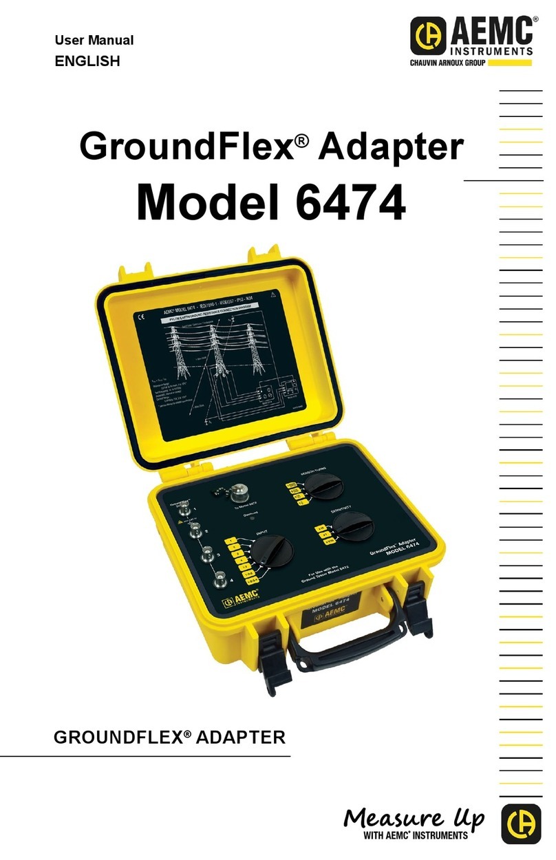
AEMC instruments GROUNDFLEX 6474 User manual

6474
User Manual
ENGLISH
GROUNDFLEX®ADAPTER
WITH AEMC
®
INSTRUMENTS

Statement of Compliance
Chauvin Arnoux®, Inc. d.b.a. AEMC®Instruments
certifies that this instrument has been calibrated using
standards and instruments traceable to international
standards.
We guarantee that at the time of shipping your
instrument has met its published specifications.
NIST traceable calibration is only possible when
the Model 6474 is connected to the Ground Tester
Model 6472.
To obtain NIST calibration (for a nominal charge), the
instrument would need to be returned to our facility,
along with your Ground Tester Model 6472.
The recommended calibration interval is 12 months
and begins on the date of receipt by the customer. For
recalibration, please use our calibration services. Refer
to our repair and calibration section at www.aemc.com.
Serial #: ________________________________
Catalog #: 2136.03
Model #: 6474
Please fill in the appropriate date as indicated:
Date Received: _________________________________
Date Calibration Due: _______________________
Chauvin Arnoux®, Inc.
d.b.a AEMC®Instruments
www.aemc.com

2
GroundFlex®Adapter Model 6474
Table of Contents
INTRODUCTION ..................................................................................... 3
1.1 International Electrical Symbols...........................................................4
1.2 DenitionofMeasurementCategories.................................................4
1.3 ReceivingYourShipment.....................................................................4
1.4 OrderingInformation ............................................................................5
1.4.1 AccessoriesandReplacementParts......................................5
GROUNDFLEX®ADAPTER ...................................................................... 6
2.1 ControlFeatures ..................................................................................6
2.2 GroundFlex®Sensor ............................................................................7
2.2.1 CalibrationofGroundFlex®Sensors .......................................8
2.3 MeasurementsinAUTOMode...........................................................10
2.3.1 PreparationoftheGroundFlex®Adapter...............................10
2.3.2 MakingaMeasurement(ResistanceofLegs) ......................12
2.3.3 OtherMeasurements ............................................................14
2.4 MANUALModeandSWEEPMode ...................................................14
2.5 TowerTestingMeasurement ..............................................................16
2.5.1 ChoosingthepositionsfortheH,Selectrodes:....................16
SPECIFICATIONS................................................................................. 24
3.1 Electrical.............................................................................................24
3.2 Mechanical.........................................................................................26
3.3 Environmental ....................................................................................26
3.4 Safety.................................................................................................26
MAINTENANCE ................................................................................... 27
4.1 Maintenance.....................................................................................27
4.2 Cleaning...........................................................................................27
RepairandCalibration.................................................................................28
TechnicalandSalesAssistance ..................................................................28
LimitedWarranty .........................................................................................29
WarrantyRepairs ........................................................................................29

GroundFlex®Adapter Model 6474
3
CHAPTER 1
INTRODUCTION
WARNING
Thesesafetywarningsareprovidedtoensurethesafetyofpersonnel.
Pleaseread and complywiththeseprecautions:
• Thisinstrumentisprotectedfromaccidentalvoltagesofnotmorethan
50VwithrespecttoearthinmeasurementCATIV.Theguaranteedlevel
ofprotectionofthisequipmentmaybecompromisedifusedinamanner
notspeciedbythemanufacturer.
• Safetyistheresponsibilityoftheoperator.
• Allmetalobjectsorwiresconnectedtotheelectricalsystemshouldbe
assumedtobelethaluntiltested.Groundingsystemsarenoexception.
• Never exceed the maximum rated voltage and current, and the
measurementcategory.
• Never exceed the protection limits, and always comply with the
conditionsandplaceofuse,indicatedinthespecications.
• Donotusetheinstrumentoritsaccessoriesiftheyappeardamaged.
• Useaccessories that haveovervoltagecategory and service voltages
greaterthanorequaltothoseoftheinstrument(CATIV50V).Useonly
accessoriesthatcomplywithsafetystandards(IEC61010-2-031&32).
• Weartheappropriateprotectivegear(insulatingbootsandgloves).
• CheckthatnoterminalisconnectedandtheswitchissettoOFFbefore
openingthedevice.
• Useonlythechargingunitsuppliedwiththeinstrumenttorechargethe
battery.
• Troubleshootingandmetrologicalvericationproceduresmustonlybe
performedbyqualied,approvedpersonnel,orthefactory.
• NOTE: Thepotentialsonthevariousrodsusedforanearthmeasurement
maybedierentifanearbyelectricalinstallationisdefectiveorcertain
weather conditions prevail (thunderstorms). It is up to the operator
to decide whether to continue or postpone measurements in these
situations.

4
GroundFlex®Adapter Model 6474
1.1 International Electrical Symbols
Signifies that the instrument is protected by double or reinforced insulation.
This symbol on the instrument indicates a WARNING that the operator must
refer to the user manual for instructions before operating the instrument. In
this manual, the symbol preceding instructions indicates that if the instructions
are not followed, bodily injury, installation/sample and/or product damage may
result.
Risk of electric shock. The voltage at the parts marked with this symbol may be
dangerous.
Ground/Earth symbol
In conformity with WEEE 2002/96/EC
1.2 Definition of Measurement Categories
CAT II: Formeasurementsperformedoncircuitsdirectlyconnectedtotheelectrical
distributionsystem.Examplesaremeasurementsonhouseholdappliancesor
portabletools.
CAT III:
Formeasurementsperformedinthebuildinginstallationatthedistributionlevel
suchasonhardwiredequipmentinxedinstallationandcircuitbreakers.
CAT IV: Formeasurementsperformedattheprimaryelectricalsupply(<1000V)such
asonprimaryovercurrentprotectiondevices,ripplecontrolunits,ormeters.
1.3 Receiving Your Shipment
Uponreceivingyourshipment,makesurethatthecontentsareconsistentwiththe
packinglist.Notifyyourdistributorofanymissingitems.Iftheequipmentappears
tobedamaged,leaclaimimmediatelywiththecarrierandnotifyyourdistributor
atonce,givingadetaileddescriptionofanydamage.Savethedamagedpacking
containertosubstantiateyourclaim.

GroundFlex®Adapter Model 6474
5
1.4 Ordering Information
NOTE: The GroundFlex®Adapter Model 6474 only operates in combination
with the Ground Tester Model 6472 Kit - 500ft.
GroundFlex®Field Kit (Model 6472 and 6474) .............................Cat. #2136.03
Includes: (Ground Tester Model 6472 Kit-500 ft (Cat #2135.54)); Model 6472, one carrying bag,
two 500 ft. color-coded leads on spools (red/blue), two 100 ft. color-coded leads (hand tied,
green/black), one 30 ft. lead (green), two 5 ft. color-coded leads (red/blue), 100/240V power
adapter with US power cord, optical USB cable, four T-shaped auxiliary ground electrodes,
set of ve spaded lugs, one 100 ft. tape measure, rechargeable NiMH battery pack, USB stick
with DataView software, ground tester workbook and user manual. GroundFlex® Adapter
Model 6474, four GroundFlex® sensors (5m), twelve color-coded rings, connection lead, two
extension leads on H reel (black/green) with color-coded alligator clips, one extra green and
black alligator clips, two BNC extension leads, calibration loop, three C-clamps, set of 2-reel
caddy’s, one inverter 12VDC to 120VAC watt (vehicle use), carrying case with wheels and
handle for meters and user manual.
1.4.1 Accessories and Replacement Parts
Bag#6-CarryingBagforGroundKits............................................. Cat. #2119.82
TapeMeasure-AEMC®(100ft) .......................................................Cat. #2130.60
Setoftwo,14.5"T-shapedAuxiliaryGroundElectrodes..................Cat. #2135.39
OpticalUSBCable............................................................................Cat. #2135.41
Replacement-ConnectionLeadforModel6472/6474.................... Cat. #2135.75
Replacement-OneBNC(15m/50ft)ExtensionLead...................... Cat. #2135.76
Replacement-Setof12,GroundFlex®Rings
(red,yellow,brown,orange) .............................................................Cat. #2135.77
Replacement-GreenExtensionLead .............................................Cat. #2135.78
Replacement-BlackExtensionLead...............................................Cat. #2135.79
Replacement-Setof3,C-clamps....................................................Cat. #2135.80
Replacement-CalibrationLoop....................................................... Cat. #2135.82
Replacement-CarryingCase ..........................................................Cat. #2135.83
Replacement-OneGroundFlex®(5m /16ft)Sensor.........................Cat. #2135.92
Replacement-SafetyAlligatorClip(black) ......................................Cat. #5000.99
Replacement-SafetyAlligatorClip(green) .....................................Cat. #5100.06
GroundFlex®Sensor10M.................................................................Cat. #2135.87
Order Accessories and Replacement Parts Directly Online
Check our Storefront at www.aemc.com/store for availability

6
GroundFlex®Adapter Model 6474
CHAPTER 2
GROUNDFLEX®ADAPTER
2.1 Control Features
50V CAT IV
1-2-3-4
1-2-3
1-2
1
2
3
4
For Use with the
Ground Tester Model 6472
GroundFlex
®
Sensor
SENSOR TURNS
SENSITIVITY
To Model 6472
Overload
INPUT
1
2
3
4
GroundFlex®Adapter
MODEL 6474
2
4
1
6
5
3
1. Inputs1through4forGroundFlex®sensors
2. ConnectorforconnectionleadtotheGroundTesterModel6472
3. OVERLOADindicator
4. SENSORTURNSselector:1,2,3or4
5. SENSITIVITYselector:x10,x1orx1/10
6. INPUTSELECTION:1,2,3,4,1-2,1-3or1-4

GroundFlex®Adapter Model 6474
7
2.2 GroundFlex®Sensor
TheGroundFlex®sensorsareplacedaroundaconductor(towerlegorpole)and
closed using a screw connector, which is part of the sensor. This closed loop
is then used to make a contact-free measurement of the current owing in the
conductor(leg)itiswrappedaround.
Thesesensorsarecurrentmeasurementclampsbutareabletoencloseobjects
thataremuchlarger.
GroundFlex®sensorsareavailableinlengthsofuptoapprox24ft(8m)andcan
beplacedaroundobjects(suchastowerlegs)uptoinapprox8ftdiameter(2.7m).
50V CAT IV
1-2-3-4
1-2-3
1-2
GroundFlex
®
Sensor
To Model 6472
Overload
INPUT
1
2
3
4

8
GroundFlex®Adapter Model 6474
2.2.1 Calibration of GroundFlex®Sensors
Calibrationisnecessaryforanewsensor,onethatisnolongeridentiedwhena
sensorhasbeenreplaced,ormorethan2lengthsofextensioncableisused.The
calibrationcoecientsarethenstoredintheModel6474.
NOTE: Do not move or touch the GroundFlex®sensor or the calibration loop
during the calibration. This could cause errors.
Startbyidentifyingeachsensorusingtheidenticationringsthataresuppliedwith
theModel6474:(1)Brown (2)Red (3)Orange (4)Yellow
• ConnectthecalibrationloopbetweenterminalsHandEoftheModel6472.
• ConnecttheModel6472and6474togetherusingtheconnectioncable.
• ConnecttheGroundFlex®sensorwiththeBrownringtoInput1oftheModel
6474,theonewiththeRedringtoInput2,theonewiththeOrangeringtoInput
3,andtheonewiththeYellowringtoInput4.
• CoiltheGroundFlex®sensorfourtimesaroundinthecalibrationloopandclose
itusingitsscrewconnector.Placetheconnectorasfaraspossiblefromthe
calibration device.
6472 6474

GroundFlex®Adapter Model 6474
9
1. Settheswitchofthe6472toSET-UP.
2. SettheSENSOR TURNSswitchto4.
3. SettheSENSITIVITYswitchtox1.
4. SettheINPUT SELECTIONswitchto1.
1-2-3-4
1-2-3
1-2
1
2
3
4
SENSOR TURNS
SENSITIVITY INPUT
5. PresstheHz/OPTIONSbutton5times.
ThedevicestartsbycomparingthecurrentIIntinjectedbythedeviceintothe
calibrationlooptothecurrentIAmeasuredbytheGroundFlex®sensor.Ifthey
aredierent,the"CAL"symbolblinkstorecommendacalibration.
x 5
4
H
E
S
x
11
AUTO
mA
m A
NOTE: To avoid measurement errors, do not touch the GroundFlex®sensor or
the calibration loop during the calibration.

10
GroundFlex®Adapter Model 6474
6. Tostartthecalibration,press2nd + START.
7. ThedevicecalculatesandstoresacalibrationcoecientfortheGroundFlex®
sensorconnectedtochannel1.
4
H
E
S
x
11
AUTO
mA
m A
Thisoperationmustberepeatedforchannels2,3and4;theINPUT SELECTION
switchmustbesettothecorrespondingpositioneachtime.
Thecalibrationvaluesarenowstoredintomemory.
After calibration, the GroundFlex® sensors must always be connected to their
respectivechannels.
NOTE: Always connect the same sensor to the same input.
2.3 Measurements in AUTO Mode
2.3.1 Preparation of the GroundFlex®Adapter
TheGroundFlex®AdapterModel6474isdesignedtobeusedonlywiththeModel
6472device.Thetwoinstrumentsmustbeconnectedusingthespecialconnection
cablesupplied.TheModel6474hasnoON/OFFbutton,andispoweredonlyby
theModel6472,viathisconnectioncable.
TheModel6474is intendedprimarilytomeasurethecurrentthatowsthrough
ahigh-voltagetowertotheground.Youcanwrapupto4legsofthetowerseach
withaGroundFlex®sensorandmeasurethecurrentowingtoearththrougheach
ofthelegsorthroughseverallegs.
1. SettherotaryfunctionswitchtoGroundFlex®ontheModel6472.
WhenyouconnecttheGroundFlex®AdapterModel6474tothe6472,aself-
testwillbegin.Duringthistest,theOVERLOADchecklightonthe6474islit.
2. Connecttherequirednumberofsensorstochannels1,2,3,and/or4.

GroundFlex®Adapter Model 6474
11
NOTE: • The sensors have arrows to indicate a direction.
• All sensors should face the same direction.
(clockwise or counter-clockwise around the tower legs)
• All sensors should have the same number of wraps.
• Sensors should encircle both leg AND ground system.
6474
To the Model 6472
3. OntheModel6474,settheINPUT selectionswitchaccordingly.Youcanmea-
surethe currentowingthrough one GroundFlex®sensor (1, 2,3,or 4),or
throughseveralsensors(1,2or1,2,3),orthroughallofthesensors(1,2,3,
4).
4. Select how many times the sensor is wrapped around the conductor to be
measured(from1to4turns)usingtheSENSOR TURNSselectionswitch.
NOTE: To increase measurement sensitivity, we recommend when possible,
wrapping a maximum number of turns (up to 4) around the structure.
5. SettheSENSITIVITYswitchtothedesiredsensitivity:x1/10,x1,orx10.The
choiceofsensitivitydependsontheexpectedcurrentvalue.Asaprecaution,
alwaysstartwiththelowestsensitivity,x1/10,andincreaseitasneeded.

12
GroundFlex®Adapter Model 6474
2.3.2 Making a Measurement (Resistance of Legs)
1. PlaceauxiliaryelectrodesH (Z) and S (Y)onoppositesidesofthetower,as
farawayaspossible(100-150ft)and,ifpossible,perpendiculartothehigh-
voltageline(depthisnotimportant).Thiswilleliminateinterferencewiththe
measurementby stray voltages or currents induced underthehigh-voltage
line.
NOTE: The H (Z) and S (Y) electrodes can be placed in the same direction
if necessary. In this case, the S (Y) electrode should be placed at 62% the
distance of H (Z).
2. In order to avoid electromagnetic interference, it is best to unwind the full
lengthofeachcablefromthereel,tokeepthecablesasfarapartaspossible
ontheground,takingcarenottoformloops,andtoavoidplacingthecables
nearorparalleltometallicconductors(cables,rails,fences,etc.).Eectsof
interferencearemeasuredinmilli-ohms.
3. Connectthese auxiliary electrodes to the terminals H (Z) and S (Y) onthe
Model6472'sfrontpanel.
4. Important: TheterminalsES (Xv) and E (X)mustbeconnectedtoaconduct-
ingmetallicpartofthetowerlocatedabovetheGroundFlex®sensors.This
ensuresmeasurementofthecurrentowingdownwardandtowardstheearth
(otherwise,youwouldmeasurethecurrentowingupward,fromtheearthto
thetopofthetower).
Thiswilltelltheconditionoftheoverheadgroundconductor.
5. Connect the required number of GroundFlex® sensors to channels 1, 2, 3,
and/or4(thechannelsforwhichtheyarecalibrated)andplacetheGround-
Flex®sensorsaroundthelegsofthetower.
NOTE: The direction of coiling of the sensors around tower legs have no
effect on the measurement, but all of the GroundFlex®sensors must be
coiled in the same direction and have the same orientation (check arrow
direction on the sensor) and they must all have the same number of turns.
Sensors should encircle both leg AND ground system.

GroundFlex®Adapter Model 6474
13
E
S
H
RS
RH
ES
1
2
3
4
6474
6472
Overhead earth wire
High-voltage
lines
4 GroundFlex®sensors
connected with the
same orientation
WARNING: If the GroundFlex®Adapter Model 6474 is connected to the earth
tester, the earth potential connected to the terminals E (X) and ES (Xv) will
also be present at the BNC connectors of the GroundFlex®sensors and at the
connecting cable between the adapter and tester. Whenever any doubt exists
about this earth potential, the user should proceed to a voltage measurement
using the S (Y) and ES (Xv) terminals of the tester.
1. Setthe3switches(Inputs,TurnsandSensitivity)oftheGroundFlex®Adapter
accordingtotheconnectionmade.
2. StartthemeasurementbypressingtheSTART/STOPbutton.
1
AUTO
k
Ω
mA
V
H
S
ES
E
S
x
12
Todisplaythemeasurementparameters,pressDISPLAY several times.

14
GroundFlex®Adapter Model 6474
Thedevicedisplaysthefollowingparameters:
RSEL,US-ESanditsfrequency,ISEL,R-Act(RPASS),U-Act(US-ESanditsfrequency,
UH-Eanditsfrequency),I-Act(ISELanditsfrequency).
TomeasuretheresistancesofelectrodesH (Z) and S (Y),oriftheresistanceof
theelectrodesistoohigh,startthemeasurementbyalongpress(approx2sec)of
theSTART/STOPbutton(youwillheara2ndbeep).
RH,RS,UH-E,IH-Ewillbedisplayed.
2.3.3 Other Measurements
AsexplainedinStep4onthepreviouspage,terminalsES (Xv) and E (X)mustbe
connectedtoametallicpartofthetowerabovetheGroundFlex®sensor in order to
measurethecurrentowingISELdownwardthroughthesensortowardstheearth
tomeasuregroundresistanceoftheleg.
IfconnectionsES (Xv) and E (X)areplacedbelowtheGroundFlex®sensor,the
lattermeasuresthecurrentowingtowardsthetopofthetowerviatheoverhead
groundconductoratitstop,andyoucaninthiswayevaluatethequality of this
overhead ground conductor.
You can even make this measurement without moving the contacts of ES (Xv)
and E (X) on the tower by simply passing the 2 connecting cables through the
GroundFlex®sensor.ThecurrentinconnectingcableE(X) andthecurrentthrough
thelegofthetowerthencanceleachotherout.
Youcanalsomeasureany leakage currents(I-Act)owingthrougheachlegof
thetowerinnormaloperationofthehigh-voltageline.Ifyounddierentleakage
currentsineachleg,buttheycanceloutwhenaddedtogether,youcanconclude
thatthesecurrents,inducedbytherotatingeldofthehigh-voltagelines,indicate
an earthing faultofthetowervia the overhead ground wire at the tip of the
mast.
2.4 MANUAL Mode and SWEEP Mode
Use the Hz/OPTIONS button and ► button to change to MANUAL mode. The
followingparameterscanbemodied:
• 128Hzblinks Changethetestfrequency
• Testvoltageblinks Switchbetween10,16,32and60V
Youcanalsoperformafrequencysweepandasmoothing.

GroundFlex®Adapter Model 6474
15
Inthesweepmode,themeasurementscanbemadeatfrequenciesupto5kHz.
Onasingletower,frequenciesintheorderof5kHzdonotalwaysentailinductive
eects, but the "current loops" formed by the adjacent towers and the return
channelthroughthegroundmayresultininductancesthatcanbedetectedonly
athighfrequencies.
Anequivalentdiagramofthecomponentsformingthiscircuitisasfollows:
Point of injection
of the current
Overhead
earth wire
LLL
Rpylon
Next pylon
to the left
Pylon
measured
Next pylon
to the right
A measurement in sweep mode (SWEEP) of an installation like this having 10
towersgivesthefollowingresultsassuminganearthresistanceRpylon of10Ωfor
eachtowerandaninductanceLof550µH for the link via the overhead ground
conductoratthetipofthetowers:
Impedance of the towers
0
2
4
6
8
10
12
14
16
0100020003000 4000 5000
F (Hz)
Z (ohm)
MeasurementofatowerearthimpedancewithGroundFlex®
sensors
Conventional4polemeasurement
Measurementintothetopofatower(iterativenetworkimpedance)

16
GroundFlex®Adapter Model 6474
2.5 Tower Testing Measurement
1. ConnectthegreenCurrent(E)andblackVoltage(ES)testleadstothe
groundingsystemtobetestedusingseparatecables.Connectionpoints
shouldbesidebysideandabovetheGroundFlex®(Rogowski)coilwhen
testingtowerlegresistanceand/orimpedance.
Figure 1
2. WraptheGroundFlex®coilsaroundthetower'sleg(s).Byincreasingthe
numberofturnsaroundthetower'sleg(s), theresultingmeasurementswill
bemorerobust. Allcoilsmusthavethesamenumberofturnsaroundeach
towerleg.
3. Installallcoilsinthesamerotationaldirection,eitherclockwiseor
counterclockwise.ThecoaxcablesontheGroundFlex®sensorshavearrows
toindicatetherotationaldirectionthatmustbeconsistentbetweentower
legs.Ontowerswith3or4legs,thesensorsmustbeinsequencefromone
legtothenext.
Figure 2
2.5.1 Choosing the positions for the H, S electrodes:
1. Ifpossible,positiontheHandSelectrodes90°totheHighVoltage(HV)line,
andplaceonetotheleftandtheothertotherightwithrespecttotheHV
transmissionline.Ifthisisnotpossible,stayatleast30°oparalleltotheHV
line.Theminimumdistanceshouldbe150–300ft(50-100m).Neverplace
anelectrodewithintheminimumdistancefromtheHVlineand/orparallelto
theHVline.
2. ConnecttheHelectrodeusingthered(H)leadandtheSelectrodeusingthe
blue(S)lead(seeFigure2).

GroundFlex®Adapter Model 6474
17
NOTE:TheresistancefortheHandSelectrodestoearthshouldeachbebelow
1kΩtoensuregoodtestresults.
Figure 3
3. Forthemostaccuratemeasurements,rollthecablecompletelyoutto
eliminateanyinductanceproblemsinlocationswithhighoverheadenergy
fromtheHVline.Normallyerrorsareinthemilliohmregionwhenthecables
arenotfullyremovedfromthespool.
4. Conrmthattheumbilicalcableconnectionbetweenthe6472and6474is
secure.Checkthepositionoftherotaryswitches(Input,SensorTurnsand
Sensitivity)onthe6474tobesuretheymatchthetestrequirements(see
Figure4).
5. Makesurethenumberofturnsbetweentowerlegsarethesame.The
numberofturnsmustcorrespondtothenumberofturnsusedontheinstalled
GroundFlex®coilsoneachtowerleg.
Figure 4
6. Useinputswitchposition"1-2-3-4"formeasurementofthetotalpylonearth
currentonfourlegtowers.Usethecorrespondingswitchpositionfor2(1-2)
and3(1-2-3)legtowers.
7. Startthetestwithx10amplication.
8. Turntherotaryswitchonthemodel6472totheGroundFlex®position.The
6474amplierwillturnonafterthe6472ispoweredonandthecalibration
oftheconnectedGroundFlex®sensorswillbeveried.TheOverloadLED
willcomeonforafewsecondsduringpowerup.IfthisLEDisashing
continuouslyandthe6472isbeepingcontinually,thenthecurrentinthe
GroundFlex®sensor(s)aretoohighfortheselectedamplication.Reduceto
X1andthentoX1/10ifnecessary.Ifitisstillpresentinthe1/10position,then
reducethenumberofturnsoftheGroundFlex®sensors.

18
GroundFlex®Adapter Model 6474
First check (see Figures 5, 6, 7, and 8):
1. PresstheDISPLAYbuttonuntilU-Act.andUS-ESorUH-Eisshown.U-Act.
referstoliveactualvoltage.US-ESequalsmeasuredvoltagebetweenSand
ES. DisturbancevoltagemeasurementsontheSProbeandtheHAuxiliary
electrodewillruncontinuouslyaslongasatesthasnotbeeninitiatedwith
theSTARTbutton.
2. PresstheDISPLAYkeyagainuntilU-Act.andUH-Eisshown.UH-Eequals
themeasuredvoltagebetweenHandE.ThefrequencyofUS-ESorUH-E
appearswhenthecorrespondingvoltageishigherthan0.1V.Themeasured
voltageiscausedbythecurrentowingthroughthetowerintotheEarth.
3. CheckifthevaluesforUH-EandUS-ESareequal.WhenUH-EequalsUS-
ES,theelectrodesareplacedfarenoughfromthepotentialinuenceofthe
towerlegs.
4. Ifoneofthevaluesissmallerthantheothervalue,youshouldrepositionthe
electrodethatshowsthesmallervoltagefurtherawayfromtheHV-lineand
checkUS-ESandUH-Eagain.
5. PresstheSTART-buttonwhenbothmeasurementsareequaltoeachother
forareliableactivemeasurement.WhenbothUS-ESandUH-Earecloseto
zero,thentheHV-lineisnotinserviceortheoverheadgroundconductoris
completelycorrodedordisconnected.Inthiscase,thetotalpyloncurrentwill
bealsonearlyzero.
6. PresstheDISPLAYbuttonuntilISELappears.Thisisthetotalpylonearth
currentandismeasuredbythe4GroundFlex®sensors(channels1-2-3-4
selectedfora4legtower).
Figure 7 (model 6472)
Figure 6
Figure 5

GroundFlex®Adapter Model 6474
19
7. Next,presstheDISPLAYbuttonuntilRPASSappears.Aleakagecurrent
I-SEL,wheninducedinthepylon,producesavoltagedropUS-ES(potential
dierencetoEarth)ontheearth-resistanceofthepylon.OncetheI-SEL
andUS-ESvaluesareknown,the6472cancalculateRPASS(passive
earthresistance).Ithastheadvantageofbeingmeasuredatthenominal
frequencyofthenetworkbutisalsoinuencedbytheloaductuationsinthe
networkandbythepotentialinuenceoftheHV-line.Whenthetowerearth
resistanceisactivelymeasuredandisnearlyequaltoRPASS,theresultwill
bereliable;otherwise,thepotentialrelationshipduringtheactiveandpassive
measurementwillbedierent.
Figure 8 (model 6472)
Second check (See Figures 9):
1. CurrentsinthetowerlegsaremeasuredcontinuouslyaslongastheSTART-
buttonhasnotbeenpressed.Switchthemodel6474toINPUT1.SelectISEL
on6472withDISPLAYbutton.
Figure 9
2. Checkthecurrentineachtowerlegbyswitchingthrougheachchannelin
sequencewhilenotingthemeasurementsofeach.Youcanndcorroded
and/ordisconnectedearthconnectionsasindicatedbyreadingsthatshowno
currentow.
3. Checkthesumofalllegcurrentchannels.Ifthetotalisapproximatelyequal
tothesumoftheallindividuallegcurrents,thenthestaticwire(overhead
groundconductor)isbondedtothetowerproperly.Ifnot,thisconnectionis
probablycorrodedandonlyasmallcurrentwillbeowinginthetowerlegs,
whichwillbeinducedinthetowergrounding.Thesumwillbeverylow,but,
despitethat,singlecurrentsmaybehigherbecausetheycanowindierent
directions.ThemeasurementofRPASSforindividuallegshasnovalue.
Evenwhenindividuallegsarenotconnectedtogether.Belowgroundlevel,
theywillstillinuenceeachother.
Other manuals for GROUNDFLEX 6474
2
Table of contents
Other AEMC instruments Adapter manuals
Popular Adapter manuals by other brands

Dolphin
Dolphin MXH94 Series user guide

Devolo
Devolo Magic 1 WiFi 2-1 manual
Digi
Digi Connectware Series Hardware Installation and Cable Guide
Allied Telesis
Allied Telesis AT-2712FX Installation and user guide

NETGEAR
NETGEAR HDX111 - Powerline HD Plus Ethernet Adapter datasheet
Sling Media
Sling Media Slinglink quick start guide
