manuals.online logo
Brands
  1. Home
  2. •
  3. Brands
  4. •
  5. Aereco
  6. •
  7. Fan
  8. •
  9. Aereco V2A User manual

Aereco V2A User manual

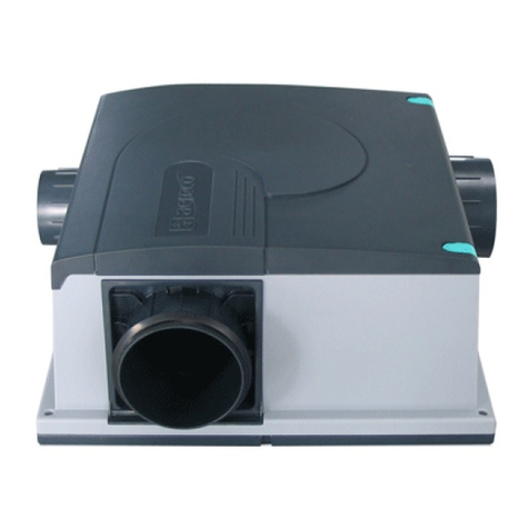
INSTALLATION INSTRUCTIONS - NOTICE D’INSTALLATION
ENGLISH FRANÇAIS DEUTSCH
V2A
ACOUSTIC FAN FOR 2 WET ROOMS VENTILATEUR ACOUSTIQUE 2 SANITAIRES SCHALLGEDÄMMTES LÜFTUNGSGERÄT
FÜR BIS ZU 2 SANITÄRRÄUME
Consommation d’énergie spécifique* : -25.6 kWh/(m².an)
Débit maximum : 80 m3/h
Pression maximum : 80 Pa
Puissance acoustique @ 20 m3/h : 33 dB(A)
Puissance maximum : 13 W
Alimentation (réf. V2A041) :100 VAC +/- 10%
Alimentation (réf. V2A032) : 230 VAC +/- 10%
Fréquence : 50 Hz ou 60 Hz
Utilisation : en intérieur
Stockage : de -20°C à + 55 °C
Température de fonctionnement : de +5°C à +40°C.
Degré de pollution : 2
Appareil entièrement protégé par une double isolation.
Specific Energy Consumption* : -25.6 kWh/(m².a)
Maximum airflow : 80 m3/h
Maximum pressure : 80 Pa
Sound level @ 20 m3/h : 33 dB(A)
Maximum power : 13 W
Supply (ref. V2A041) : 100 VAC +/- 10%
Supply (ref. V2A032) : 230 VAC +/- 10%
Frequency : 50 Hz or 60 Hz
Use : indoor
Storage temperature : from -20°C to + 55 °C
Working temperature : from +5°C to +40°C.
Pollution degree : 2
Fan fully protected by a double insulation.
Spezifischer Energieverbrauch* : -25.6 kWh/(m².a)
Max. Luftmenge : 80 m3/h
Max. Druck : 80 Pa
Schalldruckpegel Lp @ 20 m³/h / @ 80 m³/h (r = 2m):
32 / 33 dB(A)
Max. E-Leistung : 13 W
Anschluss (ref. V2A041) : 100 VAC +/- 10%
Anschluss (ref. V2A032) : 230 VAC +/- 10%
Frequenz : 50 Hz oder 60 Hz
Anwendungsbereich : innen
Lagerungstemperatur : von -20°C bis + 55 °C
Verwendungstemperatur : von +5°C bis +40°C.
Gerät durch eine Doppelisolierung komplet geschützt.
* : Following the implementation of the European
Directive 2009/125 / EC, the values indicating the
specific energy consumption are guaranteed only if
the ventilation unit is installed as a ducted type and
with at least two local demand control units.
* : Dans le cadre de la directive Européenne 2009/125/CE,
les valeurs indiquant la consommation d’énergie spécifique ne
sont garanties que dans le cas où l’unité de ventilation soit
de type centralisée et installée avec au moins deux bouches
d’extraction à débit modulé.
* : Im Rahmen der Europäischen Richtlinie 2009/125/EG
werden die Werte für den spezifischen Energieverbrauch
nur gewährleistet, wenn eine zentrale Lüftungsanlage
mit mindestens zwei feuchtegeführten Abluftelementen
installiert ist.
2 AERECO – TF3486_E
ENGLISH FRANÇAIS DEUTSCHV2A ENGLISH FRANÇAIS DEUTSCHV2A
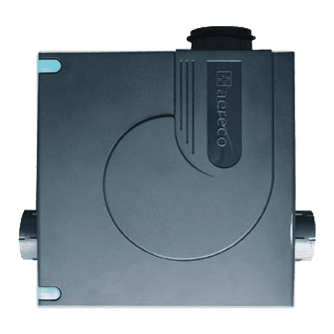
Le V2A est un ventilateur
silencieux pouvant être
installé directement à
l’intérieur du logement dans
l’espace habité.
Il permet de raccorder jusqu’à 2
bouches VMC à section variable
(hygroréglable, à détection de
présence, etc) comme la serie
AERECO AH80.
Domaine d’emploi :
Ventilation des pièces
techniques (salle de bain et wc
principalement) dans l’habitat
ou le tertiaire.
- Travaux : neuf et rénovation.
- Lieu d’installation : Dans
un placard, un faux plafond
ou au mur, en salle de bain,
wc, couloir, ou autre pièce
intérieure.
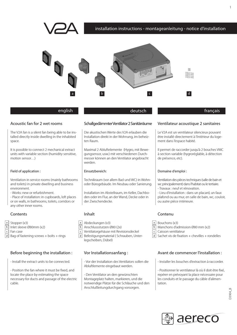
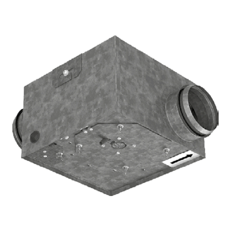
The V2A fan is a silent fan
being able to be installed
directly inside dwelling in the
inhabited space.
It is possible to connect 2
VMC extract units with variable
section (humidity sensitive,
motion sensor…) such as
AERECO AH80 series.
Field of application :
Ventilation in service rooms
(mainly bathrooms and toilets)
in private dwelling and business
environment.
- Works : new or refurbishment.
- Place of installation : in
cupboards, loft places or on
walls, in bathrooms, toilets,
corridors or any other inner
rooms.
Die akustischen Werte des
V2A erlauben die Installation
direkt in der Wohnung, im
beheizten Raum.
Maximal 2 Abluftelemente
(Hygro, mit Bewegungsensor
usw.) mit verschiedenen
Durchmesser können an das
Lüftungsgerät angebracht
werden wie serie AERECO
AH80.
Einsatzbereich:
Technikraum (vor allem Bad
und WC) in Wohn- oder
Bürogebäude. Im Neubau oder
Sanierung.
Installation im Abstellraum, im
Keller, Dachboden oder im Flur,
an der Wand, Decke oder in der
Zwischendecke.
A
D
B
C
A. Caisson ventilateur
B. Manchons d’admission
Ø80mm (x2)
C. Bouchons (x3)
D. Sachet vis de fixation + chevilles
+ rondelles
A. Fan case
B. Inlet sleeve Ø80mm (x2)
C. Stopper (x3)
D. Bag of fastening screws + bolts
+ rings
A. Ventilatorgehäuse mit
Revisionsdeckel
B. Anschlussstutzen Ø80 (2x)
C. Abdeckungen (x3)
D. Befestigungsmaterial (Schrauben,
Unterlegscheiben, Dübel)
AERECO – TF3486_E 3
DEUTSCHFRANÇAISENGLISH
ATTENTION
• L’installation de ce produit doit être eectuée par
un technicien qualifié.
• Fabricants et distributeurs declinent toute
responsabilité en cas d’utilisation non conforme du
produit.
• La protection de ce produit peut être compromise
si le produit est utilisé d’une autre manière que
celle spécifiée dans cette notice.
• Cet appareil peut être utilisé par des enfants
âgés d’au moins 8 ans et par des personnes
ayant des capacités physiques, sensorielles ou
mentales réduites ou dénuées d’expérience ou
de connaissance, s’ils (si elles) sont correctement
surveillé(e)s ou si des instructions relatives à
l’utilisation de l’appareil en toute sécurité leur ont
été données et si les risques encourus ont été
appréhendés. Les enfants ne doivent pas jouer
avec l’appareil.
• Le nettoyage et l’entretien par l’usager ne
doivent pas être eectués par des enfants sans
surveillance.
SÉCURITE ÉLECTRIQUE
• Ce symbole placé sur la trappe de connection
indique un danger électrique lié à la présence
de 230 VAC (en version 230 VAC). Il est donc
indispensable de couper l’alimentation avant de
démonter la trappe !
• Le V2A doit être branché directement au tableau
électrique basse tension.
• Afin d’éviter un danger dû au réarmement
intempestif du coupe-circuit thermique,
cet appareil ne doit pas être alimenté par
l’intermédiaire d’un interrupteur externe, comme
une minuterie, ou être connecté à un circuit qui est
régulièrement mis sous tension et hors tension par
le fournisseur d’électricité.
AVANT DE COMMENCER L’INSTALLATION :
• Installer les bouches d’extraction à raccorder.
• Positionner le ventilateur là où il doit être fixé,
repérer en prévoyant la place nécessaire pour les
conduits et le passage du câble d’alimentation.
WARNINGS
• Installation of this product must be carried out by
a qualified technician.
• Manufacturer and distributors decline
responsibility in the event of non conformed use of
the product.
• If the product is used in a way not specified in
this document, the protection of the product can be
compromised.
• This appliance is not intended for use by persons
(including children over 8 years old) with reduced
physical, sensory or mental capabilities, or lack of
experience and knowledge, unless they have been
given supervision or instruction concerning use
of the appliance by a person responsible for their
safety. To avoid any risk, do not allow them to play
with the appliance.
• Cleaning and maintenance by the user should
not be done by unattended children.
ELECTRICAL SECURITY
• This symbol placed on the connection access
panel indicates an electric danger due to the
presence of 230 VAC (in version 230 VAC). It
is thus essential to cut o the supply before
dismounting the access panel.
• The V2A fan must be connected directly in the
low-tension electric control panel.
• In order to avoid a hazard due to inadvertent
resetting of the thermal cutout, this appliance must
not be powered through an external switching
device such as a timer, or connected to a circuit
that is regularly switched on and o by the power
provider.
BEFORE BEGINNING THE INSTALLATION,
PLEASE :
• Install the extraction units to be connected,
• Position the fan where it must be fixed, and
locate the place by estimating the space necessary
for ducts and passage of the electric cable.
ACHTUNG
• Die Montage dieses Ventilators darf nur von einer
Fachfirma durchgeführt werden.
• Hersteller und Vertreiber haften nicht bei nicht
gerätekonformer Nutzung des Produkts.
• Der Geräteschutz kann beeinträchtigt werden,
wenn das Produkt nicht anleitungsgemäß
verwendet wird.
• Das Gerät darf NICHT von Kindern (mindestens
8 Jahre alt) oder Personen mit reduzierten
physischen, sensoriellen oder geistigen Fähigkeiten
benutzt werden oder von solchen, deren Erfahrung
und Kenntnisse hierfür nicht ausreichend
sind, es sei denn, sie haben die diesbezüglich
erforderlichen Anweisungen von einer, für ihre
Sicherheit verantwortlichen Person erhalten.
• Montage, elektrischer Anschluss, Inbetriebnahme
und Wartung des Gerätes, darf nur durch eine
entsprechend ausgebildete Fachkraft erfolgen.
ELEKTRISCHE SICHERHEIT
• Dieses auf der Anschlussklappe sichtbare
Zeichen besagt eine Spannung von 230 VAC.
• Vor dem önen der Anschlussklappe ist der
Ventilator Spannungsfrei zu schalten und vor
unbeabsichtigtem Wiedereinschalten zu sichern.
• Um Gefahren durch ein versehentliches
Zurücksetzen des Temperaturbegrenzers zu
vermeiden, darf dieses Gerät nicht durch ein
externes Schaltgerät, wie eine Zeitschaltuhr,
mit Strom versorgt oder an einen Stromkreis
angeschlossen werden, der vom Stromanbieter
regelmäßig an- und abgeschaltet wird.
VOR INSTALLATIONSANFANG :
• Vor der Installation des Ventilators sollen die
Abluftlemente eingebaut werden.
• Den Ventilator an den gewünschten
Montageplatz halten, markieren, und die
notwendige Plätze für die Schläuche und den
Anschlußleitungdurchgang vorsorgen.
4 AERECO – TF3486_E
ENGLISH FRANÇAIS DEUTSCHV2A ENGLISH FRANÇAIS DEUTSCHV2A
1. Vérifier la bonne mise en
place de la mousse de
chaque accessoire.
1. Check the good
installation of the foam of
each accessory.
1. Die richtige Position des
Schaummaterials bei
jedem Zubehör prüfen.
x4 CLIC !
OK !NO
2. Enter connection sleeves
and stoppers on the 4
openings of the case.
2. Clipper les manchons
d’admission et les
bouchons sur les 4
ouvertures du caisson.
2. Die Anschlussstutzen
und Abdeckungen auf
die 4 Gehäuseönungen
klicken.
5. Withdraw the lid by
drawing the 2 green clips
5. Retirer le couvercle en
tirant les 2 clips verts.
5. Die 2 grünen Clips
ziehen und den Deckel
abnehmen.
3. Withdraw the base of the
case : begin by the angles.
3. Retirer le socle du caisson:
déclipper d’abord les
angles.
3. Zum Befestigen des
Lüftungsgeräts den Sockel
des Gehäuses abnehmen,
dabei die Ecken zuerst
abklicken.
4. Fix the base using the
provided 4 screws + rings
(+ bolts if necessary).
Tighten moderately (be
careful not to crush the
silent block).
4. Fixer le socle à l’aide
des 4 vis + rondelles
fournies (+ chevilles si
nécessaires).
Serrer modérément (ne
pas écraser le silent bloc)
4. Den Sockel mit den 4
mitgelieferten Schrauben,
Unterlegscheiben und
Dübeln (wenn notwendig)
befestigen.
Achtung: die Schrauben
nicht zu fest anziehen,
damit die Grundplatte
nicht ausbricht.
AERECO – TF3486_E 5
ENGLISH FRANÇAIS DEUTSCHV2A
6. Retirer la cale.6. Withdraw the hold. 6. Den Styroporkeil
entnehmen.
7. Unscrew the lid of the
electrical case by using a
PH1 screwdriver.
7. Dévisser le couvercle du
boîtier électrique à l’aide
d’un tournevis PH1.
7. Den Deckel des
Anschlusskastens mit
einem kleinen
Kreuzschlitzschrau-
bendreher abnehmen.
Do not connect the electrical
supply network as long as
the fitting is not completely
finished.
Ne pas raccorder au réseau
électrique tant que le montage
n’est pas totalement terminé !
An Elektriknetz nicht
anschliessen bevor die
Montage fertig ist.
10. Block the cable in the
cleat and thread the
cable-shifter in the lid of
the case.
10. Bloquer le câble dans
le serre-câble et enfiler
le passe-câble dans le
couvercle du boîtier
10. Die Anschlussleitung
mit der Zugentlastung
befestigen und die
Kabeldurchführung in den
Gehäusedeckel einfädeln.
8. Thread the cable-shifter
on the feeder (feeder not
provided).
8. Enfiler le passe-câble sur
le cordon d’alimentation.
(cordon non fourni).
8. Die Anschlussleitung (wird
Bauseits gestellt) durch
die Kabeldurchführung
einfädeln.
9. Connect the feeder to the
corresponding terminals.
L Phase
Ground
N Neutral
9. Raccorder le cordon
d’alimentation aux bornes
correspondantes.
L Phase
Terre
N Neutre
9. Die Anschlußleitung an die
entsprechenden Klemmen
anschliessen.
L Phase
Masse
N Neutral
6 AERECO – TF3486_E
ENGLISH FRANÇAIS DEUTSCHV2A ENGLISH FRANÇAIS DEUTSCHV2A
OUTPUT 1A2CV
CLIC !
11. Sortie 12 VAC : raccorde
si nécessaire 1 ou 2
bouches à débit de pointe
électrique.
Utiliser alors la carte
alimentation réf. AEA878
(transformateur 12 VAC -
8 VDC)
11. Output 12 VAC : Connect
if necessary 1 or 2 extract
units with peak airflow
supply.
Then use the transformer
ref. AEA878 (transformer
12 VAC - 8 VDC)
11. Ausgangsspannung im
Anschlusskasten 12 VAC
zum Anschluss von einem
oder zwei Abluftelemente
mit Stoßlüftungsfunktion.
In diesem Fall müssen in
die Abluftelemente die
Netzstabilisatoren ANA
12 V zusätzlich eingesetzt
werden.
12. Close and screw up the lid
of the electric case.
12. Refermer et revisser
le couvercle du boîtier
électrique
12. Den Deckel des
Anschlusskasten wieder
verschließen.
15. Check the installation
of the fixing clips in the
middle on each side
15. Vérifier la mise en place
des clips de fixation au
milieu de chaque côté.
15. Darauf achten, dass das
Lüftungsgerät auf dem
Sockel in der Mitte richtig
einrastet.
13. Close the lid 13. Refermer le couvercle. 13. Den Deckel des
Lüftungsgeräts wieder
zumachen.
14. Fix the box on its base 14 Clipper le caisson sur son
socle.
14. Das Ventilatorgehäuse auf
seinen Sockel klicken.
AERECO – TF3486_E 7
ENGLISH FRANÇAIS DEUTSCHV2A
x4
16. Fixer le caisson sur son
socle (4 vis fournies) à
l’aide d’un tournevis PZ 2
16. Fix the case on its base
(4 provided screws) using
a PZ2 screwdriver.
16. Das Gehäuse mit den
mitgelieferten Schrauben
auf dem Sockel
befestigen.
17. Carry out the holes for the
passage of the ducts in
front of the inlet and outlet
sleeves.
Take care not to insert
debris and dust in the
motor !
17. Face aux manchons
d’admission et
d’extraction, réaliser les
trous de passage des
conduits.
Veiller à ne pas faire entrer
de débris et poussières
dans le moteur !
17. Die Wanddurchbrüche
in der Nähe der
Ansaugstutzen und
des Fortluftstutzens
durchführen.
Beachten Sie, dass
keine Fremdkörper (z. B.
Staub oder Steine) in den
Ventilator eindringen.
20. Connect the 2 extract units
and the extract grille: the
fan is ready to operate !
20. Raccordez les 2 bouches
d’extraction et la grille de
sortie : Le ventilateur est
prêt à fonctionner !
20. Die Abluftelemente
und das Fortluftgitter
anschließen. Das
Lüftungsgerät ist jetzt
betriebsbereit.
18. If you connect ducts Ø
100mm, encase the
accessory ref. SE3203
on the inlet sleeve. If you
connect ducts Ø 80mm,
no accessory is necessary
18. Si vous raccordez des
conduits Ø100mm,
emboîtez l’accessoire réf.
SE3203 sur le manchon
d’admission. Si vous
raccordez des conduits
Ø80mm, aucun accessoire
n’est nécessaire.
18. Wenn Sie vor den
Abluftelementen
Wickelfalzrohr mit Ø100
/ Ø 125 anschließen
wollen, müssen Sie den
Anschlussstutzen AS 100
/ AS 125 mitbestellen.
An den Fortluftstutzen
kann nur ein
Wickelfalzrohr Ø100
angeschlossen werden.
19. Encase the duct then
make it integral by using
a special AV adhesive.
Do the same for the other
inlet and outlet ducts.
19. Emboîter le conduit puis
solidariser à l’aide d’un
adhésif spécial VMC.
Faire de même pour
l’autre admission puis
l’extraction.
19. Wickelfalzrohre auf die
Stutzen stecken und mit
Alu-Klebeband abdichten.
8 AERECO – TF3486_E
ENGLISH FRANÇAIS DEUTSCHV2A ENGLISH FRANÇAIS DEUTSCHV2A
1. Before any intervention,
cut o the fan supply
from the circuit breaker.
1. Avant toute intervention,
coupez l’alimentation
du ventilateur du
disjoncteur.
1. Unterbrechen Sie vor
jedem Eingri die
Stromversorgung der
Lüftungseinheit.
WARNING CONCERNING
REPLACEMENT OF THE
FUSE ON A PRODUCT
ALREADY INSTALLED:
·The replacement must be
carried out by a qualified
technician
·The manufacturer and the
distributor decline any
responsibility in the event
of a non conformity use of
the product
·In the event of non
respect of these
recommendations, the
protection of the product
can be compromised.
AVERTISSEMENT
CONCERNANT LE
REMPLACEMENT DU
FUSIBLE SUR UN PRODUIT
DÉJÀ INSTALLÉ :
·Le remplacement doit être
eectué par un technicien
qualifié.
·Le fabricant et le
distributeur déclinent
toute responsabilité en
cas d’utilisation non
conforme du produit.
·En cas de non-respect de
ces recommandations, la
protection du produit peut
être compromise.
WARNUNG BEI
AUSTAUSCH DER
SICHERUNG AN EINEM
BEREITS INSTALLIERTEN
PRODUKT:
·Der Austausch muss
von einem qualifizierten
Techniker durchgeführt
werden.
·Der Hersteller und der
Händler lehnen jede
Verantwortung im Falle
einer nicht konformen
Verwendung des Produkts
ab.
·Bei Nichtbeachtung dieser
Empfehlungen kann der
Schutz des Produkts
beeinträchtigt werden.
2. Withdraw the lid. 2. Retirez le couvercle. 2. Entfernen Sie den Deckel.
3. Unscrew (1 screw) and
withdraw the trap door of
the electrical case.
3. Dévissez (1 vis) et retirez la
trappe du boîtier électrique.
3. ösen Sie die Schraube und
ziehen Sie die Falltür des
elektrischen Gehäuses
heraus.
REPLACEMENT FUSE FOR V2A
REMPLACEMENT DU FUSIBLE POUR V2A
ERSATZSICHERUNG FÜR V2A
AERECO – TF3486_E 9
ENGLISH FRANÇAIS DEUTSCHV2A
6. Screw the fuse holder.
4. Take out the fuse holder. 4. Sortez le porte-fusibles. 4. Nehmen Sie den
Sicherungshalter heraus.
7. Fix the trap door (1 screw).
5. Unscrew the fuse holder
and replace with a new
fuse 5x20mm, delayed:
class T, 200mA, 250V.
8. Put the lid back.
9. Engage the circuit breaker
in order to supply the fan
and check its operat.
5. Dévissez le porte-fusibles
et remplacez-le par un
nouveau fusible 5x20mm,
temporisé : type T,
200mA, 250V.
6. Vissez le porte-fusibles.
7. Fixez la trappe (1 vis).
8. Remettez le couvercle.
9. Réarmez le disjoncteur afin
de mettre le ventilateur
sous tension et de vérifier
son fonctionnement
5. Schrauben Sie den
Sicherungshalter ab
und ersetzen Sie die
Sicherung durch eine neue.
5x20mm Sicherung,
Zeitverzögerung: Typ T,
200mA, 250V.
6. Schrauben Sie den
Sicherungshalter fest.
7. Befestigen Sie die Falltür
(1 Schraube)
8. Setzen Sie den Deckel
wieder auf.
9. Schalten Sie den
Leistungsschalter ein, um
den Lüfter zu versorgen
und überprüfen Sie dessen
Funktionierung
Note: Colours of wires may vary according to the V2A version. Pictures not contractual.
Remarque : Les couleurs des fils peuvent varier selon la version du V4A. Photos non contractuelles.
Hinweis: Die Farben der Drähte können je nach V4A-Version variieren. Bilder nicht verträglich.
TF3486_E
Aereco S.A.
62 rue de Lamirault
Collégien
77615 MARNE LA VALLEE CEDEX 3
FRANCE
www.aereco.com

Other manuals for V2A

4

This manual suits for next models

1

Other Aereco Fan manuals

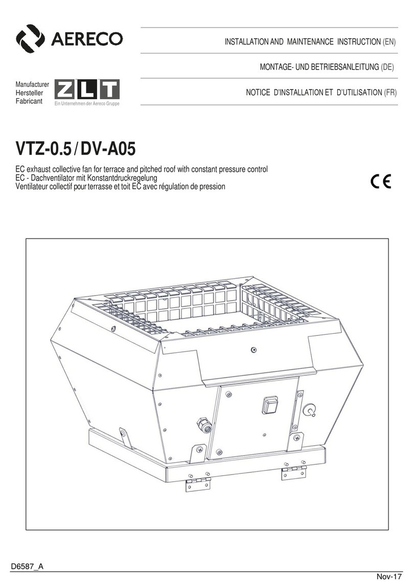
Aereco VCZ Series Technical specifications

Aereco

Aereco VCZ Series Technical specifications

Aereco DXR Installation instructions

Aereco

Aereco DXR Installation instructions

Aereco V4A Premium User manual

Aereco

Aereco V4A Premium User manual

Aereco V2A User manual

Aereco

Aereco V2A User manual

Aereco V4A User manual

Aereco

Aereco V4A User manual

Aereco ZLT VTZ Series Installation instructions

Aereco

Aereco ZLT VTZ Series Installation instructions

Aereco VCZ 0 Smart Operating and maintenance instructions

Aereco

Aereco VCZ 0 Smart Operating and maintenance instructions

Aereco V4A Premium User manual

Aereco

Aereco V4A Premium User manual

Aereco VPH2 User manual

Aereco

Aereco VPH2 User manual

Aereco HAT-HD Operator's manual

Aereco

Aereco HAT-HD Operator's manual

Aereco V2A User manual

Aereco

Aereco V2A User manual

Aereco CONNECT WP120 User manual

Aereco

Aereco CONNECT WP120 User manual

Aereco VCZ Series Installation instructions

Aereco

Aereco VCZ Series Installation instructions

Aereco V2A User manual

Aereco

Aereco V2A User manual

Aereco VAM User manual

Aereco

Aereco VAM User manual

Aereco V5S User manual

Aereco

Aereco V5S User manual

Aereco VMX Series User manual

Aereco

Aereco VMX Series User manual

Aereco VBP+ Instruction Manual

Aereco

Aereco VBP+ Instruction Manual

Aereco VBP+ R Instruction Manual

Aereco

Aereco VBP+ R Instruction Manual

Aereco VAM VES 250 User manual

Aereco

Aereco VAM VES 250 User manual

Aereco VTZ-0.5 Operating and maintenance instructions

Aereco

Aereco VTZ-0.5 Operating and maintenance instructions

Aereco ZLT VTZ Series Technical specifications

Aereco

Aereco ZLT VTZ Series Technical specifications

Aereco V4A User manual

Aereco

Aereco V4A User manual

Aereco ZLT AWN DV Basic 101 Technical specifications

Aereco

Aereco ZLT AWN DV Basic 101 Technical specifications

Popular Fan manuals by other brands

NSB FAN TEEGA instruction manual

NSB FAN

NSB FAN TEEGA instruction manual

Kichler Lighting Kevlar 310150WCP instruction manual

Kichler Lighting

Kichler Lighting Kevlar 310150WCP instruction manual

TJERNLUND Duct Booster RB10 Owner's instructions

TJERNLUND

TJERNLUND Duct Booster RB10 Owner's instructions

Fakir VC 20 S operating instructions

Fakir

Fakir VC 20 S operating instructions

Bimar VP42T Instruction booklet

Bimar

Bimar VP42T Instruction booklet

LUCCI Air Altitude Eco Led Installation instructions manual

LUCCI Air

LUCCI Air Altitude Eco Led Installation instructions manual

Delta Electronics GFB0812DHU Dimensions and installation information

Delta Electronics

Delta Electronics GFB0812DHU Dimensions and installation information

Eberg AIRO 35 instruction manual

Eberg

Eberg AIRO 35 instruction manual

Westinghouse ETL-ES-Petite-WH16 owner's manual

Westinghouse

Westinghouse ETL-ES-Petite-WH16 owner's manual

Saturn ST-FN8265 quick start guide

Saturn

Saturn ST-FN8265 quick start guide

Skov BF 50 Technical user guide

Skov

Skov BF 50 Technical user guide

Addvent AVIMI100 user manual

Addvent

Addvent AVIMI100 user manual

Trotec TTW-25000S operating manual

Trotec

Trotec TTW-25000S operating manual

Faro Barcelona andros manual

Faro Barcelona

Faro Barcelona andros manual

S&P TTT Series manual

S&P

S&P TTT Series manual

KHIND SF 1625 instruction manual

KHIND

KHIND SF 1625 instruction manual

Harbor Breeze 52 IN CLASSIC STYLE 40081 installation guide

Harbor Breeze

Harbor Breeze 52 IN CLASSIC STYLE 40081 installation guide

Dräger Oxylog Instructions for use

Dräger

Dräger Oxylog Instructions for use

manuals.online logo
manuals.online logoBrands
  • About & Mission
  • Contact us
  • Privacy Policy
  • Terms and Conditions

Copyright 2025 Manuals.Online. All Rights Reserved.