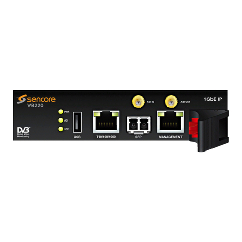
AERF WIRELESSBAND 2.F User manual

Instruction Manual
( WIRELESSBAND 2.F)
1. GENERAL
2. TRANSMITTER AND RECEIVER TERMINAL CONNECTIONS
3. TYPICAL CONFIGURATION FOR Optical Low Power Safety Edge (TRANSMITTER)
1 2 3 4 5 6
INPUT 1 COM 1
INHIBITOR
COM 2 INPUT 2 VCC
1 2 3 4 5 6 7 8 9 10 11 12
VCC1 OUTPUT 1
VCC2 OUTPUT 2 TEST
RELAY 1
TEST RELAY 2 /
INHIBITOR
+/~-/~
12/24V
AC/DC
TRANSMITTER
RECEIVER
1 2 3 4 5 6
INPUT 1 COM 1 Inhibitor COM 2 INPUT 2 VCC
GND / 0V
OUTPUT SIGNAL
Optical Low Power Safety Edge
WHITE
BROWN
GREEN
5 VDC
TRANSMITTER
GB
1 - 6
1234
ON
5
Optical sensor power
supply from receiver (ON)
Optical sensor power
supply from receiver (OFF)
Inhibition active
in receiver (ON)
Receiver options configuration
for Optical Safety Edge
123
ON +
See points 4.3 and 10.1 for
other transmitter connections.
4. CONFIGURATION TYPES FOR Optical Low Power Safety Edge INHIBITION
WARNING!!
Desired Transmitter and receiver options must be set before the transmitter code memorization, otherwise system will not
work correctly. If there is some doubt about configuration is recomended to do a memory reset.
Examples:
- If you want to use transmitter inhibitor TX OPTION 2 and RX OPTION 5 must be OFF before the transmitter code memorization.
If used an Optical Safety Edge, we recommend that use the inhibitor for
extend the batteries life. Otherwise, the estimated life is about 6 months.
If you want to use receiver inhibitor TX OPTION 2 and RX OPTION 5 must be ON before the transmitter code memorization.-
- Two channels wireless system communication, for the optical safety edge communication. For example, the pedestrian door contact to
controlunit.Thesystemhasa longbatterylife(morethan4years)workingwitha resistiveormechanicalsafetyedge.
Translation of the original instructions
1.1 SAFETY INSTRUCTIONS
-Reactiontime<60ms
-ARelaytestmustbedonebeforeanyoperationtofulfillEN13849-1Cat2PL-C.
- DevicewithSELV/PELVPowerSupply
(accordingTÜVtestreportAV86368TCertificatenºM6A141290800001)
TÜV Certificate nºM6A 14 12 90800 001
WIRELESSBAND 2.F
RoHS
06/02/15

1 2 3 4 5 6 7 8 9 10 11 12
VCC1 OUTPUT 1
VCC2 OUTPUT 2 TEST
RELAY 1 INHIBITOR
1 2 3 4 5 6 7 8 9 10 11 12
VCC1 OUTPUT 1
VCC2 OUTPUT 2 TEST
RELAY 1 INHIBITOR
1 2 3 4 5 6 7 8 9 10 11 12
VCC1 OUTPUT 1
VCC2 OUTPUT 2 TEST
RELAY 1 INHIBITOR
1 2 3 4 5 6 7 8 9 10 11 12
VCC1 OUTPUT 1
VCC2 OUTPUT 2 TEST
RELAY 1 INHIBITOR
+/~
+/~+/~
+/~
-/~
-/~-/~
-/~
11
22
44
55
ON ON
55
Control unit
N.O. AutoTest
Output
Control unit N.O.
Relay Output
Control unit
N.C. AutoTest
Output
Control unit N.C.
Relay Output
33
RECEIVER RECEIVER
4.1 INHIBITION FROM RECEIVER: CONTROL UNIT WITH AUTOTEST N.O. or N.C. OUTPUT
Common
Common
Test
Test
N.C.: Normally Closed
N.O.: Normally Open
GB
For the system will work
correctly, must have a
test signal before each
maneuver.
For the system will work
correctly, the relay signal
must be active during the
maneuvre.
2 - 6
AUTOTEST N.O. AUTOTEST N.C.
11
22
44
55
ON ON
55
33
RECEIVER TRANSMITTER
TRANSMITTER TRANSMITTER
TRANSMITTER
RECEIVER
1
11
1
2
22
2
3
33
3
ON
ON ON
ON
+
++
+
4.1.1 OSE POWER SUPPLY TIME PROGRAMMING PROCESS (only with OPTION 4 & 5 - ON)
PROG.
1.5s
PROG.
SAVE & QUIT
1 X
BEEP RELEASE
RECEIVER
PRESS
RECEIVER RECORD TIME*
LED ON
TRANSMITTERS
PROG. MODE
PROG.
1.5s
PRESS
RECEIVER
LED FLASHES
PROG. MODE
POWER SUPPLY
TIME
FLASH
PROG.
1.5s
PRESS
RECEIVER
PROG.
RELEASE
RECEIVER
PROG.
RELEASE
RECEIVER
Note: Default recorded time is 30 sec.
* Record the optical
safety edge power
supply time. (Equal
or more than door
operation time).
4.2 OPTICAL SAFETY EDGE INHIBITION FROM RECEIVER (USE POSITIONING CONTACT N.O. or N.C.)
Note: For the control panel TEST output, must program the optical safety edge power supply time
(equal or more than door maneuvre time)(follow point 4.1.1).
CONTACT N.O. CONTACT N.C.
WIRELESSBAND 2.F
RoHS
06/02/15

Inhibitor disabled in receiver and enabled in transmitter
1 2 3 4 5 6
INPUT 1 COM 1 Inhibitor COM 2 INPUT 2 VCC
Inhibition Input
GB
3 - 6
4.3 OPTICAL SAFETY EDGE INHIBITION FROM TRANSMITTER
1234
ON
5
Optical sensor power
supply from receiver (ON)
Optical sensor power
supply from receiver (OFF)
5. RECEIVER OUTPUTS CONNECTIONS
WITH BRIDGE SELECTOR
WITHOUT BRIDGE SELECTOR
LED ON - Security OK
LED OFF - Obstacle detected
6. RECEIVER LED INDICATOR
FLASH
8K2
8K2
3 4 5 6 7 8
6 7 8
3 4 5
*With power supply connected
and without safety failure.
7. MOUNTING
M
Safety Edge
Safety Edge
INDUSTRIAL SECTIONAL DOOR SLIDING DOOR
Motor
Motor
Wirelessband
Receiver
Wireless
Communication
Wireless
Communication
Wirelessband
Transmitter 1
Wirelessband
Transmitter
Wirelessband
Receiver
Wirelessband
Transmitter 2
M
9. START-UP
PROG.
TRANSMITTER
RECEIVER
>1m
+-
12/24V 0V
AC/DC
VCC1 VCC2
OPTICAL EDGE?
ONLY WITH
OPTION 4
ON
12/24V
ON
CONTROL
UNIT
220V
M
++
--
OK?
1. INSERT BATTERIES 2. CONNECT RECEIVER 3. CHECK SWITCH
SETTINGS 5. CARRY OUT
PROGRAMMING PROCESS
(SEE POINT 9.2)
7. MINIMUM DISTANCE
1 m. 8. INSTALL & WIRE
RECEIVER 9. TURN ON
POWER SUPPLY 10. TEST SAFETY EDGE
ON DOOR.
6. INSTALLAND WIRE
TRANSMITTER ON
DOOR
4. SAFETY EDGE TYPE
CONFIGURATION
(SEE POINT 10.2)
*BY DEFAULT IN KIT, THE
T R A N S M I T T E R I S
R E C O R D E D I N T O
RECEIVER.
WIRELESSBAND 2.F
RoHS
06/02/15

1 2 3 4 5 6
INPUT 1 COM 1 Inhibitor COM 2 INPUT 2 VCC
Input 2 Mechanical or Resistive (8K2)
Safety Edge
Safety Edge
(Mechanical or Resistive 8K2)
1234
ON
5
Mechanical (OFF)
Resistive (ON)
Transmitter and receiver options configuration
for Mechanical or Resistive Safety Edge
123
ON
GB
++
(see point 10.2)
4 - 6
Optical sensor power
supply from receiver (ON)
Optical sensor power
supply from receiver (OFF)
9. PROGRAMMING PROCESS
TRANSMITTER MANUAL PROGRAMMING (up to 7 transmitters per receiver)
PROG.
1.5s
PROG. 10s
SAVE & QUIT
2 X BEEPS
1 X
BEEP
1 X
BEEP RELEASE
RECEIVER
PRESS
RECEIVER PRESS
TRANSMITTER WAIT
MEMORY RESET
PROG. 10s
PROG. PROG.
1.5s 3s
SAVE & QUIT
2 X BEEPS
WAIT
RELEASE
RECEIVER
1 X
BEEP # BEEPS
PRESS
RECEIVER KEEP IT
PRESSED
MEMORY FULL INDICATOR
In case of full memory you will hear several acoustic signals for 10 seconds upon trying to memorize a new transmitter.
The system can store 7 transmitters per channel.
LOW BATTERY INDICATOR
Low battery indication consists on 4 acoustic sounds each time a message is received from a programmed transmitter. Both, warning LED and
buzzer are set on simultaneously.
10. OTHER CONFIGURATIONS
10.1 TRANSMITTER
1 2 3 4 5 6
INPUT 1 COM 1 Inhibitor COM 2 INPUT 2 VCC Safety Edge (Mechanical or Resistive 8K2)*
*Choose the Safety Edge type
with transmitter option 1
Resistive
Mechanical
123
ON
Input 1 Safety Edge (Mechanical or Resistive 8K2)
WIRELESSBAND 2.F
RoHS
06/02/15

GB
10.2 Input 2 LOW POWER OPTICAL SAFETY EDGE or RESISTIVE PROGRAMMING PROCESS
3. STATUS INDICATION 4. PRESS TRANSMITTER
PROG. BUTTON FOR
CHANGE STATUS
5. STATUS CHANGE
1. CONNECT OPTICAL
EDGE TO TRANSMITTER
4 5 6
COM2 VCC1
IN2
FLASH
2X
OPTICAL
RESISTIVE/
MECHANICAL
5X FLASH PROG.
1.5s OPTICAL
RESISTIVE /
MECHANICAL
6. LED FLASH 7. SAVE & EXIT
FLASH
NOTE: Default optical configuration.
You have 5 seconds after launch to make the change of safety edge status.
2. CONNECT BATTERIES
++
--
5 - 6
6. OTHER CONFIGURATIONS (Receiver)
11
22
44
55
ON ON
55
33
RECEIVER RECEIVER
Note: Configurations for Mechanical or Resistive Safety Edge
1 2 3 4 5 6 7 8 9 10 11 12
VCC1 OUTPUT 1
VCC2 OUTPUT 2 TEST
RELAY TEST
RELAY 2
1 2 3 4 5 6 7 8 9 10 11 12
VCC1 OUTPUT 1
VCC2 OUTPUT 2 TEST
RELAY 1 TEST
RELAY 2
+/~+/~
-/~-/~
Common
Common
Test
Test
N.C.: Normally Closed
N.O.: Normally Open
CONFIGURATION WITH CONTROL UNIT TEST N.O. or N.C. OUTPUT
Control unit N.O.
Test Output Control unit N.O.
Test Output
11. RECEIVER OPTION SELECTOR
1234
ON
1234
ON
1234
ON
1234
ON
1234
ON
1234
ON
1234
ON
1234
ON
TRANSMITTER
FREQUENCY*
INHIBITION
TYPE
RELAY TEST/
INHIBITOR
TYPE
CLASS 2 Enabled (Conforms UNE-
EN 13849-2)
Disabled (Stock configuration)
Normally Closed Contact
Normally Open Contact
Inhibition by autotest contact.**
Inhibition by positioning
contact.
869,85 MHz
868,95 Mhz
5
5
5
5
5
5
5
5
1234
ON
1234
ON
INHIBITION
BY Receiver.
Transmitter.
5
5
ATTENTION:
*Receiver configuration MUST be the same that transmitter
configuration.
**With Option 4 ON, you must program the Optical Safety
Edge power supply time (equal or more than the door
operatingtime),followingpoint4.1.1.
WIRELESSBAND 2.F
RoHS
06/02/15

- Installation, start-up, modification and retrofitting of
thesystemmayonlybecarriedoutbyaqualifiedperson.
-Switchoff theoperating voltagebeforeworkingonthesystem.
- The system doesn’t have fuse protection. Is
recommended include exterior protection minimum
100mAandmaximum250mA.
WARNING!!
GB
Receiver supply voltage 12/24 AC/DC
Transmitter supply voltage 2x AA lithium battery 3.6V
Transmitter inputs Selectable by dip-switch and prog.
1 Resistive / contact /optical
1 Resistive / contact
Transmitter Inhibition input type Power free contact
Receiver memory 7 transmitters per channel
Receiver Output 2 Relay, micro disconnection 1B
Receiver test inputs
Type
Receiver Power consumption
Ball pressure test (IEC 695-10-2) PCB (125ºC) WRAP (75ºC)
Pollution degree 2
Protection class (IEC 60529) Ip55
Frequency Channels
Range
Working temperature
Software
Rated transient over voltage
Transmitter power consumption
Maximum screw force
Machine Security Normative
Reaction time
or power free contact
2
- 12/24V AC/DC , contact, open collect.
0.5 W - 12 V / 1,2 W - 24 V
868.95MHz & 869.85MHz
100m
-20ºC to +55ºC
Class A
330V
Transmitting 17mA / stand by 16uA
0,4 Ncm Category 2, with TEST13849-2008 PL-C
60 ms
(according TÜV test report AV86368T
Certificate nº M6A 14 12 90800 001)
TECHNICAL SPECIFICATIONS
CEDECLARATION OFCONFORMITY
Aplicaciones electrónicas y de Radiofrecuencia S.L Pol. Sot dels Pradals C/ Sot dels pradals, 4
08500Vic(Barcelona)B61840732DECLARES,underherownresponsibilitythatproductcomplies
with the requirements of the R&TTE 99/05/CE European parliament directive of March 9th 1999.
This directive was transposed to the Spanish legislation by means of Real Decree 1890/2000 in
November20thof2000.Formoreinformation visitthewebsitewww.aerf.eu
6 - 6
12. TRANSMITTER OPTIONS SELECTOR
SAFETY EDGE
TYPE (INPUT 2)
TRANSMITTER
FREQUENCY
IN 1 SAFETY
EDGE TYPE
Optical sensor power
supply from receiver (ON)
1
1
2
2
3
3
4
4
ON
ON
5
5
FLASH
FLASH
5X
2X
(see point 10.2)
IN2 - Resistive
Safety Edge
IN2 - Optical
Safety Edge
(default)
(see point 10.2)
Input 2 Resistive
Input 2 Optical
Inhibition in Receiver
and Transmitter
Input 2 Mechanical
Not used
123
ON
123
ON
1
1
1
2
2
2
3
3
3
ON
ON
ON
1
1
1
2
2
2
3
3
3
ON
ON
ON
123
ON
ON
Resistive (8k2 )
Mechanical (0Ω)
Ω
869,85 Mhz (setting MUST
match that of receiver)
868,95 Mhz (setting MUST
match that of receiver)
+
+
+
+
RECEIVER TRANSMITTER
TRANSMITTER
RECEIVER
Optical sensor power
supply from receiver (OFF)
Resistive
configuration
Optical
configuration
WIRELESSBAND 2.F
RoHS
06/02/15
Table of contents
