manuals.online logo
Brands
  1. Home
  2. •
  3. Brands
  4. •
  5. PaloAlto Networks
  6. •
  7. Network Hardware
  8. •
  9. PaloAlto Networks PA-455 User manual

PaloAlto Networks PA-455 User manual

PA-455
docs.paloaltonetworks.com
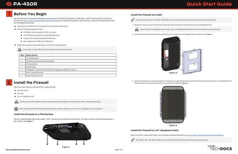
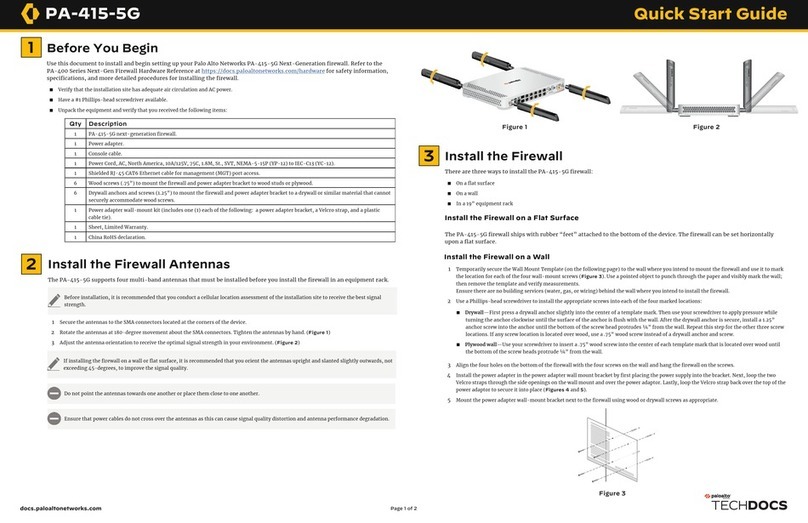
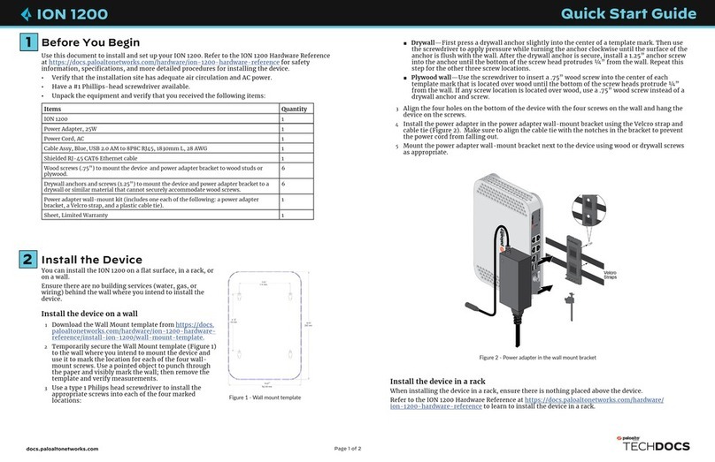
1Before You Begin
Use this document to install and begin setting up your Palo Alto Networks PA-455 Next-Generation firewall. Refer to the PA-
400 Series Next-Gen Firewall Hardware Reference at https://docs.paloaltonetworks.com/hardware for safety information,
specifications, and more detailed procedures for installing the firewall.
◼Verify that the installation site has adequate air circulation and AC power.
◼Have a #1 Phillips-head screwdriver available.
◼Unpack the equipment and verify that you received the following items:
Page 1 of 4
Quick Start Guide
Qty Description
1PA-455 next-generation firewall.
1Power adapter.
1Console cable.
1Power Cord, AC, North America, 10A/125V, 75C, 1.8M, St., SVT, NEMA-5-15P (YP-12) to IEC-C13 (YC-12).
1Shielded RJ-45 CAT6 Ethernet cable for management (MGT) port access.
6Wood screws (.75”) to mount the firewall and power adapter bracket to wood studs or plywood.
6Drywall anchors and screws (1.25”) to mount the firewall and power adapter bracket to a drywall or similar material that cannot
securely accommodate wood screws.
1Power adapter wall-mount kit (includes one (1) each of the following: a power adapter bracket, a Velcro strap, and a plastic
cable tie).
1Sheet, Limited Warranty.
1China RoHS declaration.
Install the Firewall
There are three ways to install the PA-455 firewall:
◼On a flat surface
◼On a wall
◼In a 19” equipment rack
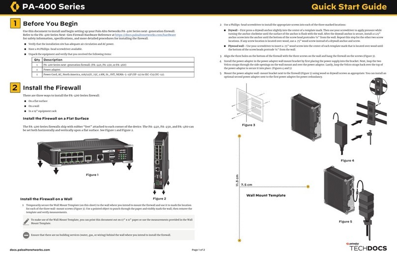
Install the Firewall on a Flat Surface
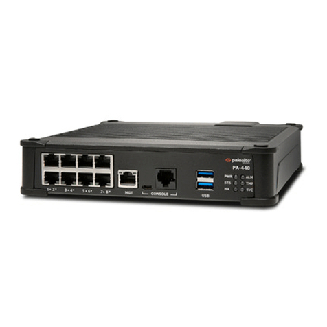
The PA-455 firewall ships with rubber “feet” attached to the bottom of the device. The firewall can be set horizontally upon a
flat surface. (Figure 1)
2
Figure 1
Install the Firewall on a Wall
1 Temporarily secure the Wall Mount Template (on the following page) to the wall where you intend to mount the firewall and use it to mark the
location for each of the four wall-mount screws (Figure 2). Use a pointed object to punch through the paper and visibly mark the wall; then remove
the template and verify measurements. Ensure there are no building services (water, gas, or wiring) behind the wall where you intend to install the
firewall.
2 Attach the firewall to the wall mount using three #6-32 screws. (Figures 3 and 4)
3 Atach the wall mount to the four marked holes in the wall using the appropriate screws for your wall type:
◼Drywall—First press a drywall anchor slightly into the center of a template mark. Then use your screwdriver to apply pressure while turning the
anchor clockwise until the surface of the anchor is flush with the wall. After the drywall anchor is secure, install a 1.25” anchor screw into the
anchor until the bottom of the screw head protrudes ¼” from the wall. Repeat this step for the other three screw locations. If any screw location is
located over wood, use a .75” wood screw instead of a drywall anchor and screw.
◼Plywood wall—Use your screwdriver to insert a .75” wood screw into the center of each template mark that is located over wood until the bottom of
the screw heads protrude ¼” from the wall.
4 Install the power adapter in the power adapter wall-mount bracket using the Velcro straps and cable tie. Make sure to align the cable tie with the
notches in the bracket to prevent the power cord from falling out. Next, loop the two Velcro straps through the side openings on the wall mount and
over the power adapter. Lastly, loop the Velcro straps back over the top of the power adapter to secure it into place. (Figure 5)
5 Mount the power adapter wall-mount bracket next to the firewall using wood or drywall screws as appropriate. You can install an optional second
power adapter next to the first power adapter for power redundancy.
Figure 4
Figure 3
Figure 2
Figure 5
PA-455 QUICK START GUIDE (CONTINUED)
docs.paloaltonetworks.com Page 2 of 4
Wall Mount Template
PA-455 QUICK START GUIDE (CONTINUED)
docs.paloaltonetworks.com Page 3 of 4
Figure 6
Install the Firewall in a 19” Equipment Rack
The rack kit (PAN-1RU-RGD-RACK-KIT-4POST) is not included with the firewall and must be purchased separately.
The mounting equipment takes up 1RU of space. One rack kit holds a single PA-455.
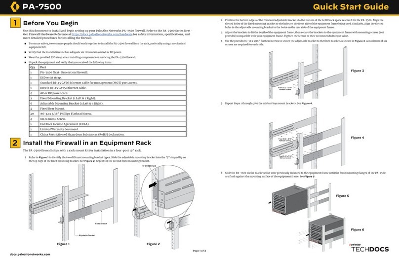
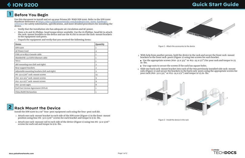
1 Slide one of the adjustable mounting brackets into one of the fixed mounting brackets to create a mounting rail. Repeat for the second
mounting rail. The adjustable and fixed brackets are the same for the left and right side. (Figure 6)
2 Align the bottom edge of the mounting rails to the bottom of the 1 RU reserved for your firewall. Align the slotted holes in the adjustable
mounting bracket to the holes on the rear of the equipment frame.
3 Secure the rails to the equipment frame with mounting screws (not provided) compatible with your equipment frame. Tighten the screws to
their recommended torque value. (Figure 7)
4 With the front of the firewall facing forward, align the four rubber feet on the bottom of the device to the slotted holes in the provided
mounting tray. (Figure 8)
5 While holding the firewall, carefully flip the mounting tray over to reveal its underside.
6 Secure the firewall in place using three of the provided #6-32 x 3/16” Long Flathead screws. (Figure 8)
7 Flip the mounting tray back into an upright position.
8 Slide the firewall power supply into the marked position. Fasten the provided velcro strap around the power supply until it is secure in place.
(Figure 9)
9 Plug the power supply connector into the front of the firewall. Using the provided tie-wraps, bind and secure the power supply cable to the
metal hooks in the mounting tray. (Figure 10)
10 Slide the mounting tray into the rails previously fixed to the equipment rack. Stop when the front flange on the mounting tray is flush with the
front of the rail.
11 Align the slotted holes in the mounting tray to the holes in the equipment frame. Secure the mounting tray to the equipment frame on both
sides using 3 screws each (not provided). The screws must be compatible with your equipment frame. (Figure 11 — Different model pictured)
Figure 7
Figure 8
Use the provided bracket on the mounting tray to keep the power adapter cable in place.
Figure 9
Figure 10 Figure 11
PA-455 QUICK START GUIDE (CONTINUED)
docs.paloaltonetworks.com | © 2023 | Palo Alto Networks, Inc.
4Connect to the Management Interface
Page 4 of 4
Where To Go Next
To learn more about the firewall, refer to the PA-400 Series Next-Gen Firewall Hardware Reference Guide:
https://docs.paloaltonetworks.com/hardware.
To learn how to configure Palo Alto Networks firewalls, go to the Technical Documentation portal:
https://docs.paloaltonetworks.com.
(Use the Getting Started information in the PAN-OS Administrator’s Guide for initial configuration tasks.)
Start here to Register and Set Up your firewall and access all resources and support tools:
https://go.paloaltonetworks.com/CustomerLaunchPad
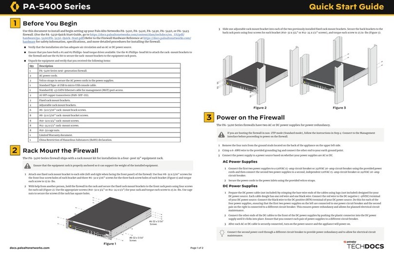
Power On the Firewall
1 Connect the DC connector from the power adapter into one of the power adapter ports on the firewall and tighten the thumb screw to secure
the cable to the firewall (Figure 12).
2 Plug the AC connector from the power adapter into your AC power source. After power is connected, the firewall powers on as indicated by the
green power LED on the front of the device. The LED shows green when a functioning power adapter is connected.
3 (Optional) Repeat Steps 1 and 2 for a second power adapter. The PA-455 can use an optional second power adapter for redundancy.
Connect in ZTP Mode
1 Unbox the firewall.
2 Connect the ZTP port (Ethernet port 1) on the firewall to an active network switch.
3 Power on the firewall.
4 Follow the instructions provided by your Panorama administrator to register your ZTP firewall. You will have to enter the serial number
(12-digit number identified as S/N) and claim key (8-digit number). These numbers are on stickers attached to the back of the device.
5 Contact your Panorama administrator if you require further assistance.
Figure 12
If you are booting the firewall in non-ZTP mode (Standard mode), follow the instructions in Step 5 before proceeding to power on the
firewall.
Connect in Standard Mode (Via Web Interface)
1 Connect the standard RJ-45 Ethernet cable from the RJ-45 port on your computer to the MGT port on the firewall.
2 Change the IP address on your computer to an address in the 192.168.1.0/24 network, such as 192.168.1.2.
3 Power on the firewall.
4 From a web browser, go to https://192.168.1.1.
5 On the firewall login screen, a prompt will ask if you wish to continue booting in ZTP mode or if you would like to switch to standard
mode. Select Standard Mode and the firewall will begin rebooting in standard mode.
Connect in Standard Mode (Via CLI)
1 Connect the standard RJ-45 Ethernet cable from the RJ-45 port on your computer to the MGT port on the firewall.
2 Ensure that you have access to a terminal emulator such as PuTTY.
3 Change the IP address on your computer to an address in the 192.168.1.0/24 network, such as 192.168.1.2.
4 Power on the firewall.
5 Access the firewall CLI using your terminal emulator. Watch for the following prompt:
Do you want to exit ZTP mode and configure your firewall in standard mode (yes/no)[no]?
Enter “yes.” The system will then ask you to confirm. Enter “yes” again to boot the firewall in standard mode
6 Stand by for approximately 5 minutes as the firewall boots up.
7 From a web browser, go to https://192.168.1.1.
8 When prompted, log in to the web interface using the default username and password (admin/admin).
3

Other PaloAlto Networks Network Hardware manuals

PaloAlto Networks PA-5400 Series User manual

PaloAlto Networks

PaloAlto Networks PA-5400 Series User manual

PaloAlto Networks PA-7500 User manual

PaloAlto Networks

PaloAlto Networks PA-7500 User manual

PaloAlto Networks ION 1200-C-NA/ROW User manual

PaloAlto Networks

PaloAlto Networks ION 1200-C-NA/ROW User manual

PaloAlto Networks PA-5400 Series User manual

PaloAlto Networks

PaloAlto Networks PA-5400 Series User manual

PaloAlto Networks ION 9200 User manual

PaloAlto Networks

PaloAlto Networks ION 9200 User manual

PaloAlto Networks PA-400 Series User manual

PaloAlto Networks

PaloAlto Networks PA-400 Series User manual

PaloAlto Networks PA-7500 Application guide

PaloAlto Networks

PaloAlto Networks PA-7500 Application guide

PaloAlto Networks PA-400 Series Application guide

PaloAlto Networks

PaloAlto Networks PA-400 Series Application guide

PaloAlto Networks M-200 User manual

PaloAlto Networks

PaloAlto Networks M-200 User manual

PaloAlto Networks M-500 User manual

PaloAlto Networks

PaloAlto Networks M-500 User manual

PaloAlto Networks ION 1200-S Application guide

PaloAlto Networks

PaloAlto Networks ION 1200-S Application guide

PaloAlto Networks ION 3200 User manual

PaloAlto Networks

PaloAlto Networks ION 3200 User manual

PaloAlto Networks ION 9200 Application guide

PaloAlto Networks

PaloAlto Networks ION 9200 Application guide

PaloAlto Networks ION 1200-C-5G-WW User manual

PaloAlto Networks

PaloAlto Networks ION 1200-C-5G-WW User manual

PaloAlto Networks M-200 Application guide

PaloAlto Networks

PaloAlto Networks M-200 Application guide

PaloAlto Networks PA-400 Series User manual

PaloAlto Networks

PaloAlto Networks PA-400 Series User manual

PaloAlto Networks ION 1000 Application guide

PaloAlto Networks

PaloAlto Networks ION 1000 Application guide

PaloAlto Networks PA-400R Series Application guide

PaloAlto Networks

PaloAlto Networks PA-400R Series Application guide

PaloAlto Networks WF-500-B Application guide

PaloAlto Networks

PaloAlto Networks WF-500-B Application guide

PaloAlto Networks TECHDOCS ION 1200 User manual

PaloAlto Networks

PaloAlto Networks TECHDOCS ION 1200 User manual

PaloAlto Networks PA-5420 User manual

PaloAlto Networks

PaloAlto Networks PA-5420 User manual

PaloAlto Networks PA-450R User manual

PaloAlto Networks

PaloAlto Networks PA-450R User manual

PaloAlto Networks ION 3200 Application guide

PaloAlto Networks

PaloAlto Networks ION 3200 Application guide

PaloAlto Networks ION 5200 Application guide

PaloAlto Networks

PaloAlto Networks ION 5200 Application guide

Popular Network Hardware manuals by other brands

Enterasys 8000/8600 Getting started guide

Enterasys

Enterasys 8000/8600 Getting started guide

Allied Telesis AT-AR040 Hardware reference

Allied Telesis

Allied Telesis AT-AR040 Hardware reference

ZyXEL Communications ATP Series manual

ZyXEL Communications

ZyXEL Communications ATP Series manual

FATEK FBs-CBES Series manual

FATEK

FATEK FBs-CBES Series manual

Allied Telesis AT-XEM-12S installation guide

Allied Telesis

Allied Telesis AT-XEM-12S installation guide

Top Global MobileBridge MB8000 user guide

Top Global

Top Global MobileBridge MB8000 user guide

ADTRAN 1442390G1 manual

ADTRAN

ADTRAN 1442390G1 manual

Uniden Pro7804N1 user manual

Uniden

Uniden Pro7804N1 user manual

Foxconn RAID 91-187-C51-G0-0E user guide

Foxconn

Foxconn RAID 91-187-C51-G0-0E user guide

ADTRAN 414 RG manual

ADTRAN

ADTRAN 414 RG manual

Nortel BCN Product support bulletin

Nortel

Nortel BCN Product support bulletin

Panasonic PN261693D manual

Panasonic

Panasonic PN261693D manual

Security Camera King NVR-ELC-16 user manual

Security Camera King

Security Camera King NVR-ELC-16 user manual

Cisco ONS 15216-MD-40-ODD install guide

Cisco

Cisco ONS 15216-MD-40-ODD install guide

Altronix TROVE T2SSK78 installation guide

Altronix

Altronix TROVE T2SSK78 installation guide

Imcon International Internet Backpack quick start guide

Imcon International

Imcon International Internet Backpack quick start guide

Altronix NetWay V Series installation guide

Altronix

Altronix NetWay V Series installation guide

Samsung SNR-6400 user manual

Samsung

Samsung SNR-6400 user manual

manuals.online logo
manuals.online logoBrands
  • About & Mission
  • Contact us
  • Privacy Policy
  • Terms and Conditions

Copyright 2025 Manuals.Online. All Rights Reserved.