AERMEC ANR R407C User manual

TECHNICAL MANUAL
ANR
R407C
R407C
Air cooled heat pumps with high-efficiency scroll compressors
IANRTZ. 0807. 6343710_00
English
12 kW ÷ 18 kW
❄14 kW ÷ 21 kW
❊
MANUAL TÉCNICO
Bombas de calor condensadas por aire con compresores scroll de alta eficiencia
Español

Dear Customer,
Thank you for choosing AERMEC. It is the result of long experience and design-specific research.The article has been made
of materials of the highest quality and incorporates cutting edge technology.
In addition, all our products bear the EC mark indicating that they meet the requirements of the European Machine
Directive regarding safety. The standard of quality is permanently being monitored and AERMEC products are therefore a
synonym for Safety, Quality and Reliability.
The data might undergo modifications considered necessary for the improvement of the product at any time, without the
obligation for any notice thereof.
Thank you again.
AERMEC S.p.A

Declaration of conformity ......................................................... 4
1. General standards............................................................5
2. Description and choice of unit.....................................6
2.1 Available versions ..................................................................6
2.1.1 Standard equipment ............................................................6
2.2 Configurator .............................................................................7
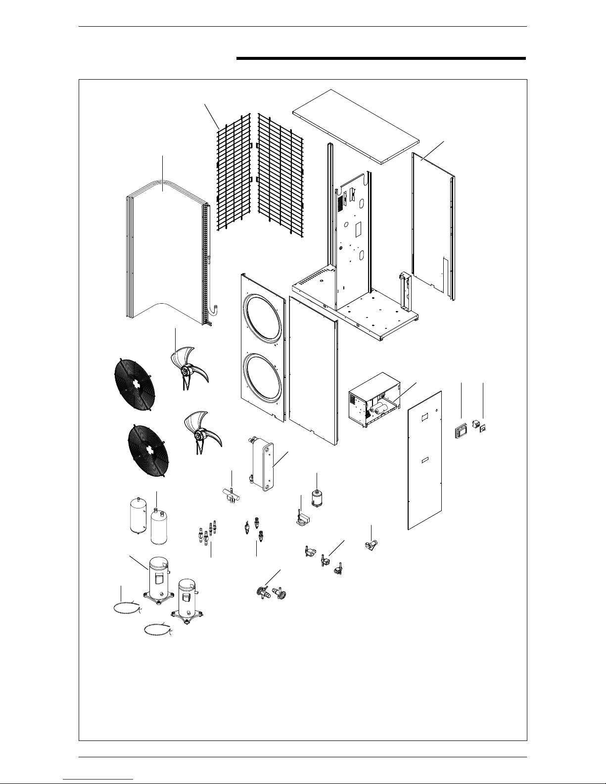
3 Description of components 8
3.1 Standard ANR version (H)..................................................8
3.2 ANR version with accumulation (HA) ............................9
3.3 ANR version with accumulation
and secondary heater (HK).............................................10
3.4 Cooling circuit.........................................................................11
4 Standard equipment 13
4.1 Chiller circuit..........................................................................13
4.2 Frame and fans ...................................................................13
4.3 Hydraulic components .....................................................13
4.4 Safety and control components....................................13
4.5 Electrical components...................................................... 13
4.6 Modu Control electronic adjustment..........................14
5 Accessories......................................................................14
5.1 Table of compatible accessories...................................14
6 Technical data.................................................................. 15
6Standard versions 230V .................................................15
6.1 Versions with accumulation 230V .............................16
6.2 Standard version 400V.....................................................17
6.3 Version with accumulation 400V ................................18
7 Selection criteria............................................................19
7.1 Design data............................................................................19
8 Corrective co-efficients ...............................................20
8.1 ANR502 (HM) ..................................................................... 20
8.2 ANR802 (HM) ..................................................................... 20
8.3 ANR902 (HM) ...................................................................... 21
8.4 ANR502 (HPM-HAM-HKM)............................................ 21
8.5 ANR802 (HPM-HAM-HKM)............................................22
8.6 ANR902 (HPM-HAM-HKM)............................................22
8.7 ANR502 (H)...........................................................................23
8.8 ANR802 (H)...........................................................................23
8.9 ANR902 (H)...........................................................................24
8.10 ANR502 (HP-HA-HK).........................................................24
8.11 ANR802 (HP-HA-HK).........................................................25
8.12 ANR902 (HP-HA-HK).........................................................25
Cooling mode:
8.13 ANR502 (HM)......................................................................26
8.14 ANR802 (HM)......................................................................26
8.15 ANR902 (HM) ...................................................................... 27
8.16 ANR502 (HPM-HAM-HKM)............................................ 27
8.17 ANR802 (HPM-HAM-HKM)............................................28
8.18 ANR902 (HPM-HAM-HKM)............................................28
8.19 ANR502 (H) ......................................................................... 29
8.8 ANR802 (H).......................................................................... 29
8.9 ANR902 (H).......................................................................... 30
8.10 ANR502 (HP-HA-HK)........................................................ 30
8.11 ANR802 (HP-HA-HK)......................................................... 31
8.12 ANR902 (HP-HA-HK)......................................................... 31
9 Ethylene glycol solution ..............................................32
10 Pressure drops...............................................................34
10.1 Useful head.......................................................................34
11 Accumulation...................................................................35
11.1 Minimum/maximum system water
content ...............................................................................35
11. 2 Minimum water content recommended, for
versions without hydronic kit..........................................35
11.3 Maximum water content recommended ................35
11.4 Expansion tank calibration...............................................35
12 Sound data........................................................................36
13 Check and safety parameters setting...................36
13.1 Fan magnetothermals ......................................................36
13.2 Compressor magnetothermals....................................36
13.3 Pressure switch and transducer
thermomagnetic switches.............................................36
14 Versions with electric heater.................................... 37
15 Control logic for the compensation setpoint..... 37
16 Dimensions.......................................................................38
16.1 Minimum technical clearances ....................................38
16.2 ANR 0502-0802-0902...................................................38
To install the unit, please observe the safety warnings included in these instructions
Danger: high temperature
Danger: moving parts
Danger: power supply i
Danger: cut off power supply
General danger
Useful information and warnings

4
AERMEC S.P.A.
I-37040 Bevilacqua (VR) Italy – Via Roma, 44
Tel. (+39) 0442 633111
Fax 0442 93730 – (+39) 0442 93566
www .aermec.com - info @aermec .com
SERIAL NUMBER
DECLARATION OF CONFORMITY EC We, the undersigned, declare on our own exclusive responsibility that the object in
question, so defined:
NAME ANR
TYPE CHILLER HEAT PUMP
MODEL
To which this declaration refers, it complies with the following standardised regulations:
CEI EN 60335-2-40 Safety regulation regarding electric heat pumps, air conditioners and dehumidifiers
CEI EN 61000-6-1
CEI EN 61000-6-3 Electromagnetic immunity and emission in residential environment
CEI EN 61000-6-2
CEI EN 61000-6-4 Electromagnetic immunity and emission in industrial environment
EN378 Refrigerating system and heat pumps - Safety and environmental requirements
UNI EN 12735
UNI EN 14276
Round welding-free copper pipes for air conditioning and cooling
Pressure equipment for refrigerating systems and heat pumps
Thus meeting the essential requisites of the following directives:
- LV Directive: 2006/95/EC
- Electromagnetic Compatibility Directive 2004/108/EC
- Machine Directive 98/37/EC
- PED Directive relating to pressure equipment 97/23/EC
In compliance with Directive 97/23/EC, the product meets the Total Quality Warranty procedure (module H) with certificate no.
06/270-QT3664 Rev.3 issued by the notified body no. 1131 CEC via Pisacane 46 Legnano (MI) - Italy
Bevilacqua 15/01/2008
Marketing Director
Signature
ANR

5
1 GENERAL STANDARDS
1.1 Technical card
• This manual and the wiring diagrams
supplied with the unit must be kept
in a dry place for possible future con-
sultation and for the entire life of the
machine.
• Be careful to adhere to the instruc-
tions in this manual and observe the
safety regulations currently in place.
• The device must be installed in com-
pliance with the local legislation
currently in force in the country of
destination.
• Non-authorised tampering with the
equipment, whether electrical or me-
chanical, will make THE WARRANTY
VOID and exclude any liability on the
part of the company.
• Check the electrical characteristi-
cs shown on the registration plate
(fig.1.1) before making the electrical
wirings. Read the instructions in the
specific section about electrical wi-
rings.
• If the unit needs to be repaired, in all
cases contact a specialised AERMEC
aftersales centre and only use OEM
spare parts.
• The manufacturer furthermore decli-
nes any liability for any injury to per-
sons or damage to things resulting
from the failure to comply with the
information in this manual.
Any use other than that permitted or
outside the operating limits men-
tioned in this manual is forbidden if
not previously agreed with the com-
pany.
The warranty does not include pay-
ment for damage due to wrong in-
stallation of the unit by the installer.
• The warranty does not include pay-
ment for damage due to the impro-
per use of the unit by the user.
• The manufacturer does not consider
itself liable for accidents to the user
or the installer due to the incorrect
installation or improper use of the
unit.
•The device must be installed in such a
way that maintenance and/or repair
operations can be carried out. The
warranty of the device does not in
any case cover costs incurred as a re-
sult of motorised ladders, scaffolding
or any other lifting systems made
necessary to carry out the operations
under warranty.
The warranty is not valid when:
•theservices and the repairs havebeen
carried out by non-authorised per-
sonnel or companies;
• the unit has been repaired or modi-
fied in the past with non OEM spare
parts;
• the unit has not been adequately
maintained;
• if the instructions described in this
manual have not been followed;
• if non-authorised modifications have
been made.
N.B.:
The Manufacturer reserves the right
at all times to make any modification
for the improvement of its product
and is not obliged to add these mo-
dification to machines of previous
manufacture that have already been
delivered or are being built.
The warranty conditions are any
subject to the general sales condi-
tions at the moment the contract is
finalised.
Fig. 1
technical
card
NOTE:
If the identification plate is tampered
with, or removed, this prevents the
certain identification of the product,
making all installation and maintenance
operations more difficult.

6
2 DESCRIPTION AND CHOICE OF UNIT
2.1.1 STANDARD EQUIPMENT
The air cooled heat pumps of the ANR
series have been designed and manu-
factured to meet cooling/ heating re-
quirements and they are fit (except for
versions with incorporated accumula-
tion) for domestic hot water production
(DHW).
Machines are optimised for the heat
pump operation, by using the specific
high efficiency scroll compressor which
continues working until the outside air
temperature reaches -15 °C.
Use the chiller circuit to switch from
summer to winter use. Available in 3
sizes, the units are distinguished by an
extremely quiet operation and by a high
level of efficiency and reliability thanks
to the adoption of heat exchangers with
larger exchange surface and high per-
formance low noise scroll compressors.
Different versions are available so that a
great many different systems solutions
can be catered for.
The electrical heaters of compressors
are standard for all the models.
The ANR heat pumps can be used in:
- fan-coil / radiator panel
systems
- mixed fan-coil / radiator panel systems
thanks to their special regulation con-
trol unit for the control of the radiator
panels. An additional heater, which is
also available, allows to compensate for
the performance decline in heat pump
operation with low outside temperatu-
res, while avoiding the oversize of the
machine.
- Domestic water production is availa-
ble only for the following versions:
"H" (standard heat pump).
"HP"
(heat pump only with pump).
NOTE:
For domestic hot water production
(DHW), the DCPX accessory must be
installed in the (H) versions.
2.1 AVAILABLE VERSIONS
ANR (H):
Standard version with water, without
pump and accumulation
(With DHW production available).
with DCPX (accessory).
ANR (HA):
Version equipped with circulation
pump, expansion tank, mechanical
water filter and accumulation tank.
ANR (HK):
Version equipped with circulation
pump, expansion tank, mechanical
water filter, accumulation tank with
electric heater and base control.
ANR (HP):
Version equipped with circulation pump, ex-
pansion
tank and mechanical water filter.
(standard assembly DCPX).
ALL THE VERSIONS COME WITH :
1
High pressure pressure switch
2
High pressure transducer
3
Low pressure transducer
4
Plate heat exchanger antifreeze heater
5
Compressor electric heater
STANDARD VERSIONS (°)
1
Differential pressure switch
2
Water filter
VERSION WITH ACCUMULATION AND PUMP
(A)
1
Differential pressure switch
2
Expansion tank
3
Hydraulic circuit safety valve
4
Water accumulation
5
Circulation pump
6
Drain valve
7
Water accumulation antifreeze heater
8
Water filter
VERSIONS WITH ACCUMULATION AND HEATERS (K)
1
Differential pressure switch
2
Expansion tank
3
Hydraulic circuit safety valve
4
Water accumulation
5
Circulation pump
6
Drain valve
7
Water accumulation antifreeze heater
8
Water filter
9
Additional heater only in K versions
VERSIONS ONLY WITH PUMP
(P)
1
Differential pressure switch
2
Expansion tank
3
Drain valve
4
Circulation pump
5
Water filter
6
Hydraulic circuit safety valve

7
2.2 CONFIGURATOR
Field Code
1, 2 ,3 ANR
4, 5, 6, 7 Size 0502, 0802, 0902
8 Model
HHeat pump
9 Version
°Standard
PWith pump
AWith accumulation and pump
KWith accumulation and pump plus an additional heater
10 Recovery
°Standard
11 Coil
°Made of aluminium
RMade of copper
STinned copper
VPainted aluminium
12 Evaporator
°According to PED standards
13 Power supply
°3N 400V~50Hz
M230V~50Hz
ANR 0902 H K ° ° ° M
1, 2, 3 4, 5, 6, 7 8 9 10 11 12 13

8
3.1 STANDARD ANR VERSION (H)
3 DESCRIPTION OF COMPONENTS
3
2
11
10
9
1
4
6
8
7
19
18
14 15
17
16
13
12
20
KEYS
1 Load-bearing structure
2 Protection grille
3 Finned heater
4 Fan
6 Liquid separator
7 Cycle reversing valve
8 Plate heat exchanger
9 Electric panel
10 Control panel (MODU CONTROL)
11 Door lock switch
12 Compressor crankcase heater
13 Scroll compressors
14 One-way valve
15 High pressure pressure switch
Low pressure transducer
High pressure transducer
16 Differential pressure switch
17 Filter-drier
18 Thermostatic valves
19 Solenoid valves
20 Water filter

9
3.2 ANR VERSION WITH ACCUMULATION (HA)
3
2
12
11
10
1
4
5
6
7
8
9
16
15
14
13
17
20
23
21 22
19
18
24
25
26
KEYS
1 Load-bearing structure
2 Protection grille
3 Air side heat exchanger
4 Fan
6 Liquid separator
7 Accumulation
8 Pump
9 Plate heat exchanger
10 Electric panel
11 Control panel (MODU CONTROL
command)
12 Door lock knife switch
13
Hydraulic circuit safety valve
14
Water filter
15 Expansion tank
16 Cycle reversing valve
17 Water discharge
18 Differential pressure switch
19 Filter-drier
20 Solenoid valves
21 One-way valve
22 High pressure pressure switch
Low pressure transducer
High pressure transducer
23 Thermostatic valves
24 Drain valve
25 Scroll compressors
26 Compressor crankcase heaters

10
3.3 ANR VERSION WITH ACCUMULATION AND SECONDARY HEATER
(HK)
3
2
12
11
10
1
4
5
6
7
8
9
16
15
14
13
17
18 21
24
22 23
20
19
25
26
27
KEYS
1 Load-bearing structure
2 Protection grille
3 Air side heat exchanger
4 Fan
6 Liquid separator
7 Accumulation
8 Pump
9 Plate heat exchanger
10 Electric panel
11 Control panel (MODU CONTROL
command)
12 Door lock knife switch
13
Hydraulic circuit safety valve
14
Water filter
15 Expansion tank
16 Cycle reversing valve
17 Water discharge
18 Additional electric heater
19 Differential pressure switch
20 Filter-drier
21 Solenoid valve
22 One-way valve
23 High pressure pressure switch
Low pressure transducer
High pressure transducer
24 Thermostatic valves
25 Drain valve
26 Scroll compressors
27 Compressor crankcase heaters

11
VU VU
VU
VU
FD
VS2
VIC
VT2
VSI
VS1
VT1
BAT
AL
SEP
FM
PD
SIW
QE
SF
**
GR SA
RS
RITORNO
UTILIZZO
CARICAMENTO
SURR.
SOTTORAFF.
VSA
VE
SUW
VU VU
VU
VU
FD
VS2
VIC
VT2
VSI
VS1
VT1
BAT
AL
SEP
FM
PD
SIW
QE
SF
**
*
*
*
GR SA
RS
RITORNO
UTILIZZO
CARICAMENTO
SURR.
SOTTORAFF.
VSA
VE
SUW
ANR (H)
ANR (HP)
KEY
SC: exchanger
VSA:water safety valve
VaS: ball valve
SF: drain
SD: antifreeze sensor
RS : discharge tap
SIW:water temperature control input
sensor
SUW:water temperature control output
sensor
QE: electric panel/modu control
PD: differential pressure switch
NB:
* GR: filling unit, pump accumulation,
expansion tank and safety valve
not provided, but elements recom-
mended
Elements inside the machine
KEY
CP: compressor
VU: one-way valve
VT: thermostatic valve
VS: solenoid valve
VIC: cycle reversing valve
BAT: Coil
FD: filter-drier
AL: liquid accumulation
SEP: liquid separator
V: fan
SC: exchanger
VE: expansion tank
VSA:water safety valve
VaS: ball valve
SF: drain
SD: antifreeze sensor
RS : discharge tap
SIW:water temperature control input
sensor
SUW:water temperature control output
sensor
QE: electric panel/modu control
PD: differential pressure switch
NB:
* GR:filling unit and accumulation not
provided, but elements recommen-
ded
Elements inside the machine
3.4 CHILLER CIRCUIT

12
ANR (HA)
ANR (HK)
KEY
CP: compressor
VU: one-way valve
VT: thermostatic valve
VS: solenoid valve
VIC: cycle reversing valve
BAT: Coil
FD: filter-drier
AL: liquid accumulation
SEP: liquid separator
V: fan
SC: exchanger
VE: expansion tank
VSA:water safety valve
VaS: ball valve
SA: water tank
SF: drain
SD: antifreeze sensor
RS : discharge tap
SIW:water temperature control input
sensor
SUW:water temperature control output
sensor
QE: electric panel/modu control
PD: differential pressure switch
NB:
* GR:filling unit, not provided, but ele-
ment recommended
Elements inside the machine
KEY
CP: compressor
VU: one-way valve
VT: thermostatic valve
VS: solenoid valve
VIC: cycle reversing valve
BAT: Coil
FD: filter-drier
AL: liquid accumulation
SEP: liquid separator
V: fan
SC: exchanger
VE: expansion tank
VSA:water safety valve
VaS: ball valve
SA: water tank
SF: drain
SD: antifreeze sensor
RE: electric heaters
RS : discharge tap
SIW:water temperature control input
sensor
SUW:water temperature control output
sensor
QE: electric panel/modu control
PD: differential pressure switch
NB:
* GR:filling unit not provided, but ele-
ment recommended
Elements inside the machine
SF
*GR SA
RS
VSA
UTILIZZO
CARICAMENTO
VE
VU VU
VU
VU
FD
VS2
VIC
VT2
VSI
VS1
VT1
BAT
AL
SEP
FM
PD
SIW
QE
RITORNO
SURR.
SOTTORAFF.
SUW
VU VU
VU
VU
FD
VS2
VIC
VT2
VSI
VS1
VT1
BAT
AL
SEP
FM
PD
SIW
QE
SF
*GR SA
RE
RS
RITORNO
UTILIZZO
CARICAMENTO
SURR.
SOTTORAFF.
VSA
VE
SUW

13
4.1 COOLING CIRCUIT
Compressor
High-efficiency, scroll-type compressors fitted
on shock absorbers operated by a two-pole
electric motor with internal thermal protec-
tion;
Supplied with an antifreeze electric heater,
automatically powered when the unit pau-
ses, so that the unit is kept powered up.
Air side heat exchanger (coil)
Made with copper pipes and aluminium fins
locked into place by means of mechanical
expansion of the pipes. With a protection
grille.
Water side heat exchanger (plate type)
of the plate type, it is insulated externally
with closed cell material to reduce thermal
dispersions.
Filter drier
Of the mechanical type made of ceramics
and hygroscopic material able to trap impuri-
ties and any traces of humidity in the cooling
circuit.
Thermostatic valve
The mechanical type valve with outside equa-
liser on the evaporator outlet modulates the
gas flow to the evaporator dependent on the
thermal load in such a way as to ensure the
proper intake gas degree of overheating.
HOT GAS INJECTION solenoid valve (only for
heat pumps.)
The valve placed between the compressor de-
livery and thermostatic valve outlet controls:
- Defrosting cycle without cycle reversing
- Safety capacity control if pressure increa-
ses
- Safety capacity control if delivery tempera-
ture increases
- Safety capacity control if low pressure de-
creases
- Low pressure decrease
Cycle reversing valve
only heat pump
Inverts the flow of the refrigerant when the-
re is a change of summer / winter operation
and during the defrosting cycles if necessary.
One way valve
This allows the refrigerant to flow in just one
direction.
Separator
It compensates the difference of volume
between the finned coil and the plate heat
exchanger, keeping the excessive liquid during
winter operation.
4.2 FRAME AND FANS
Fan unit
Screw type, statically and dynamically balan-
ced. The electric fans are protected elec-
trically with thermomagnetic switches and
mechanically with anti-intrusion metal grilles
in accordance with the CEI EN 60335-2-40
standard.
Load-bearing structure
Made of hot galvanised steel sheet of ade-
quate thickness, it is painted with polyester
powders able to resist the atmospheric
agents over time.
4.3 HYDRAULIC COMPONENTS
Circulating pump (circulator)
Versions P and versions A.
Differential pressure switch
Placed between the evaporator inlet and out-
let. It checks that there is water circulation.
If there is not, it blocks the unit.
Water filter
It allows to block and remove any impurities
in the water circuits. Inside, it has a filtering
mesh with holes no bigger than one millime-
tre.
It is essential for avoiding serious damage to
the plate heat exchanger.
Accumulation tank
(only in versions HA - HK)
Serves to lower the number of compressor
peaks and standardise the temperature of
the water to send to the users.
HA - HK - HP drain valve
(only in versions with hydronic unit or with
pump)
Manual valve that discharges any present air
pockets. It is intercepted by a stopcock so
that it can be substituted if necessary.
HA - HK - HP expansion tank
(only in versions with accumulation or with
pump)
Membrane tank with preloaded nitrogen.
Hydraulic circuit safety valve
HA - HK - HP
(only in versions with hydronic unit or with
pump)
Calibrated to 6 bar and with discharge that
can be conducted, it releases overpressure
in case of abnormal pressure.
Softstart
Electronic device that reduces the starting
current (standard in single phase versions).
4.4 SAFETY AND CONTROL
COMPONENTS
High pressure switch
With fixed calibration, placed on the high
pressure side of the refrigeration circuit,
it shuts down compressor operation in the
case of abnormal operating pressure.
Low pressure transducer.
standard on heat pumps
Placed on the low pressure side of the refri-
geration circuit, it communicates to the con-
trol card the operating pressure, sending a
pre-alarm in case of abnormal pressure.
High pressure transducer
standard on heat pumps
Placed on the high pressure side of the refri-
geration circuit, it communicates to the con-
trol card the operating pressure, sending a
pre-alarm in case of abnormal pressure.
DCPX
standard in versions (HP)
The standard units are not suitable for
being installed in a salty environment. The
minimum and maximum limits for water flow
speed to the heat exchanger are indicated by
the curves shown in the diagrams related to
pressure drop. For information about opera-
ting limits, consult the diagrams below, which
are valid if ∆t = 5 °C.
WARNING:
- To use the machine beyond the limits indi-
cated in the diagram, contact AERMEC engi-
neering department.
- If the machine is placed in a windy area,
install an adequate wind break to avoid the
DCPX device to operate in an unstable con-
dition.
4.5 ELECTRICAL COMPONENTS
Electrical panel
Contains the power section and the mana-
gement of the controls and safety devices.
This conforms with standard CEI 60204-1,
and electromagnetic compatibility directives
EMC 89/336/EEC and 92/31/EEC.
Door lock knife switch
THE electrical panel can only be accessed
by cutting off power using the opening lever
on the panel itself. This lever can be locked
in place using one or more padlocks, during
maintenance in order to prevent the machi-
ne from being powered up accidentally.
Control keypad
Provides full control functions.
For a detailed description of the keypad refer
to the user manual.
- thermomagnetic compressor protec-
tion;
- thermomagnetic fan protection;
- secondary thermomagnetic switch pro-
4 STANDARD EQUIPMENT

14
5 ACCESSORIES
PR3 - simplified remote control panel
It allows basic machine controls to be
performed (turning on / off, changing
function mode, summary of alarms). The
maximum installation distance allowed is
150 m with a six-pole cable (cooling-only
version) or seven-pole cable (heat pump
versions) plus shielding, with minimum
cross section of 0.5 mm.
VT – Shock absorbers.
Set of four shock absorbers to fit
under the steel base in the points alre-
ady prepared. Their purpose is to dam-
pen the vibrations produced by the
compressor when it is in operation.
BDX - condensate collection basin.
(for external unit).
DCPX – Condensation control device.
Compulsory accessory on heat pumps for
domestic hot water production (DHW).
It is necessary for domestic hot water pro-
duction in summer, up to an outside air tem-
perature of 42°C.
Standard assembly on HP versions.
NOTE:
Compulsory accessory if dome-
stic water production is envisaged
(DHW), for version (H).
DRE - starting current reduction devi-
ce.
It permits the reduction of the starting
current needed by the machine in the
start-up phase.
NB:
Can only be applied in the factory.
tection
4.6 MODU CONTROL ELECTRONIC
ADJUSTME
Modu_Control
- Outlet water temperature control with
proportional-integral algorithm: it keeps
outlet medium temperature to the value
set
- Self adapting start-up differential: it
guarantees the minimum time of com-
pressor operation in systems with low
content of water
- Intelligent defrosting for pressure decre-
ase: it allows to determine when the coil
is actually defrosted by avoiding useless
defrosting
- Defrosting by hot gas injection it con-
sumes less energy, increasing heating
capacity, efficiency and preventing tem-
perature decrease in terminals (it is very
important in systems with low content
of water)
- Emergency defrosting with cycle rever-
sing: to overcome the most demanding
conditions
- Compensation of set-point with out-
side temperature (with an additional
ambient air probe): it reduces energy
consumption
- Condensation control based on pressure
instead of temperature, for a total stabi-
lity (with additional rpm regulator)
- Reverse condensation control for opera-
tion with heat pump also during sum-
mer (with additional rpm regulator)
- 5 temperature sensors and 2 pressure
transducers
- automatic reset pre-alarms: in case of
alarm, it is allowed to restart a certain
number of times before the final lockout
- alarm yields on ∆T: to identify the wiring
errors: (reverse rotation) or reverse cycle
valve locked
- Compressor operation hour counter
- Compressor peak counter
- Alarm Log
- Autostart after voltage drop
- Local or remote control
- Display of the unit status:
a. Presence of mains voltage
b.Compressor - ON/OFF
c. Operating mode (heat/cooling)
d. Alarm active
- Display of sensors, transducers and para-
meters
a. Water outlet
b. Water inlet
c. Coil temperature
d. Gas delivery temperature
e. Outside air temperature (heat pumps,
with DCP)
f. Delivery pressure
g. Suction pressure
h. Temperature error (sum of proportional
and integral errors)
i. Waiting time for the compressor to turn
on / off
- Alarm management
a. Low pressure
b. High pressure (main alarm: the pressu-
re switch disconnects the compressor
power supply)
c. High discharge temperature
d. Anti-freeze
e. Water differential pressure switch
f. Alarm output on ∆T
- Automatic reset alarms with a restricted
number of restarts before the lockout
- ON/OFF by external contact
- Season change by external contact
For further information, see the user
manual
5.1 COMPATIBLE ACCESSORIES TABLE
DCPX 51 PR3 VT9 BDX7 DRE 5 (*)
STANDARD VERSION
ANR 0502H •••• (X2)
ANR 0802H •••• (X2)
ANR 0902H •••• (X2)
VERSION WITH PUMP
ANR 0502HP Standard • •• (X2)
ANR 0802HP Standard • •• (X2)
ANR 0902HP Standard • •• (X2)
VERSION WITH ACCUMULATION
ANR 0502HA •••• (X2)
ANR 0802HA •••• (X2)
ANR 0902HA •••• (X2)
VERSION WITH ACCUMULATION AND HEATER
ANR 0502HK •••• (X2)
ANR 0802HK •••• (X2)
ANR 0902HK •••• (X2)
(*) = only for versions operating with 3N 400V~50Hz.

15
6 TECHNICAL DATA
U.M. 0502 0802 0902
FLOOR SYSTEM HEATING MODE (1)
Heating capacity kW 13.96 17.61 21.49
Total input power kW 3.88 4.98 5.90
COP kW/kW 3.60 3.54 3.64
Water flow rate l/h 2400 3030 3700
Pressure drop kPa 20 32 37
Total input power A 18.7 25.4 29.1
FAN COIL OPERATION (2)
Heating capacity kW 13.24 16.74 20.34
Total input power kW 4.50 5.68 6.82
COP kW/kW 2.94 2.95 2.98
Water flow rate l/h 2280 2880 3500
Pressure drop kPa 18 29 34
Total input power A 21.2 28.0 32.9
RADIATOR OPERATION AT LOW TEMPERATURES (3)
Heating capacity kW 12.45 15.80 19.18
Total input power kW 5.25 6.70 7.97
COP kW/kW 2.37 2.36 2.40
Water flow rate l/h 2400 3030 3700
Pressure drop kPa 20 32 37
Total input power A 24.81 33.0 38.45
COOLING MODE (4)
Cooling capacity: kW 11.90 14.30 17.60
Total input power EN14511 kW 4.60 5.60 7.90
EER EN14511 kW/kW 2.59 2.55 2.23
Water flow rate l/h 2050 2460 3030
Pressure drop kPa 15 21 26
Total input power A 23.5 30.1 36.7
ELECTRICAL DATA
Total starting current A586263
Compressor starting current 1 A 45 45 45
Compressor starting current 2 A 45 45 45
Compressor maximum input power 1 A 14.5 17.2 23.5
Compressor maximum input power 2 A 18.5 23.5 25
Maximum total input power A 34.7 42.4 50.2
COMPRESSORS
Types ----- scroll scroll scroll
Circuit compressors no. 2 / 1 2 / 1 2 / 1
Capacity step control % 40-60-100 40-60-100 50-100
FANS
Types ----- axial axial axial
Quantity no. 2 2 2
Air flow rate m3/h 6550 6450 6450
CONDENSER
Types ----- plates plates plates
Quantity no. 1 1 1
HYDRAULIC CONNECTIONS
IN/OUT connections Ø F 1” 1/4 1” 1/4 1” 1/4
SOUND DATA
Sound pressure in heat mode dB(A) 39.5 40.0 40.0
Sound power in heat mode dB(A) 71.5 72.0 72.0
Sound pressure in cooling mode dB(A) 41.0 39.0 35.5
Sound power in cooling mode dB(A) 73.0 71.0 67.5
DIMENSIONS
Height mm 1580 1580 1580
Width mm 1277 1277 1277
Depth mm 555 555 555
H weight kg 223 232 247
TECHNICAL DATA - STANDARD VERSION (HM) 230V~50Hz
Sound power:
Aermec determines the value of the sound
power on the basis of measurements taken
in accordance with the ISO/DS 9614-2
standard in compliance with what is requi-
red by the Eurovent certification.
Sound pressure:
Sound pressure in unrestricted range on
reflecting plane (directionality fact. Q=2),
at 10 m distance from the outer surface
of the unit. Complying with the standard
ISO3744.
N.B.
Data stated according to: EN 14511:2004
Heating (1)
FLOOR SYSTEM
processed water temperature 35°C;
external air temperature 7°C D.B./6°C W.B.;
Dt = 5°C.
Heating (2)
FAN COILS
processed water temperature 45°C;
external air temperature 7°C D.B./6°C W.B.;
Dt = 5°C.
Heating (3)
RADIATORS AT LOW TEMPERATURES
processed water temperature 55°C;
external air temperature 7°C D.B./6°C W.B.;
Dt = 5°C.
Cooling (4)
outlet water temperature 7°C;
external air temperature 35°C
Dt = 5°C.

16
Sound power:
Aermec determines the value of the sound
power on the basis of measurements taken
in accordance with the ISO/DS 9614-2
standard in compliance with what is requi-
red by the Eurovent certification.
Sound pressure:
Sound pressure in unrestricted range on
reflecting plane (directionality fact. Q=2), at
10 m distance from the outer surface of the
unit. Complying with the standard ISO3744.
N.B.
Data stated according to: EN 14511:2004
6.1 TECHNICAL DATA - VERSION WITH ACCUMULATION (HPM - HAM - HKM) 230V ~ 50Hz
U.M. 0502 0802 0902
FLOOR SYSTEM HEATING MODE (1)
Heating capacity kW 13.73 17.33 21.17
Total input power kW 3.96 5.02 5.91
COP kW/kW 3.47 3.45 3.58
Water flow rate l/h 2360 2980 3640
Useful heads kPa 84 70 60
Total input power A 20.6 27.4 31.0
FAN COIL OPERATION (2)
Heating capacity kW 13.02 16.47 20.02
Total input power kW 4.59 5.74 6.87
COP kW/kW 2.84 2.87 2.91
Water flow rate l/h 2240 2830 3440
Useful heads kPa 82 73 65
Total input power A 23.2 29.9 34.8
RADIATOR OPERATION AT LOW TEMPERATURES (3)
Heating capacity kW 12.25 15.55 18.89
Total input power kW 5.34 6.80 8.02
COP kW/kW 2.29 2.29 2.36
Water flow rate l/h 2360 2980 3640
Useful heads kPa 84 70 60
Total input power A 27.0 35.40 40.62
COOLING MODE (4)
Cooling capacity: kW 12.10 14.60 17.90
Total input power kW 4.70 5.70 7.0
EER kW/kW 2.57 2.56 2.56
Water flow rate l/h 2080 2510 3080
Useful heads kPa 90 82 75
Total input power A 23.4 29.0 34.8
Total starting current A606465
Compressor starting current 1 A 45 45 45
Compressor starting current 2 A 45 45 45
Compressor maximum input power 1 A 14.5 17.2 23.5
Compressor maximum input power 2 A 18.5 23.5 25
Maximum total input power A 36.7 44.4 52.2
WATER CIRCUIT
Expansion tank capacity l 5 5 5
Accumulation volume l 75 75 75
Pump speed no. 3 3 3
COMPRESSORS
Types ----- scroll scroll scroll
Circuit compressors no. 2 / 1 2 / 1 2 / 1
Capacity step control % 40-60-100 40-60-100 50-100
FANS
Types ----- axial axial axial
Quantity no. 2 2 2
Air flow rate m3/h 6550 6450 6450
CONDENSER
Types ----- plates plates plates
Quantity no. 1 1 1
HYDRAULIC CONNECTIONS
IN/OUT connections Ø F 1” 1/4 1” 1/4 1” 1/4
SOUND DATA
Sound pressure in heat mode dB(A) 39.5 40.0 40.0
Sound power in heat mode dB(A) 71.5 72.0 72.0
Sound pressure in cooling mode dB(A) 41.0 39.0 35.5
Sound power in cooling mode dB(A) 73.0 71.0 67.5
DIMENSIONS
Height mm 1580 1580 1580
Width mm 1277 1277 1277
Depth mm 555 555 555
HP weight kg 229 238 253
HA weight kg 248 257 272
HAK weight kg 253 262 277
Heating (1)
FLOOR SYSTEM
processed water temperature 35°C;
external air temperature 7°C D.B./6°C W.B.;
Dt = 5°C.
Heating (2)
FAN COILS
processed water temperature 45°C;
external air temperature 7°C D.B./6°C W.B.;
Dt = 5°C.
Heating (3)
RADIATORS AT LOW TEMPERATURES
processed water temperature 55°C;
external air temperature 7°C D.B./6°C W.B.;
Dt = 5°C.
Cooling (4)
outlet water temperature 7°C;
external air temperature 35°C
Dt = 5°C.

17
6.2 TECHNICAL DATA - STANDARD VERSION (H) 3N 400V ~ 50Hz
U.M. 0502 0802 0902
FLOOR SYSTEM HEATING MODE (1)
Heating capacity kW 13.77 17.22 20.96
Total input power kW 3.72 4.55 5.48
COP kW/kW 3.70 3.78 3.82
Water flow rate l/h 2360 2960 3610
Pressure drop kPa 20 30 36
Input current A 8.1 10.0 11.7
FAN COIL OPERATION (2)
Heating capacity kW 13.05 16.41 20.0
Total input power kW 4.33 5.28 6.48
COP kW/kW 3.01 3.10 3.09
Water flow rate l/h 2240 2820 3440
Pressure drop kPa 18 28 33
Total input power A 8.8 10.8 12.9
RADIATOR OPERATION AT LOW TEMPERATURES (3)
Heating capacity kW 12,36 15.42 18.85
Total input power kW 5.06 6.28 7.57
COP kW/kW 2.44 2.46 2.49
Water flow rate l/h 2360 2960 3610
Pressure drop kPa 20 30 36
Total input power A 10.30 12.95 15.06
COOLING MODE (3)
Cooling capacity: kW 11.90 14.40 17.80
Total input power kW 4.40 5.30 6.60
EER kW/kW 2.70 2.72 2.70
Water flow rate l/h 2050 2480 3060
Pressure drop kPa 15 22 26
Total input power A 9.4 11.5 14.0
ELECTRICAL DATA
Total starting current A375258
Compressor starting current 1 A 26 32 46
Compressor starting current 2 A 32 46 51
Compressor maximum input power 1 A 5 6 9
Compressor maximum input power 2 A 7 9 11
Maximum total input power A 13.7 16.7 21.7
COMPRESSORS
Types ----- scroll scroll scroll
Circuit compressors no. 2 / 1 2 / 1 2 / 1
Capacity step control % 40-60-100 40-60-100 50-100
FANS
Types ----- axial axial axial
Quantity no. 2 2 2
Air flow rate m3/h 6550 6450 6450
CONDENSER
Types ----- plates plates plates
Quantity no. 1 1 1
HYDRAULIC CONNECTIONS
IN/OUT connections Ø F 1” 1/4 1” 1/4 1” 1/4
SOUND DATA
Sound pressure in heat mode dB(A) 39.5 40.0 40.0
Sound power in heat mode dB(A) 71.5 72.0 72.0
Sound pressure in cooling mode dB(A) 41.0 39.0 35.5
Sound power in cooling mode dB(A) 73.0 71.0 67.5
DIMENSIONS
Height mm 1580 1580 1580
Width mm 1277 1277 1277
Depth mm 555 555 555
H weight kg 223 232 247
Sound power:
Aermec determines the value of the sound
power on the basis of measurements taken
in accordance with the ISO/DS 9614-2
standard in compliance with what is requi-
red by the Eurovent certification.
Sound pressure:
Sound pressure in unrestricted range on
reflecting plane (directionality fact. Q=2), at
10 m distance from the outer surface of the
unit. Complying with the standard ISO3744.
N.B.
Data stated according to: EN 14511:2004
Heating (1)
FLOOR SYSTEM
processed water temperature 35°C;
external air temperature 7°C D.B./6°C W.B.;
Dt = 5°C.
Heating (2)
FAN COILS
processed water temperature 45°C;
external air temperature 7°C D.B./6°C W.B.;
Dt = 5°C.
Heating (3)
RADIATORS AT LOW TEMPERATURES
processed water temperature 55°C;
external air temperature 7°C D.B./6°C W.B.;
Dt = 5°C.
Cooling (4)
outlet water temperature 7°C;
external air temperature 35°C
Dt = 5°C.

18
6.3 TECHNICAL DATA - VERSION WITH ACCUMULATION (HP - HA - HK) 3N 400V ~ 50Hz
U.M. 0502 0802 0902
FLOOR SYSTEM HEATING MODE (1)
Heating capacity kW 13.54 16.95 20.64
Total input power kW 3.80 4.60 5.51
COP kW/kW 3.56 3.68 3.75
Water flow rate l/h 2330 2920 3550
Useful heads kPa 85 71 61
Total input power A 10.0 12.0 13.7
FAN COIL OPERATION (2)
Heating capacity kW 12.83 16.14 19.69
Total input power kW 4.43 5.34 6.51
COP kW/kW 2.90 3.02 3.02
Water flow rate l/h 2210 2780 3390
Useful heads kPa 86 75 68
Total input power A 10.7 12.8 14.8
RADIATOR OPERATION AT LOW TEMPERATURES (3)
Heating capacity kW 12.16 15.18 18.57
Total input power kW 5.16 6.35 7.61
COP kW/kW 2.36 2.39 2.44
Water flow rate l/h 2330 2920 3550
Useful heads kPa 85 71 65
Total input power A 12.42 15.20 17.30
COOLING MODE (3)
Cooling capacity: kW 12.10 14.70 18.10
Total input power kW 4.50 5.40 6.70
EER kW/kW 2.69 2.72 2.70
Water flow rate l/h 2080 2530 3110
Useful heads kPa 90 81 75
Total input power A 10.6 12.6 14.6
ELECTRICAL DATA
Total starting current A395460
Compressor starting current 1 A 26 32 46
Compressor starting current 2 A 32 46 51
Compressor maximum input power 1 A 5 6 9
Compressor maximum input power 2 A 7 9 11
Maximum total input power A 15.7 18.7 23.7
WATER CIRCUIT
Expansion tank capacity l 5 5 5
Accumulation volume l 75 75 75
Pump speed no. 3 3 3
COMPRESSORS
type ----- scroll scroll scroll
Compressor / circuit no. 2 / 1 2 / 1 2 / 1
Capacity step control % 40-60-100 40-60-100 50-100
FANS
type ----- axial axial axial
Quantity no. 2 2 2
Air flow rate m3/h 6550 6450 6450
CONDENSER
type ----- plates plates plates
Quantity no. 1 1 1
HYDRAULIC CONNECTIONS
IN/OUT connections Ø F 1” 1/4 1” 1/4 1” 1/4
SOUND DATA
Sound pressure in heat mode dB(A) 39.5 40.0 40.0
Sound power in heat mode dB(A) 71.5 72.0 72.0
Sound pressure in cooling mode dB(A) 41.0 39.0 35.5
Sound power in cooling mode dB(A) 73.0 71.0 67.5
DIMENSIONS
Height mm 1580 1580 1580
Width mm 1277 1277 1277
Depth mm 555 555 555
HP weight kg 229 238 253
HA weight kg 248 257 272
HAK weight kg 253 262 277
Sound power:
Aermec determines the value of the sound
power on the basis of measurements taken
in accordance with the ISO/DS 9614-2
standard in compliance with what is requi-
red by the Eurovent certification.
Sound pressure:
Sound pressure in unrestricted range on
reflecting plane (directionality fact. Q=2), at
10 m distance from the outer surface of the
unit. Complying with the standard ISO3744.
N.B.
Data stated according to: EN 14511:2004
Heating (1)
FLOOR SYSTEM
processed water temperature 35°C;
external air temperature 7°C D.B./6°C W.B.;
Dt = 5°C.
Heating (2)
FAN COILS
processed water temperature 45°C;
external air temperature 7°C D.B./6°C W.B.;
Dt = 5°C.
Heating (3)
RADIATORS AT LOW TEMPERATURES
processed water temperature 55°C;
external air temperature 7°C D.B./6°C W.B.;
Dt = 5°C.
Cooling (4)
outlet water temperature 7°C;
external air temperature 35°C
Dt = 5°C.

19
7 SELECTION CRITERIA
High pressure
side
Low pressure
side
Maximum pressure allowable bars 28 22
Maximum temperature allowable °C 120 52
Minimum temperature allowable °C -15 -15
7.1 DESIGN DATA
(1)
(2)
(3)
(4)
50
45
40
35
30
25
20
15
10
5
0
-5
-10
246810 12 14 16 17 18 °C
Processedwatertemperature°C
(1) = Standard functioning
(2) = Water/Glycol
(3) = DCPX
(4) = DCPX + Water/Glycol
Operating limit (COOLING MODE)
Outside air temp. °C
The devices in their standard confi-
gurations are not suitable for instal-
lation in salty environments. The ma-
ximum and minimum limits for the
water flow rates to the heat exchan-
ger are indicated by the curves of the
pressure drop diagrams. For opera-
ting limits, refer to the diagrams be-
low, valid for ∆t = 5 °C.
-If you wish to operate the machine
beyond the limits indicated in the
diagram, please contact the AERMEC
engineering/commercial depart-
ment.
- If the machine is to be pla-
ced in particularly windy areas,
wind breaks must be provided to
avoid the DCPX operating in an
unstable condition.
Operating limit (HEATING MODE)
Outside air temp. D.B. °C
Processed water temp. °C
50
55
60
45
40
35
30
-15 -10 -5 0 510
15 20 25 30 35 40 45
DCPX

20
8 YIELDS AND TEMPERATURE DIFFERENT
FROM THE RATED VALUE
KEY:
pt: Heating capacity
pa: input power
KEY:
pt: Heating capacity
pa: input power
HEATING MODE
8.1 Heating capacity and input power
ANR 502HM (230V - 50 Hz)
8.2 Heating capacity and input power
ANR 802HM (230V - 50 Hz)
Outside air
temperature
W.B.
Processed water temperature (°C)
30 35 40 45 50 55
Pt Pa Pt Pa Pt Pa Pt Pa Pt Pa Pt Pa
-15 5,62 3,05 5,25 3,23 4,88 3,42 ------
-12 6,59 3,13 6,22 3,33 5,85 3,53 ------
-10 7,23 3,18 6,86 3,39 6,49 3,60 6,11 3,83 ----
-8 7,87 3,23 7,51 3,45 7,13 3,68 6,76 3,91 6,38 4,16 - -
-6 8,51 3,29 8,14 3,51 7,77 3,75 7,40 4,00 7,02 4,26 - -
-4 9,16 3,34 8,78 3,57 8,41 3,82 8,04 4,08 7,67 4,36 7,29 4,65
-2 9,80 3,40 9,43 3,63 9,06 3,89 8,68 4,17 8,31 4,46 7,93 4,77
0 10,44 3,45 10,07 3,70 9,70 3,96 9,33 4,25 8,95 4,56 8,57 4,89
2 11,09 3,50 10,71 3,76 10,34 4,04 9,97 4,34 9,59 4,66 9,21 5,01
4 13,67 3,56 13,32 3,82 12,96 4,11 12,59 4,42 12,20 4,76 11,80 5,13
6 14,31 3,61 13,96 3,88 13,60 4,18 13,24 4,50 12,84 4,87 12,45 5,25
8 14,95 3,66 14,60 3,94 14,24 4,25 13,87 4,59 13,49 4,97 13,08 5,37
10 15,59 3,72 15,24 4,00 14,88 4,32 14,51 4,68 14,13 5,07 13,72 5,49
12 16,24 3,77 15,88 4,07 15,53 4,40 15,16 4,76 14,77 5,17 14,36 5,61
14 16,88 3,82 16,53 4,13 16,17 4,47 15,80 4,85 15,41 5,27 15,01 5,73
16 17,52 3,88 17,17 4,19 16,81 4,54 16,44 4,94 16,06 5,37 15,65 5,85
18 18,16 3,93 17,81 4,25 17,45 4,61 17,08 5,02 16,70 5,47 16,29 5,97
20 18,80 3,98 18,45 4,31 18,10 4,68 17,73 5,11 17,34 5,57 16,93 6,09
Outside air
temperature
W.B.
Processed water temperature (°C)
30 35 40 45 50 55
Pt Pa Pt Pa Pt Pa Pt Pa Pt Pa Pt Pa
-15 7,12 3,90 6,62 4,24 6,14 4,61 ------
-12 8,34 4,02 7,85 4,34 7,36 4,70 ------
-10 9,164,108,674,418,184,777,705,17----
-8 9,97 4,18 9,49 4,49 9,00 4,83 8,52 5,23 8,04 5,70 - -
-6 10,79 4,26 10,30 4,55 9,82 4,90 9,33 5,29 8,85 5,76 - -
-4 11,61 4,34 11,12 4,62 10,63 4,96 10,15 5,36 9,67 5,82 9,19 6,37
-2 12,42 4,41 11,94 4,69 11,45 5,03 10,96 5,42 10,48 5,89 10,00 6,43
0 13,24 4,49 12,75 4,77 12,27 5,09 11,78 5,48 11,30 5,95 10,81 6,50
2 14,05 4,57 13,56 4,84 13,08 5,16 12,60 5,55 12,12 6,01 11,62 6,56
4 17,23 4,65 16,80 4,91 16,36 5,23 15,91 5,61 15,43 6,08 14,91 6,63
6 18,04 4,73 17,61 4,98 17,18 5,29 16,74 5,68 16,24 6,14 15,80 6,70
8 18,85 4,80 18,42 5,05 17,99 5,36 17,53 5,74 17,05 6,21 16,52 6,77
10 19,66 4,88 19,23 5,12 18,79 5,43 18,34 5,81 17,85 6,28 17,32 6,84
12 20,46 4,96 20,04 5,19 19,60 5,50 19,15 5,88 18,66 6,34 18,13 6,91
14 21,27 5,03 20,85 5,26 20,41 5,56 19,96 5,94 19,47 6,41 18,93 6,98
16 22,08 5,11 21,66 5,33 21,22 5,63 20,77 6,01 20,27 6,48 19,74 7,05
18 22,89 5,18 22,47 5,40 22,04 5,70 21,58 6,08 21,08 6,55 20,55 7,13
20 23,70 5,25 23,28 5,47 22,85 5,77 22,39 6,15 21,90 6,62 21,36 7,20
Table of contents
Languages:
Other AERMEC Air Compressor manuals