AERMEC DMP User manual

IDMPX. 0906. 5731810_01 replace 5731810_00 del 09/05
DEHUMIDIFIER FOR RADIANT PANEL PLANTS
DESHUMIDIFICATEUR POUR INSTALLATIONS DE PANNEAUX RAYONNANTS
ENTFEUCHTER FÜR STRAHLPLATTENHEIZUNGSANLAGEN
DESHUMIDIFICADOR PARA INSTALACIONES DE PANELES RADIANTES
DMP
R
F
O

2
AERMEC S.p.A. reserves the right at any moment to make any modifications considered necessary to improve our products and is not
obliged to add these modifications to machines that have already been fabricated, delivered or are under construction.

3
1. Warnings regarding documentation........................... 5
1.1. Use in compliance with the documentation ..................5
1.2. Preservation of the documentation..................................5
2. Fundamental safety rules................................................ 5
3. Product identification ....................................................... 5
3.1. Machine package ......................................................................5
3.2. Cassaforma system and front panel packaging..........5
4. Description of the unit...................................................... 6
4.1. Description ................................................................................6
4.2. Dmp exploded diagram...........................................................6
5. Technical data ...................................................................... 8
6. Operational limits ............................................................... 9
6.1. Functioning limits.......................................................................9
6.2. Hydraulic circuit pressure drops .......................................9
7. Safety precautions and regulations..........................10
8. Installation...........................................................................10
8.1. Choice of place of installation ...........................................10
8.2. Installation procedure..........................................................10
8.3. Dimensions recommended for the niche....................11
8.4. Hydraulic connection to the water coil .........................12
8.5. Electric connections..............................................................13
8.6. Start-up.......................................................................................13
8.7. General functions control board......................................14
8.8. Terminals connection network - controls.....................14
8.9. Inputs and outputs.................................................................15
8.10. Dehumidification functioning logic function.................15
8.11. Defrost functioning................................................................15
8.12. Winter functioning mode....................................................15
8.13. Fan speed adjustment..........................................................16
8.14. Default configurations..........................................................16
8.15. Error symbols ..........................................................................16
8.16. Led panel....................................................................................17
8.17. Dehumidifier led interface connection layout ............17
8.18. Front panel insertion ............................................................17
8.19. Removal of the front panel.................................................17
9. Maintenance.......................................................................18
9.1. Periodical cleaning of the air filter..................................18
9.2. Putting out of service............................................................18
9.3. Troubleshooting.......................................................................18
10. Improper use ......................................................................18
10.1. Description of the pane......................................................l19
10.2. Commissioning........................................................................19
10.3. Functioning mode...................................................................19
10.4. Settings menu......................................................................... 20
10.5. Clock (time) .............................................................................. 20
10.6. Weekly timer programming ............................................. 20
10.7. Information window ...............................................................21
10.8. Technical menu....................................................................... 22
10.9. Timed.......................................................................................... 23
10.10. Ventilation................................................................................. 23
10.11. Anomalies and block .............................................................24
10.12. Error symbols ..........................................................................24
For the installation of the appliance, please follow the safety
rules and regulations contained in this instruction manual
High temperature hazard
Moving parts hazard
Voltage hazard
Danger: Disconnect voltage
Generic danger
Useful information and warnings

4
AERMEC S.p.A.
I-37040 Bevilacqua (VR) Italia – Via Roma, 44
Tel. (+39) 0442 633111
Telefax 0442 93730 – (+39) 0442 93566
www .aermec. com - info @aermec. com
SERIAL NUMBER
Marketing Manager
Signature
DMP
DECLARATION OF CONFORMITY
We, the undersigned, hereby declare under our own responsibility that the assembly in question, is in compliance with
that prescribed by the following Directives:
- LVD 2006/95/EEC Directive;
- Directive for electromagnetic compatibility EMC 2004/108/CE;
and results designed, produced and marketed in compliance with the provisions of the following European Community Stan-
dards:
- EN 60335-1: 2002 + A11:2004 + A1:2004 + A12:2006
- EN 60335-2-40: 2003 + A11:2004 + A12:2005 + A1:2006
- EN 50366:2003 + A1:2006
- EN 55014-1:2000 + A1:2001 + A2:2002
- EN 55014-2:1997 + A1:2001
- EN 61000-3-2:2006
- EN 61000-3-3:1995 + A1:2001 + A2:2005

5
1.1. USE IN COMPLIANCE WITH
THE DOCUMENTATION
The DMP is built in compliance with the
acknowledged technical standards and
technical safety regulations. It is assem-
bled and wired completely in the factory,
subjected to sealing tests and an idle
cycle. The units are loaded with R-134a
ecological refrigerant. They undergo a
complete functional inspection before
delivery.
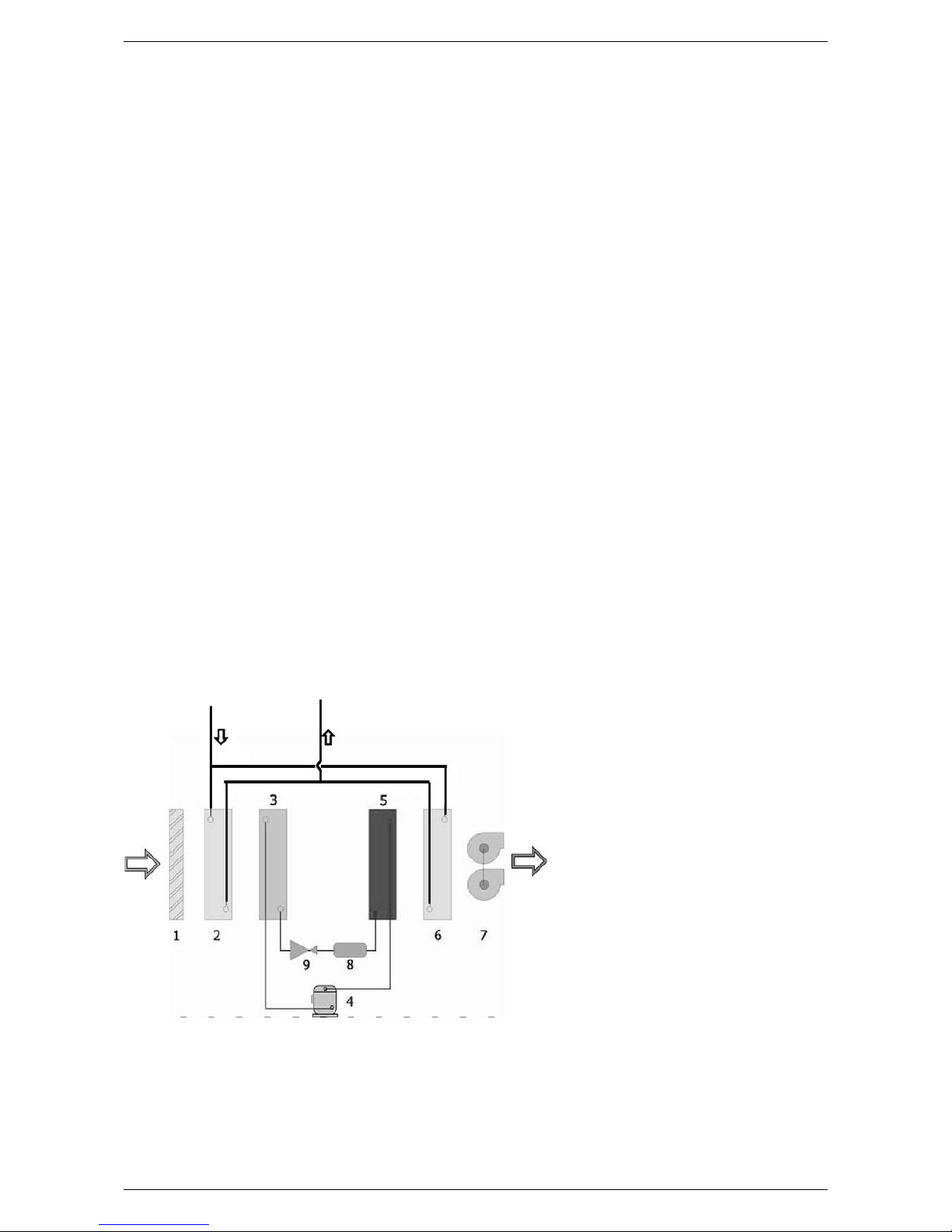
The DMP is an appliance designed to be
coupled with cooling plants with radiant
panels. It is characterised by its silence,
small electricity consumption and high
dehumidification efficiency.
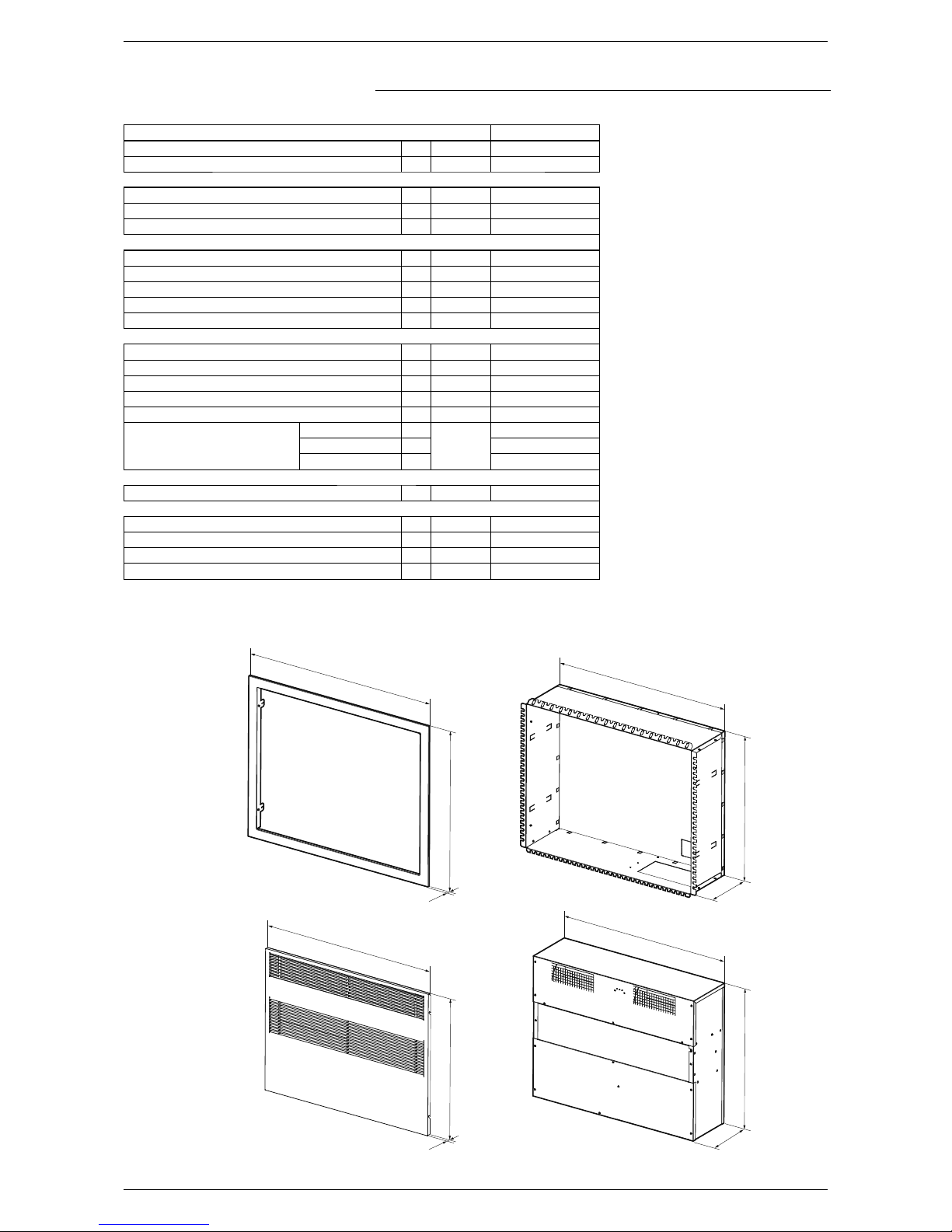
The unit has been designed for vertical
wall installation. However, dangers to the
user or third parties may arise, as well
as damage to the appliance and other
objects, in the event of improper use not
in compliance with the type of use envi-
saged.
Inspection
Any use not expressly indicated in this
manual is not permitted. Consequently
AERMEC will not assume any respon-
sibility for damage that may occur due
to failure to comply with these instruc-
tions.
1.2. PRESERVATION OF THE DO-
CUMENTATION
These installation instructions along with
all the related documentation must be
given to the user of the system, who as-
sumes the responsibility to conserve the
instructions so that they are always at
hand in case of need. READ THIS DOCU-
MENT CAREFULLY, the installation of the
appliance must be carried out by qualified
and suitably prepared staff in complian-
ce with the national legislation effective
in the country of destination. (Ministerial
Decree 329/2004).
The appliance must be installed in such
a way as to enable maintenance and/or
repairs to be carried out. The appliance
warranty does not cover the costs for lad-
der trucks, scaffolding, or other elevation
systems that may become necessary for
carrying out servicing under warranty.
The validity of the warranty shall become
null and void in the event of failure to com-
ply with the above-mentioned indications.
We remind you that the use of products
that employ electrical energy and water
requires that a number of essential sa-
fety rules be followed, including:
−This appliance is not suitable for
use by persons (including children)
with limited physical, sensory, or
mental capacities or those lacking
experience or knowledge, unless
they are supervised or instructed
regarding the use of the appliance
by a person who is responsible for
their safety. Children must always
be supervised to ensure they do
not play with the appliance.
−It is prohibited to carry out any
technical or maintenance ope-
ration before the unit has been
disconnected from the electrical
mains by switching off the master
switch of the system and the main
power switch on the control panel.
−It is prohibited to modify the safety
or adjustment devices without the
manufacturer’s authorisation and
precise instructions
−It is prohibited to pull, detach, or
twist the electrical cables coming
from the unit even if it is disconnec-
ted from the electrical mains.
−It is prohibited to leave any contai-
ners or flammable substances in
the vicinity of the heat pump.
−It is prohibited to touch the applian-
ce when you are barefoot and with
parts of the body that are wet or
damp.
−It is prohibited to open the doors
for accessing the internal parts of
the appliance without first having
turned the master switch "OFF".
−It is prohibited to disperse, aban-
don or leave the packing materials
within the reach of children, as they
are a potential source of danger.
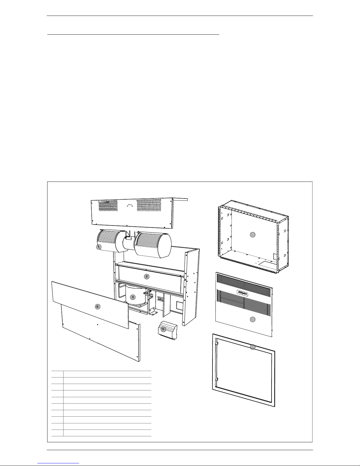
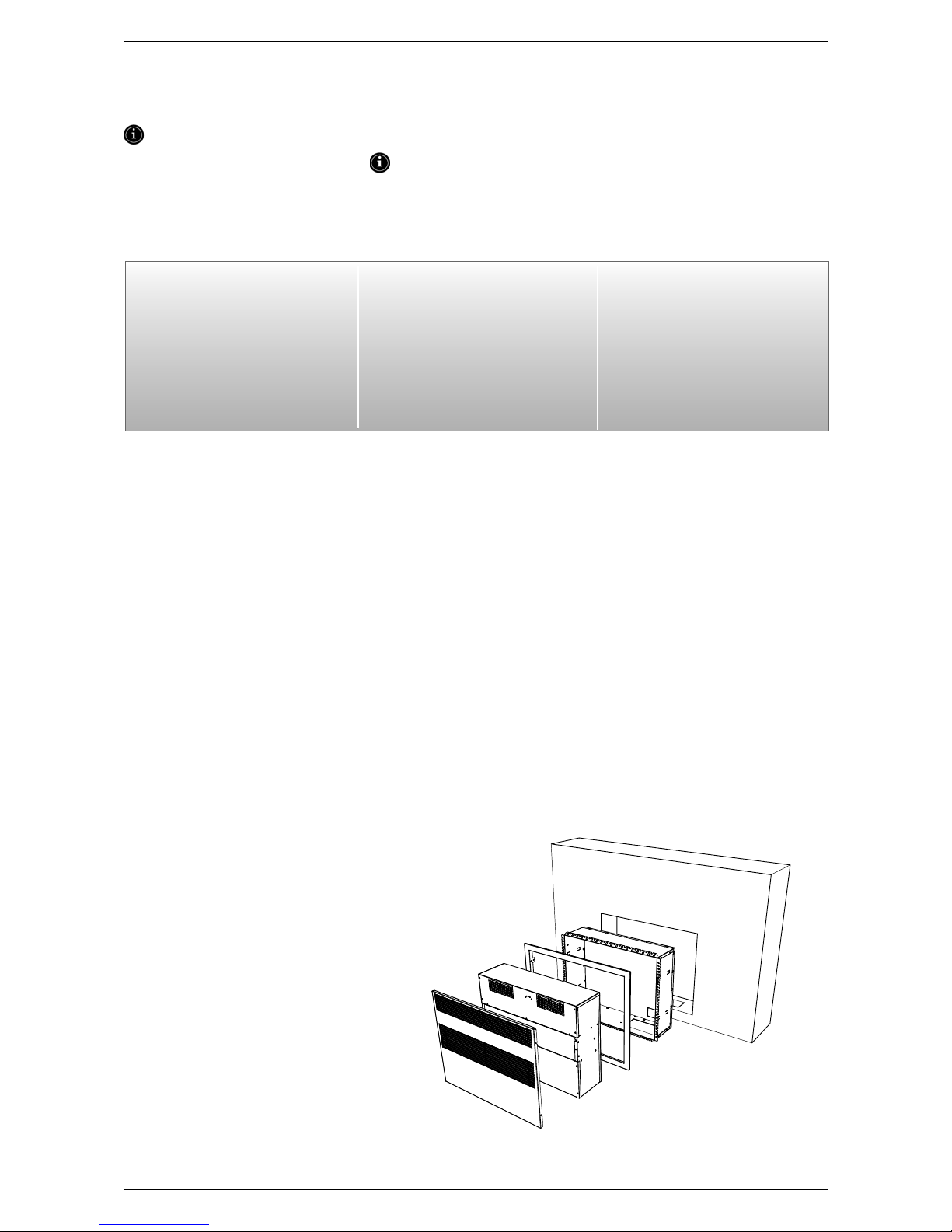
The dehumidifier is supplied in two se-
parate packages:
3.1. MACHINE PACKAGE
−DMP machine with direct front in-
troduction
−Technical instruction, installation
and use manual
−Cardboard box
−Straps
3.2. CASSAFORMA SYSTEM AND
FRONT PANEL PACKAGING
−Cassaforma system that can be as-
sembled
−Front frame + Painted front panel
−Cardboard box
−Straps
NOTE
Tampering, removal, lack of the identifi-
cation plate or other does not allow the
safe identification of the product and
will make any installation or maintenan-
ce operation to be performed difficult.
1. WARNINGS REGARDING DOCUMENTATION
2. FUNDAMENTAL SAFETY RULES
3. PRODUCT IDENTIFICATION

6
4. DESCRIPTION OF THE UNIT
The DMP range dehumidifiers are ap-
pliances designed to be coupled with coo-
ling plants with radiating panels. They are
characterised by silent functioning, small
electricity consumption and high dehumi-
dification efficiency.
The units have been designed for vertical
wall installation. The dehumidifier has an
electrostatically pre-charged air filter and
condensate drip tray, circuit board for
adjustment with remote control panel. It
has a series of pre and post cooling coils
thus guaranteeing optimal performance
and control of the temperature of the
treated air.
However, the units can also function wi-
thout the aid of pre and post cooling wa-
ter coils and this characteristic can be
very useful in the intermediate seasons
when, for example, dehumidification must
be performed with the cooling plant off.
In the winter season the dehumidifier can
be used to accelerate the normal wor-
king conditions of the temperature of the
rooms heated by the radiating plant (fan
only activation - this function is active with
hot water temperature that powers the
coils above 34°C and with room tempe-
rature below 18°C)
The unit is subjected to sealing tests, idle
cycle and is loaded with ecological refri-
gerants. The dehumidifier undergoes a
complete functional inspection before
delivery in order to guarantee the com-
pliance with the European Directives. It
has CE marking and relative certificate of
conformity.
4.1. DESCRIPTION
The DMP is designed to guarantee the
dehumidification of the air in thermically
neutral conditions, i.e. at the same tem-
perature at which is withdrawn. Its pecu-
liarity is that it can be recessed into the
wall, perfectly integrating into the envi-
ronment, both in residential buildings and
tertiary buildings.
7
8
9
KEY
1
Fan
2
Heat exchanger
3
Compressor
4
Air vent valve
5
Microprocessor board
6
Air filter
MANDATORY ACCESSORY (DMP 20GL)
7
Cassaforma system
8
Front closure panel
9
Frame
4.2. DMP EXPLODED DIAGRAM

7
SUMMER CONDITIONS (RADIATING
PLANT IN COOLING FUNCTION
MODE): The humid air is recovered
from the environment by the fan (7),
passes through the electrostatically
pre-charged filter (1) and the pre-
cooled water coil (2) where it is cooled
and taken to a condition near to the
saturation curve and then through the
evaporating coil (3) where it is cooled
further and dehumidified. The air pas-
ses through the condensing coil (5)
where it is post-heated (at constant
humidity) and in the post-cooling coil
(6) where it is taken to the requested
conditions.
WINTER CONDITIONS (RADIATING PLANT IN HEATING FUNCTION MODE): The room air is recovered from the room via the
fan (7), it passes through the electrostatically pre-charged filter (1) and the two water coils (2) and (6) where it is heated. The
cooling circuit is inactive. The integration function to the radiant heating mode only takes place in defined conditions (default:
room air temperature< 18 °C, water coils (2) and (6) powered with water at T > 33 °C, fan at minimum speed). This function can
be disabled/enabled from the remote control panel.
4.2.1. Framework
They are produced in thick hot galvanised
sheet steel, to ensure best resistance
to corrosion. The framework is self-sup-
porting with removable panels in order to
ease inspection and maintenance of in-
ternal components. The condensate drip
tray is supplied as per standard.
Cooling circuit
The cooling circuit includes: Dehydrator
filter, expansion capillary and Schrader
Valves for maintenance and control.
Compressor
The compressor is the hermetic type
with circuit breaker protection relay. The
compressor is assembled on relevant
rubber anti-vibration mounts in order to
guarantee maximum silent functioning.
Condenser and evaporator
The condensing and evaporating coils are
realised in copper pipes and aluminium
louvered fins. The copper pipes have a
diameter of 3/8”. The thickness of the
aluminium louvered fins is 0.2 mm for
the evaporator.
Water coil
The pre and post heating water coils are
realised in copper pipes and aluminium
louvered fins. The copper pipes have a
diameter of 3/8”. The thickness of the
aluminium louvered fins is 0.15 mm. The
pre-cooling coil is used to improve the de-
humidification yield of the unit while the
post-cooling coil is used to control the
temperature of the outlet air from the
unit in a way to send thermically neutral
air into the environment.
DEFROSTING THE EVAPORATING COIL:
The DMP dehumidifier is set in a way to
defrost the heat exchanger according to
the times ser (default setting: 5 minute
defrosting cycle every 50 minutes fun-
ctioning). The timing settings can be mo-
dified from the remote control panel.
The defrosting cycle is actuated by
switching the compressor off, while the
fan is left in function. The compressor
starts again at the end of the defrosting
cycle.
Flow fan
The flow fan is the centrifugal type, di-
rectly coupled with double auger and
three-speed motor. The latest generation
rotors with staggered steps allow silent
functioning.
Electrostatically pre-charged air filter
The dehumidifier is equipped with an elec-
trostatically pre-charged air filter as per
standard. Thanks to its construction de-
tail this filter absorbs and withholds the
suspended dusts: the ideal system for
guaranteeing healthy air for the entire
family.
4.2.2. Electric Control Board
The electric control board can be acces-
sed through the opening in the front pa-
nel of the unit.
Prepared with a terminal board for con-
nection to the power supply network and
for consent via the control panel.
Remote control panel
It is supplied as per standard and con-
trols and adjusts the microprocessor
board and the room temperature and
humidity probe function.
Microprocessor Board
The DMP dehumidifier has a micropro-
cessor board to control compressor ti-
ming, defrosting cycles and the alarms.
It is controlled from the remote panel,
which allows to select fan speed, the
SUMMER/WINTER switch-over function
and to set defrosting cycle times.
AN appropriate board with luminous
LEDS indicates the presence of power
supply voltage, the activation of a defro-
sting cycle or the presence of an alarm.

8
(1) Room temperature 26 °C relati-
ve humidity 65%, coil inlet water
temperature 15°C. Minimum
fan speed.
(2) Maximum conditions: Room tem-
perature 35 °C relative humidity
80%, coil inlet water temperatu-
re 15°C. Minimum fan speed.
(3) Sound pressure level measured
in free field at 1 m from the unit,
directionality factor Q=2, accor-
ding to ISO 3746, minimum fan
speed.
(4) Room temperature 15 °C, coil
inlet water temperature 35 °C.
Minimum fan speed.
DMP20
REFRIGERANT R134a
Gas refrigerant load kg. 0,23
Nominal dehumidification capacity 1 l/24h 20
Nominal power 1W 340
Nominal current 1A 2,3
Dehumidification capacity 2 l/24h 49
Input power 2W 390
Power supply V/Ph/Hz 230/1/50
Nominal current A2,5
Peak current A4
Nominal water flow rate l/h 170
Pressure drops kPa 7
Heating capacity produced - normal heating conditions 4W 1010
Input power 4W 25
Selectable fan speed n° 3
Air flow rate
(minimum speed)
m3/h
200
(average speed) 300
(maximum speed) 380
SOUND DATA
Sound Pressure 3 dB(A) 33
External installation DIMENSIONS
Height mm 590
Width mm 750
Length mm 210
WEIGHT kg 36
5. TECHNICAL DATA
843
771
750
761
678
606590
596
8
18
227
210
FRAME (DMP20GL MANDATORY ACCESSORY)
PANEL CLOSURE
(DMP20GL MANDATORY ACCESSORY)
CASSAFORMA SYSTEM
(DMP20GL MANDATORY ACCESSORY)
DPM20

9
6. OPERATIONAL LIMITS
6.1. FUNCTIONING LIMITS
6.2. HYDRAULIC CIRCUIT
PRESSURE DROPS
°C
100203040
0 %
10 %
20 %
30 %
40 %
50 %
60 %
70 %
80 %
90 %
100 %
Relative humidity %
External air temperature
Water capacity l/h
Pressure drops kPa
ATTENTION
The units are designed and built to
operate with room temperature
from 15°C to 30°C and relative hu-
midity from 30% to 90%. – Inlet wa-
ter maximum temperature in winter
conditions: 60 °C.
It is mandatory to use the units wi-
thin the functioning limits illustrated
in the diagrams shown above. The
warranty becomes immediately null
and void if used in environmental
conditions outside of the stated li-
mits.
Defrosting the evaporating coil
The DMP dehumidifier is set in a
way to defrost the heat exchanger
according to the times ser (default
setting: 5 minute defrosting cycle
every 50 minutes functioning). The
timing settings can be modified from
the remote control panel.
The defrosting cycle is actuated by
switching the compressor off, while
the fan is left in function.
The compressor starts again at the
end of the defrosting cycle.
°C
10 15 20 25
°C
35 40 45
RECOMMENDED INLET WATER TEMPERATURE
Inlet water temperature
Summer conditions
Inlet water temperature
Winter conditions (heating boost)

10
7. SAFETY PRECAUTIONS AND
REGULATIONS
8. INSTALLATION
8.1. CHOICE OF PLACE OF
INSTALLATION
Before installing the unit, check the
integrity of the unit on receipt. The
machine leaves the factory in perfect
state. Any damage must be protested
against immediately to the carrier
and noted on the Delivery Sheet
before signing. AERMEC spa must be
informed regarding the entity of the
damage within 8 days. The Customer
must fill in a written report in the case
of relevant damage.
Handle the packaging using suitable
means so as not to damage the
dehumidifier such as: automatic lifting
systems, metal trolley with wheels
etc. During unloading and positioning
pay great attention to sudden or
violent manoeuvres in order to protect
internal components. The units can be
lifted manually, paying attention not to
damage the lateral and upper panels
of the DMP. It must always be horizon-
tal during these operations. Prepare
a delimited area, suitable for storage
with flat floor or foundation.
−If the dehumidifier must not be used
immediately, store it in a place protec-
ted from atmospheric agents or other
possible causes of damage. The tempe-
rature and humidity limits stated below
must be respected in the place of sto-
rage:
−Temperature d.b.: -10°C ÷ 50°C
−Relative humidity: 20% ÷ 90%
−The selected place must have enough
space to permit all the necessary tube
positionings.
−IT IS mandatory to foresee to the ne-
cessary technical space in order to
allow ROUTINE AND EXTRAORDINARY
MAINTENANCE interventions.
8.2. INSTALLATION PROCEDURE
1. Creation of a niche
2. Installing pipes and cables
3. Assembly of the installation frame and
the surrounding frame
4. Fixing the dehumidifier
5. Execution of the hydraulic and electrical
connections
6. Assembly of the grille
Danger!
The refrigerant circuit is under pressure.
Moreover, very high temperatures can be
reached. The appliance may only be opened
by an SAT service technician or by a quali-
fied technician.
Work on the cooling circuit may only be
carried out by a qualified refrigeration
technician.
GAS R134a
The dehumidifier comes supplied with a
sufficient quantity of R134a refrigerant
gas. This refrigerant is chlorine-free and
does not damage the ozone layer. R134a
is not flammable. However, all maintenance
operations must be carried out exclusively
by a specialised technician using suitable
protective equipment.
Danger of electrical discharge!
Before opening the dehumidifier, complete-
ly disconnect the appliance from the power
mains.
The dehumidifier must be installed
by a QUALIFIED AND SUITABLY TRAI-
NED TECHNICIAN, in compliance with
the national legislation in force in the
country of destination (Ministerial De-
cree 329/2004).
AERMEC will not assume any responsi-
bility for damage due to failure to follow
these instructions.
Before beginning any operation,
READ THESE INSTRUCTIONS CARE-
FULLY AND CARRY OUT THE SAFETY
CHECKS TO REDUCE ALL RISK OF DAN-
GER TO A MINIMUM. All the personnel
involved must have thorough knowled-
ge of the operations and any dangers
that may arise at the moment in which
the installation operations are carried
out.

11
8.3. DIMENSIONS RECOMMEN-
DED FOR THE NICHE
1. Creation of a niche
2. Installing pipes and cables
3. Assembly of the installation frame and
the surrounding frame
4. Fixing the dehumidifier
5. Execution of the hydraulic and electrical
connections
6. Assembly of the grille
The cassaforma system is always sup-
plied separately, disassembled. For as-
sembly, follow the instructions given in
the diagram, using the screws supplied.
ATTENTION
Use protective gloves: possible sharp
edges.
The package also contains the surroun-
ding frame and the front panel.
Once the cassaforma system compo-
nents have been removed, close the
cardboard packaging paying attention
to keep the surrounding frame and
front panel integral.
Before wall-recessing the cassaforma
system, after having made a suitable
niche in the wall, open the pre-cut ele-
ments on the side to ease fixing.
Insert the cassaforma system into the
niche.
8.3.1. ASSEMBLY OF THE FRONT
FRAME
Insert and fix the cassaforma system
into the wall niche.
Carry out filling and plaster the wall.
NOTE
The front profile of the cassaforma
system must be flush with the fini-
shed plaster of the wall. Use appro-
priate filling and finishing material.
DO NOT DEFORM THE CASSAFOR-
MA SYSTEM. THE CASSAFORMA SY-
STEM IS NOT A SUPPORTING STRUC-
TURE!
Now it is possible to fix the front frame.
Follow the illustrated phases and use
the screws supplied.
Now insert the dehumidifier into the
cassaforma system.
The recess unit is designed for inser-
830
240
640
7
1
3
4
5
6
2

12
tion of pipes and cables inside the in-
stallation frame.
Pipes and cables must have a length
such to allow successive connections
to the dehumidifier.
Fix the dehumidifier to the cassaforma
system using the supplied screws, as
indicated in the image on the right.
Prevent dirt or other from entering the
pipes. Protect the pipes during the as-
sembly phase of the installation frame.
Make the hydraulic and electric con-
nections after having mounted the de-
humidifier.
8.3.2. CONDENSATE DRAIN PIPE
CONNECTION
The connection of the condensate drain
on the dehumidifier must be made via
the rubber tube fixed to the fitting with
external diameter of 20 mm positioned
on the front panel of the unit. A siphon
must be realised in the drain line, as il-
lustrated in the figure.
8.4. HYDRAULIC CONNECTION TO
THE WATER COIL
The dehumidifier must be connected to
the refrigerated water plant in order to
guarantee the introduction of neutral
conditioned air into the environment.
The connection is made using the ½”
FEMALE attachments installed on the
unit.
Water inlet: “IN” label. Water outlet:
“OUT” label.
All hydraulic connections must be made
by qualified staff and in compliance with
local regulations in force.
Condensate
Drain

13
8.5. ELECTRIC CONNECTIONS
All the electrical opera-
tions must be carried
out by STAFF IN POS-
SESSION OF THE NE-
CESSARY QUALIFICA-
TIONS BY LAW suitably
trained and informed
on the risks related to
these operations.
The characteristics of the
electrical lines and of the
related components must
be determined by STAFF
QUALIFIED TO DESIGN
ELECTRICAL SYSTEMS,
in compliance with the in-
ternational and national
regulations of the place of
installation of the unit and
in compliance with the re-
gulations in force at the
moment of installation
For the installation re-
fer only to the wiring
diagram supplied with
the appliance. The
electrical diagram
along with the manuals
must be kept in good
condition and ALWAYS
AVAILABLE FOR ANY
FUTURE SERVICING
ON THE UNIT.
It is mandatory to veri-
fy that the machine is
watertight before ma-
king the electrical con-
nections and it must
only be powered up
after the hydraulic and
electrical works have
been completed.
The DMP is completely wired and only
requires connection to the electric po-
wer supply network. Please verify that
the electrical mains features are suita-
ble for the absorption values indicated
in the electrical data table, also taking
into consideration any other machines
operating at the same time.
−The electric power supply must
respect the limits stated: if this is
not the case, the warranty will im-
mediately become null and void. Al-
ways check that the electric power
supply is disconnected before star-
ting any operation.
−The unit can only be activated cor-
rectly if the remote dehumidifica-
tion and ventilation remote consent
have been connected (connections
to the remote control panel sup-
plied). Regarding this, scrupulously
follow that stated in the wiring dia-
gram.
8.6. START-UP
Before start-up, check the electric
connection and the correct fixing of all
clamps.
• The power supply voltage must be
that stated on the unit plate
• Check that there are no gas leaks.
• Check that all hydraulic connections
have been installed correctly and that
the indications on the plate have been
respected.
• Before switch-on, check that all clo-
sure panels are in their position with
relevant screw fasteners.
If the unit does not start:
Check that the remote consent con-
tacts are enabled.
WARNING: Do not modify the unit elec-
tric connections or the warranty will
become immediately null and void.
8.6.1. ELECTRIC CONNECTIONS
CP compressor
DCP adjuster circuit board
F1 fuse isolator switch
IG Master switch
L Phase
M Terminal board
MV Fan
N Neutral
PE Earth connection
B3 NTC water probe
PN Multi-function wall panel
Fan single-phase motor
1 = blue =common
2 = black =high
3 = brown = average
4 = red = low
5 = --------
6 = y/green
Signal
LED
Cable
Flat
blue
black
brown
red
black MAX speed
brown AVERAGE speed
RED MINIMUM
Speed
PROTECTION NOT SUPPLIED

14
8.7. GENERAL FUNCTIONS
CONTROL BOARD
The regulator is prepared for mana-
gement of different machine models
depending on the position of the DIP
switches present on the control.
To select the AIR-CONDITIONING mo-
del, the DIP switches must be set ac-
cording to the layout shown here. The
control and all loads must be discon-
nected from the main power supply.
8.8. TERMINALS CONNECTION
NETWORK - CONTROLS.
8.8.1. Electric connections
Shielded and twisted bipolar cables
must be used to connect the terminals
to the control or the controls network,
at the relative clamps indicated on the
terminal and on the control panel.
The maximum distance from the termi-
nal from the relative control is 30 m.
The power supply voltage is 24 Vdc
with data transmission on the twisted
pair connection cable with packs at a
transmission speed of 4800 bit/s and
proprietor protocol.
8.8.2. IO list: electrical data
The platform for control of the forced
air heaters envisions a base board,
developed with a layout for the maxi-
mum configuration, which will then be
mounted in the different versions to ge-
nerate different product codes depen-
ding on the requests and applications.
All parameters will be configurable and
many functions present can be acti-
vated according to requirements and
applications.
The inputs and outputs will all be con-
figurable via software in the different
functionalities for greater flexibility and
easy installation.
Below find the IO table with electric
data for every input and output. The
configuration default values relative to
the model are specified below in the
"Default configurations" chapter
ON
OFF
12345678
8.8.3. High voltage terminal board
Type # N° Ter-
minal Code Description Electric features at nominal
voltage NOTES
X1
11L Power supply line
230 Vac +10%, -15 % at 50 Hz.
Max. absorption 8 VA (without addi-
tional loads) to confirm
Screw Terminal Board
22N Neutral power supply
Screw Terminal Board
33EARTH Service earth
Screw Terminal Board
X2
14Compressor control faston Max passage current on contact =
20A with resistive load
Potential free con-
tact on Power Relay
25CK4 Compressor control faston
36Common Relay Reference
47Common Relay Reference
58Common Relay Reference
69Common Relay Reference
710 CK3 Fan 3 speed control Max output current on contact =
5A with resistive load
Max total current for all digital
outputs = 10°
Potential free
contact
811 CK2 Fan 2 speed control
912 CK1 Fan 1 speed control
10 13 Line Relay voltage
Power supply
voltage for the
loads
X7
124 CE+ TTL terminal serial connection
225 CE- TTL terminal serial connection
X5
130 B1-NTC NTC1
NTC 10 kΩat 25 °C, ß = 3435 (clamps
9 – 10)
231 B1-NTC NTC1
332 B2-NTC NTC2
433 B2-NTC NTC2

15
X6
134 B3-
MULTI MULTI In NTC: clamps 1 -2, jumper between
1 and 2
In. 0..10 V max input current = 0.75 mA
(clamps 2 – 3, jumper disconnected)
In. 4..20 mA (clamps 2 – 3,
jumper between 2 and 3)
235 B3-
MULTI MULTI
336 B3-
MULTI MULTI
X3
121 TX-RX+ RS485 serial
222 TX-RX- RS485 serial
323 GND Reference for serial
X4
126 D1
D1 digital input
Max voltage towards GND with input open
= 24 Vdc
227 GND1
ID1 digital input reference
328 D2
D2 digital input
Max current towards GND with contact
closed = 6.5 mA
Min current towards GND with contact
closed = 3 mA
429 GND2
ID1 digital input reference
SV1 LED Connection flat to the external
LED synoptic 10 poles on flat
8.9. INPUTS AND OUTPUTS
INPUTS
WS water temperature probe. Optional and can be set from the terminal, used for the consent for dehumidification and
for the "Booster" function.
OUTPUTS
FAN1 fan 230 Vac on/off control output speed 1
FAN2 fan 230 Vac on/off control output speed 2
FAN3 fan 230 Vac on/off control output speed 3
CP compressor 230 Vac on/off control output on Triac
8.10. DEHUMIDIFICATION FUN-
CTIONING LOGIC FUNCTION
When the summer (dRY) mode is se-
lected, if the humidity detected is grea-
ter than the humidity set point, the FAN
output is activated and after 30” (“de-
lay CP 30” parameter) the compressor
control CP output is activated. When
exiting this mode or the humidity con-
ditions do not require dehumidification
(humidity detected lower than set point
humidity - differential for dehumidifica-
tion), the compressor stops and after
30” the fan output also stops FAN (“De-
lay FAN 10” parameter).
The activation of ventilation and of the
compressor can also depend on the
temperature of the plant water when a
water temperature probe is set. In this
case, only if the temperature of the wa-
ter is lower than a water set point (less
hysterisis of 1°C) will the dehumidifica-
tion parts start to function.
IMPORTANT: every time the compres-
sor switches on it must remain active
for a minimum time fixed by the “Cycle
CP ON 300” ” parameter, even if there
is no consent from the humidistat.
The FAN always switches off after the
CP compressor, unless managed by
the "Booster" function.
8.11. DEFROST FUNCTIONING
Timed compressor functioning for eva-
porating coil defrosting: compressor
switch off for a time equal to "Defrost
Duration" every interval of time equal to
“Time between Defrost" with fan active.
Whenever compressor consent is mis-
sing during the defrost cycle (whether
because the humidistat set point has
been reached or for the passage to the
Winter of Stand-by mode), the defrost
timing continues and remains indicated
by the . symbol. In this case any re-
quest for activation of the compressor
will not be performed until the end of
defrost timing, (Defrost Duration).
N.B.: Defrost has priority over the mini-
mum functioning time of the compres-
sor “Cycle CP ON 300” ”.
8.12. WINTER FUNCTIONING
MODE
„BOOSTER“ function: If the room tem-
perature is < 18 °C and the temperatu-
re of the water that feeds the machine
coils (WS) is > 33 °C, the fan functions

16
at the speed set until reaching the 18
°C of the room.
8.13. FAN SPEED ADJUSTMENT
To select the speed at which the fan
must function in the case of request
(both humidistat and Booster) in any
functioning mode, using the and
keys it is possible to select the three
fan speeds.
REMEMBER IT IS IMPORTANT TO SE-
LECT THE SLOWEST SPEED FOR OP-
TIMUM DEHUMIDIFICATION.
8.13.1. terminal probes calibration
The temperature and humidity probes
present on the terminal can be calibra-
ted with a constant value (in positive
and in negative) over the entire measu-
rement range. This value id 5°C for the
temperature and 10% RH for humidity.
To do this, the relative parameter must
be modified (see table above).
The humidity probe also has an internal
algorithm based on humidity, tempera-
ture and calibration value of the tempe-
rature. This algorithm is not active by
default. To activate it use the relative
parameter (184), as in the previous
table. Use this algorithm in the case in
which the direct compensation by me-
ans of parameter is not sufficient.
8.14. DEFAULT CONFIGURATIONS
The following inputs and outputs are
set For the AIR-CONDITIONING version.
8.15. ERROR SYMBOLS
The error signals are divided into “Com-
munication errors” and “Alarm signals”.
8.15.1. Communication errors
The communication errors detect com-
munication errors between the termi-
nal and control.
They are shown on the display by “Er:”
followed by the error code described
below.
• Er:24 no control detected
• Er:25 no response after the initial
transmission of the parameters
• Er:26 no response from the control
with valid alignment parameters
• Er:27 loss of network control
• Er:29 incorrect alignment between
controls and relative expansions,
both in number and address
• Er:30 loss of communication
between terminal and control
In the presence of these errors (Er:24...
Er29), check the machine hardware
settings (DIP switch) and the correct
connection of the terminal power sup-
ply cables (CE+ and CE-) and re-start
the machine.
In the case of “Er:30” on exiting the
programming of one or more parame-
ters, after machine re-start these may
have to be reprogrammed.
After programming, first switch the
machine off, wait 20 seconds to allow
the settings to be saved in the perma-
nent memory inside the control.
8.15.2. Alarm signal
The alarm signals detect errors on the
probes present (if set) and on the set-
tings of the machine itself.
They are displayed on the screen by “E”
followed by the number of the control
that detected the error and the error
code itself, as described below.
“Ex:yy” with x that varies from 0 to 7,
indicates that the error with code yy
has been detected on the control with
address x(selected using selector
switches 1, 2 and 3 of the DIP switch
on the same control).
Error codes (yy):
• 02: water coil temperature probe
breakdown
• 12: terminal room temperature
probe breakdown
Example: The “E0:06” signal indicates
that an error has occurred on the room
temperature probe on the control devi-
ce with address 0 (code 06).
In the presence of these errors, check
that the probes configured (manually
or default settings) are present, con-
nected correctly and functioning. The
error disappears on connection or
replacement of the probe (even with
machine on and running) or on re-pro-
gramming of the parameter relative to
the output (changing the type of probe
or resetting the parameter, indicating
the absence of the probe).
Parameter Description
Ch 3 B3 probe
type
Coil Water Tempera-
ture (WS)
Ch 4 B4 probe
type
Evaporator Tempera-
ture (SE)
Ch Q1 output
type
Fan 1 speed control
(FAN1)
Ch Q2 output
type
Fan 2 speed control
(FAN2)
Ch Q3 output
type
Fan 3 speed control
(FAN3)
Ch TR1 output
type
Compressor Control
(CP)
Ch Analogue
signal output
type
0-10V Y1
ON/OFF Remote
Alarm (0..10V)

17
8.16. LED PANEL
The LED panel must be connected to
the low voltage control terminal board
(green connectors) at the clamps indi-
cated in the following layout:
8.17. DEHUMIDIFIER LED INTERFA-
CE CONNECTION LAYOUT
The green LED indicates the board po-
wer supply.
The blue LED indicates compressor
activation. If it flashes it indicates the
defrost cycle is in progress.
The red LED indicates the presence of
an alarm signal. In this case the LCD
terminal display which specific signal is
present.
8.18. FRONT PANEL INSERTION
When the dehumidifier has been inser-
ted and the electric and hydraulic con-
nections and the connection to the wall
remote control panel have been made,
insert the front panel in the surroun-
ding frame.
8.19. REMOVAL OF THE FRONT
PANEL
Use two aluminium hooks to remove
the front panel. Place them between
the upper fins and centre in correspon-
dence with the vertical pipes. The panel
slides out by pulling upwards.
NOT
CONNECTED
DEHUMIDIFIER LED INTERFACE
CONNECTION LAYOUT

18
9. MAINTENANCE
10. IMPROPER USE
9.1. PERIODICAL CLEANING OF
THE AIR FILTER
Periodically clean the air filter (at least
once a month when used). Remove the
front panel and slide the filter out.
The filter is cleaned by sucking the ex-
ternal surface using a suction device.
DO NOT WASH THE FILTER!
9.2. PUTTING OUT OF SERVICE
When the unit must be replaced, some
recommendations must be followed:
• The refrigerant must be recovered
by specialised staff and sent to col-
lection centres;
• the compressor lubricant oil must
also be collected and sent to collec-
tion centres;
• the unusable parts of the structure
and the various components must
be demolished and divided accor-
ding to their nature; particularly the
copper and the aluminium present
in a discrete quantity in the machi-
ne.
These operations ease the recovery
and recycling of the substances, thus
reducing environmental impact.
9.3. TROUBLESHOOTING
WARNING: Regarding solutions, pay ex-
treme attention in the operations to be
carried out: excessive safety can cau-
se accidents, even serious, to unskilled
persons. It is therefore recommended
that once the cause has been identified
to request our intervention or that of
qualified technicians.
PROBLEM PROBABLE CAUSE POSSIBLE SOLUTION
The unit does not start
• No electric power supply
• Line switch open
• Remote consent open
• Faulty circuit board
• Connect the unit to the electric
power supply
• Close the line switch
• Close the consent
• Replace the board
The fan starts-up but the compressor does not
• Compressor circuit breaker
intervened
• Faulty compressor
• Faulty circuit board
• Wait for the compressor to cool
down and try again
• Replace the compressor
• Replace the board

19
CHRONO 19 USER MANUAL
10.1. DESCRIPTION OF THE PANEL
Allows to display and modify
the set points of the relative
humidity requested, they mo-
dify the set speed and all set
point values.
They activate the selection
function of the set speed.
The value 0 indicates the
selection of the automatic
fan function.
Setting the functioning
mode in dehumidification
and heating mode.
MODE: allows to select the
unit functioning MODE, in
automatic.
Unit ON/ OFF.
Confirm
Programming and info
menu (in its sub-menus it is
also used to go back to the
main page))
Enable timed functions
(PARTY and VACANZA)
10.2. COMMISSIONING
The first time the CHRONO 19 is
switched on the display shows the
CLOW signal (the backup capacity is
not sufficiently loaded). To access the
info menu, wait a few minutes. The time
necessary for the backup capacity to
accumulate a minimum load sufficient
for functioning.
10.3. FUNCTIONING MODE
By pressing the MODE key one of
the following unit functioning modes
can be set:
AUTOMATIC MODE:
1. Selecting AUTOMATIC the .
symbols are shown on the display.
The unit satisfies the dehumidi-
fication requests depending on
the programmed times. The time
period pathway is indicated by
the flashing on
the program phase cursor) and
specific if the level is comfort
or economy . During the time
period when the unit remains in
OFF (standby), the cursor does
not flash and the CHRONO 19
goes into stand by. As well as the
symbol that characterises the au-
tomatic function, . is added.
MODIFICATION:
During functioning in automatic mode
by acting on the and keys, it is
possible to manually modify the level
set by the program or disable functio-
ning entirely.
This temporary modification is indica-
ted with the flashing symbol and
lasts until the next time period.
The level selected is indicated by the
respective symbol:
the main window display is the following:
MODO SYMBOLS ON
AUTOMATIC
MODE SYMBOLS ON
COMFORT

20
By pressing the . key one of the fol-
lowing unit functioning modes can be
set:
• Selecting DEHUMIDIFY MANUAL
the display shows the flashingi
, and symbols. The unit
satisfies the dehumidification re-
quests depending on the comfort
humidity set.
• Selecting HEATING MANUAL the
display shows the flashing , and
symbols. The unit satisfies the
heating requests depending on the
temperature set managing the BO-
OSTER function whenever the rela-
tive probe is set.
• Selecting OFF the display shows
the . The unit stays off, ignoring
any request.
• The symbol will activate during
defrosting.
By pressing the key all fun-
ctions are disabled: Only the
symbol will be on. By pressing the
key again, go back to the
mode before switch off.
• The symbol will activate during
defrosting.
By pressing the key all fun-
ctions are disabled: Only the
symbol will be on. By pressing the
key again, go back to the
mode before switch off.
• Selecting HEATING MANUAL the
display shows the flashing and
symbols and the wording
. The unit satisfies the heating re-
quests depending on the tempera-
ture set and the display will be
.
10.4. SETTINGS MENU
By pressing the key enter the
INFO – settings menu.
Always use the key to scroll the
menu. To enter/modify press the
key.
• COMFR (Comfort) Set the humi-
dity set point for the comfort level
(the set point will be memorised).
• ECONM (Economy) Set the humi-
dity set point for the economy level
(the set point will be memorised).
• TIME (Time) Clock setting.
• PROG (Time setting)
Set the weekly time programming.
• ESCAPE
At the end of the menu there is the au-
tomatic exit from the INFO – settings
menu.
10.5. CLOCK (TIME)
To adjust the clock, enter the settings
menu by pressing the key.
Scroll the menu up to TIME and press
the key to access the sub-menu.
Using the and keys the time can
be changed. To pass to modifying the
minutes, press the key and in the
same way to modify the day.
To confirm the modifications made,
press the key (go back to the main
page automatically).
10.6. WEEKLY TIMER PROGRAM-
MING
In order to modify the weekly time set-
ting of functioning in dehumidification
mode, press the key to enter the
settings mode.
Successively reach the programming
menu by repeatedly pressing the
key. To enter the time programming
menu, press the key.
The time programming allows to set
automatic functioning of the unit in
dehumidification mode in determined
time periods and on determined days
of the week, selecting the level of humi-
dity for each time period.
The unit functioning settings can be
made for
individual
settings or for
groups
of several consecutive days.
10.6.1. Individual days
There are 4 time periods available for
each individual day selected (4 switch-
on/off periods of the unit in dehumidi-
fication mode, also at different times
from day to day), as shown in the table
that follows: Act as follows to set an in-
dividual time period:
MODE SYMBOLS ON
dehumidify
manual
heating
manual
FACTORY-SET VALUES
On 1 Off1 On 2 Off 2 On 3 Off 3 On 4 Off 4
MONDY day 1 monday 6:30 8:00 11:00 13:00 17:00 23:00 24:00 24:00
TUEDY day 2 tuesday 6:30 8:00 11:00 13:00 17:00 23:00 24:00 24:00
WEDDY day 3 wednesday 6:30 8:00 11:00 13:00 17:00 23:00 24:00 24:00
THUDY
day 4 thursday 6:30 8:00 11:00 13:00 17:00 23:00 24:00 24:00
FRIDY day 5 friday 6:30 8:00 11:00 13:00 17:00 23:00 24:00 24:00
SATDY day 6 saturday 6:30 8:00 11:00 13:00 17:00 23:00 24:00 24:00
SUNDY day 7 sunday 6:30 8:00 11:00 13:00 17:00 23:00 24:00 24:00
Table of contents
Languages:
Other AERMEC Dehumidifier manuals