manuals.online logo
Brands
  1. Home
  2. •
  3. Brands
  4. •
  5. AERMEC
  6. •
  7. Heat Pump
  8. •
  9. AERMEC NRA-C User manual

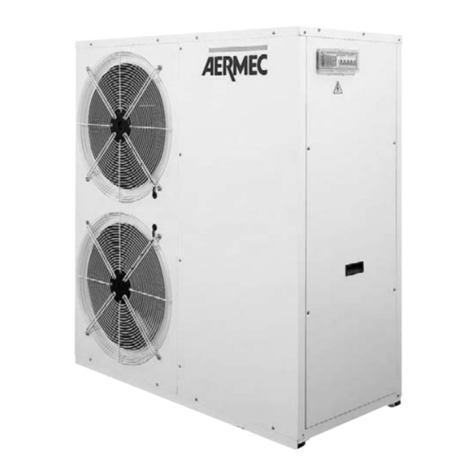
AERMEC NRA-C User manual

AERMEC S.P.A.
ISO 9001 - Cert. nº 0128/1
C
E
R
T
I
F
I
E
D
Q
U
A
L
I
T
Y
S
Y
S
T
E
M
INRACUW
9805
65010.06
Unità motocondensanti raffreddate ad aria
Air cooled condensing unit
NRA-C
R22 - R407C
MANUALE UNICO
•
BOOKLET
Sostituisce il:
Replace:
65010.04 / 9801
3
INDICE
•
CONTENTS
INFORMAZIONI GENERALI
•
GENERAL INFORMATION
4
CARATTERISTICHE
•
FEATURES
Descrizione dell’unità •
Unit Description
Scopo della macchina •
Purpose of the machine
Versioni disponibili •
Versions available
6
Descrizione dei componenti •
Description of components
Organi di sicurezza e regolazione •
Safety and control devices
7
Imballo •
Packing
Accessori •
Accessories
Tabella compatibilità accessori •
Accessory compatibility table
Criteri di scelta •
Selection
8
Dati tecnici •
Technical data
9
Rese frigorifere •
Cooling capacities
14
Fattori di correzione •
Correction factors
Linee frigorifere •
Refrigerant lines
17
Pressione e potenza sonora •
Sound pressure and power levels
Tarature •
Settings
18
Limiti operativi di funzionamento •
Operating limits
19
MISURE DI SICUREZZA
•
SAFETY MEASURES
Usi impropri •
Improper uses
Anomalie di funzionamento •
Malfunctions
Simboli di sicurezza •
Safety symbols
20
INSTALLAZIONE
•
INSTALLATION
Trasporto •
Carriage
Ubicazione •
Positioning
21
Collegamenti elettrici •
Wiring connections
Prima della messa in funzione •
Before start-up
22
CARATTERISTICHE
•
FEATURES
Dati dimensionali •
Dimensions
Posizione attacchi frigoriferi •
Position of refrigerant connections
23
Spazi tecnici minimi •
Minimum technical space
Dati accessori •
Accessories data
25
Circuiti frigoriferi •
Refrigerant circuits
26
Schemi elettrici •
Wiring diagrams
28
5
INFORMAZIONI GENERALI
•
GENERAL INFORMATION
OSSERVAZIONI
Conservare il manuale in luogo asciutto, per evitare il
deterioramento, per almeno 10 anni per eventuali riferimen-
ti futuri.
Leggere attentamente e completamente tutte le informa-
zioni contenute in questo manuale.
Prestare particolarmente attenzione alle norme d’uso
accompagnate dalle scritte “PERICOLO” o “ATTENZIO-
NE” in quanto, se non osservate, possono causare danno
alla macchina e/o a persone e cose.
Per anomalie non contemplate da questo manuale, interpel-
lare tempestivamente il Servizio Assistenza di zona.
AERMEC S.p.A. declina ogni responsabilità per qualsiasi
danno dovuto ad un uso improprio della macchina, ad una
lettura parziale o superficiale delle informazioni contenute
in questo manuale.
Il numero di pagine di questo manuale è: 44.
REMARKS
Store the manual in a dry location to avoid deterioration, as
they must be kept for at least 10 years for any future referen-
ce.
All the information in this manual must be carefully read
and understood.
Pay particular attention to the operating standards with
“DANGER” or “WARNING” signals as their disrespect can
cause damage to the machine and/or persons or objects.
If any malfunctions are not included in this manual, contact
the local Aftersales Service immediately.
AERMEC S.p.A. declines all responsibility for any damage
whatsoever caused by improper use of the machine, and a
partial or superficial acquaintance with the information con-
tained in this manual.
This manual has 44 pages.
AERMEC S.p.A.
37040 Bevilacqua (VR) Italia – Via Roma, 44
Tel. (0442) 633111
Telefax (0442) 93730 – 93566
È fatto divieto di mettere in servizio la macchina, oggetto della
Dichiarazione, prima che la macchina a cui sarà incorporata od
assiemata sia stata dichiarata conforme alle disposizioni della
Direttiva.
Dichiarazione di conformità
Noi, firmatari della presente, dichiariamo sotto la nostra
esclusiva responsabilità, che la macchina in oggetto è
conforme a quanto prescritto dalla Direttiva 89/392/CEE,
91/368/CEE, 93/44/CEE, 93/68/CEE e dalle Normative UNI
9018 ed EN 60335-2-40 e 60204-1.
It is not allowed to operate the appliance object of the
Declaration before the appliance it will be incorporated to or
assembled with, is declared in compliance with the provisions of
the Directive.
Declaration of conformity
We declare under our own responsability that the above
equipment complies with provisions of Standard
89/392/EEC, 91/368/EEC, 93/44/EEC, 93/68/EEC and
Regulation UNI 9018 and EN 60335-2-40 and 60204-1.
modello
- model:
numero di serie
- serial number:
NRA-C
Bevilacqua, 1/1/1998
La Direzione Generale •
General Management
Alessandro RIELLO
6
CARATTERISTICHE
•
FEATURES
1
32
6
8
5
7
4
DESCRIZIONE DELL’UNITÀ
SCOPO DELLA MACCHINA
Le unità motocondensanti della serie NRA-C sono state rea-
lizzate per soddisfare le esigenze delle medie e piccole
utenze per usi civili ed industriali.
VERSIONI DISPONIBILI
Grandezze disponibili con gas R22 (bicompressore):
NRA-C 202 - 252 - 302 - 352 - 402 - 502
Grandezze disponibili con gas R22 (monocompressore):
NRA-C 201 - 251 - 301
Grandezze disponibili con gas R407C:
NRA-C 2027 - 2527 - 3027 - 3527 - 4027 - 5027
UNIT DESCRIPTION
PURPOSE OF THE MACHINE
The NRA-C series of condensing units have been designed
to satisfy the needs of small to medium sized civil and indu-
strial installations.
VERSIONS AVAILABLE
Sizes available with gas R22 (bicompressor):
NRA-C 202 - 252 - 302 - 352 - 402 - 502
Sizes available with gas R22 (monocompressor):
NRA-C 201 - 251 - 301
Sizes available with gas R407C:
NRA-C 2027 - 2527 - 3027 - 3527 - 4027 - 5027
1Scambiatore lato aria •
Air side exchanger
2Compressore •
Compressor
3Filtro deidratatore •
Filter dryer
4Pressostato di alta •
High pressure switch
5Spia del liquido •
Sight glass
6Quadro elettrico •
Switchboard
7Struttura portante •
Channel frame
8Gruppo ventilante •
Fan group
COMPONENTI PRINCIPALI •
MAIN COMPONENTS
NRA 302 C
7
CARATTERISTICHE
•
FEATURES
DESCRIZIONE DEI COMPONENTI
1 SCAMBIATORE LATO ARIA
È realizzato con tubi di rame ed alette in alluminio bloccate
mediante espansione meccanica dei tubi.
È del tipo ad alta efficienza (alette intagliate).
2 COMPRESSORE
Di tipo ermetico alternativo o scroll a seconda dei modelli,
è dotato di cuffia fono-isolante ed il vano compressori è iso-
lato acusticamente.
3 FILTRO DEIDRATATORE
Di tipo meccanico realizzato in ceramica e materiale igro-
scopico, è in grado di trattenere le impurità e le eventuali
tracce di umidità presenti nel circuito frigorifero.
4 PRESSOSTATO DI ALTA
A taratura fissa, posto sul lato ad alta pressione del circuito
frigorifero, arresta il funzionamento del compressore in caso
di pressioni anomale di lavoro.
5 SPIA DEL LIQUIDO
Serve per verificare la carica di gas frigorigeno e l’eventuale
presenza di umidità nel circuito frigorifero.
6 QUADRO ELETTRICO
Contiene la sezione di potenza e la gestione dei controlli e
delle sicurezze.
È conforme alle norme EN 60204-1, EN 60335-2-40, IEC
801-4 livello 3.
7 STRUTTURA PORTANTE
Realizzata in lamiera di acciaio zincata a caldo, di adegua-
to spessore, è verniciata con polveri epossidiche per garan-
tire la resistenza agli agenti atmosferici.
8 GRUPPI VENTILANTI
Di tipo elicoidale, bilanciati staticamente e dinamicamente,
sono direttamente calettati sull’albero del motore.
Gli elettroventilatori sono protetti con interruttori magneto-
termici e con griglie metalliche fissate sulla parte superiore
della carpenteria.
- RUBINETTO LIQUIDO
Consente di intercettare il gas refrigerante in caso di manu-
tenzione straordinaria.
- PRESSOSTATO DI BASSA
A taratura fissa, posto sul lato a bassa pressione del circuito
frigorifero, arresta il funzionamento del compressore in caso
di pressioni anomale di lavoro.
- SILENZIATORE
Posto sulla mandata del compressore, serve ad attenuare le
pulsazioni causate dal moto del gas.
Non è presente se il compressore è di tipo Scroll.
ORGANI DI SICUREZZA E REGOLAZIONE
- Sistema di interblocco porta.
- Magnetotermico protezione compressori.
- Magnetotermico protezione ventilatori.
- Magnetotermico protezione ausiliario.
- Contattori alimentazione compressori.
- Contattori alimentazione ventilatori.
-Resistenza carter compressori (escluso NRA 352 C - 3527
C - 201 C - 251 C).
- Pressostati di bassa e alta pressione.
-È inoltre possibile portare a distanza i seguenti comandi e
segnalazioni:
interruttore acceso/spento;
pulsante di avviamento;
lampade per la segnalazione del blocco;
lampade per la segnalazione del funzionamento;
l’ingresso per il consenso di funzionamento.
Fare riferimento agli schemi elettrici a bordo macchina.
COMPONENT DESCRIPTION
1 AIR SIDE EXCHANGER
Made of aluminium fins mechanically bonded to copper
pipes.
High efficiency coil (slotted fins).
2 COMPRESSOR
Hermetic compressors either reciprocating or scroll depen-
ding on the models, all the compressors are fitted with an
acoustic jacket. The compressor housing is soundproofed.
3 FILTER DRYER
A mechanical filter in ceramic and hygroscopic material,
capable of retaining the impurities and any traces of humi-
dity present in the refrigerant circuit.
4 HIGH PRESSURE SWITCH
With a fixed calibration, mounted on the high pressure side
of the refrigerant circuit, it blocks operation of the compres-
sor in the event of abnormal working pressures.
5 SIGHT GLASS
Checks refrigerant gas charge status and for presence of
moisture in the cooling circuit.
6 SWITCHBOARD
It contains the power section and the management of the
controls and safeties. It has conform to EN 60204-1, EN
60335-2-40, IEC 801-4 level 3.
7 CHANNEL FRAME
Made of hot galvanised steel sheet, of substantial thickness,
it is painted with epoxy powder to guarantee a long-term
weather resistance.
8 FAN GROUP
Propeller fans, statically and dynamically balanced, they are
directly coupled to the motor shaft.
The fans are protected by a circuit breaker and metal guard
fixed to the top of the housing.
- LIQUID CUT-OFF VALVE
It permits the refrigerant flow to be cut-off during repair
work.
- LOW PRESSURE SWITCH
With fixed calibration, it is mounted on the low pressure
side of the refrigerant circuit, it blocks the compressor in the
event of abnormal working pressures.
- MUFFLER
Installed on compressor delivery line, the silencer dampens
pulsations caused by gas movement.
Not present on Scroll type compressors.
SAFETY AND CONTROL DEVICES
- safety door interlock system.
- compressor circuit breaker.
- fan circuit breaker.
- auxiliary circuit breaker.
- compressor starters.
- fan starters.
-compressor crankcase heater (excluding NRA 352 C - 3527
C - 201 C - 251 C).
-low and high pressure switches.
-It is also possible to remote the following commands and
signals: the on/off switch,
the start button
the alarm block signal light,
the working signal light
the operating consensus input
Refer to the wiring diagrams on the machine.
8
CARATTERISTICHE
•
FEATURES
IMBALLO
Le unità vengono spedite con imballo standard costituito da un
basamento in legno e rivestimento in polietilene estendibile.
Su richiesta possono essere fornite con gabbia o cassa in
legno.
ACCESSORI
DCPX 10 - DISPOSITIVO PER BASSE TEMPERATURE -
Consente un corretto funzionamento con temperature ester-
ne inferiori a 19 °C e fino a –10 °C.
È un sistema di regolazione composto da un trasduttore di
pressione e da un regolatore a taglio di fase che, in base alla
pressione di condensazione, varia il numero di giri dei ven-
tilatori per mantenere la pressione ad un valore sufficiente-
mente alto.
SI DEVE utilizzare un dispositivo per ogni circuito frigorifero.
GP - GRIGLIA DI PROTEZIONE -
Protegge la batteria esterna da urti fortuiti e rappresenta una
valida protezione contro la grandine.
VT - SUPPORTI ANTIVIBRANTI -
Gruppo di quattro antivibranti da montare sotto il basamen-
to in lamiera dell’unità, nei punti già predisposti, servono ad
attenuare le vibrazioni prodotte durante il funzionamento
dal gruppo di ventilazione e dai compressori.
PACKING
The units are shipped with a standard packing consisting of
a wooden base and shrink wrapped polythene film.
On request, wooden cages and crates can be provided.
ACCESSORIES
DCPX 10 - LOW TEMPERATURE CONTROL -
It ensures the correct operation of the unit in cooling with
ambient temperatures below 19 °C down to –10 °C.
A control system which involves a pressure transducer and
a phase shifter that, according to the condensing pressure,
modulates the fan speed to maintain the pressure at adequa-
tely high levels.
Each refrigerant circuit MUST be fitted with its own device.
GP - COIL GUARD -
It protects the outside coil from knocks and is also an excel-
lent protection against hail damage.
VT - ANTIVIBRATION FEET -
Group of four antivibration feet to be installed under the
sheet metal base of the unit, in the holes provided, and are
extremely useful in muffling the vibrations produced by the
operation of the fans and compressors.
Accessori disponibili •
Available accessories
Mod. NRA-C 201 251 301 202 252 302 352 402 502
2027 2527 3027 3527 4027 5027
GP 20 ✔– – ✔– – – – –
GP 25 –✔ ✔ –✔ ✔ – – –
GP 35 – – – – – – ✔ ✔ ✔
VT 2 – – – – – – ✔ ✔ ✔
VT 3 ✔ ✔ ✔ ✔ ✔ ✔ – – –
DCPX 10 ✔✔✔✔✔✔✔✔✔
CRITERI DI SCELTA
Le tabelle A, B, D riportano tutti i dati necessari per una
corretta scelta dell’unità.
La pressione e la potenza sonora emesse sono riportate in
tabella E.
Le potenze frigorifere devono essere corrette secondo quan-
to indicato nella tabella C secondo la lunghezza (L) delle
linee frigorifere.
Le potenze assorbite sono quelle totali (compressore e ven-
tilatori).
Le unità bicompressore sono dotate di due circuiti frigoriferi
completamente indipendenti, di uguale potenzialità.
Le unità sono previste per funzionare correttamente in fase
di raffreddamento fino ad una temperatura esterna minima
di 19 °C.
Per temperature esterne minori di 19 °C sarà necessario pre-
vedere l’inserimento del dispositivo di controllo “DCPX
10”.
SELECTION
Tables A, B and D provide all necessary data for the correct
sizing of the unit.
The sound pressure and power emissions are given in table
E.
The cooling capacities must be adjusted according to table
C, based on the length (L) of the refrigerant lines.
The absorbed powers given are comprehensive of compres-
sor and fans.
The bicompressor units are equipped with two completely
independent refrigerant circuits of equal capacities.
The units are designed to operate correctly in cooling down
to an minimum ambient temperature of 19 °C.
For ambient temperatures below 19 °C, the “DCPX 10” con-
trol must be installed.
TABELLA DI COMPATIBILITÀ DEGLI ACCESSORI •
ACCESSORIES COMPATIBILITY TABLE
9
CARATTERISTICHE
•
FEATURES
Mod. NRA 201 C NRA 251 C NRA 301 C
❆Potenza frigorifera kW 44,6 56,3 65,2
Cooling capacity
❆Potenza assorbita totale kW 14,5 18 23,2
Total input power
❆Corrente assorbita A 26,3 33,9 46,8
Current absorption
E.E.R. W/W 3,07 3,12 2,81
Superficie batterie condensanti m22 x 2,03 2 x 2,77 2 x 2,77
Condenser coil surface area
Ranghi •
Rows
n° 2 2 2
Portata aria totale •
Total air flow
m3/h 14000 21000 21000
ePressione sonora •
Sound pressure
dB(A) 47 49 46
Carica gas refrigerante kg 11,5 15 13,8
Refrigerant gas charge
Compressore tipo Scroll Scroll Alternativo
Compressor type
tandem
Reciprocating
Numero compressori / circuiti 1 / 1 2 / 1 1 / 1
Number of compressors / circuit
Parzializzazione •
Partialisation
% 0 - 100 0 - 100 0 - 100
Potenza assorbita dei motori ventilatori n° x W 4 x 135 6 x 130 6 x 130
Fan motor power
Corrente assorbita dei motori ventilatori A 2,4 3,65 3,65
Fan motor current absorption
Velocità motori ventilatori g/m •
rpm
870 870 870
Fan motor speed
Attacchi frigoriferi ø (Gas) 35 42 42
Cooling connections
ø (Liquido •
Liquid
)16 18 18
Corrente max. •
Max. current
A 31 41 55,5
Corrente di spunto • Peak current A 153 122 215
Dimensioni Altezza •
Height
mm 1650 1650 1650
Dimensions
Larghezza •
Width
mm 1600 2150 2150
Profondità •
Depth
mm 1100 1100 1100
Peso •
Weight
kg 407 475 477
Tensione di alimentazione: 400 V - 3+N - 50 Hz (±10%).
Le prestazioni sono riferite alle seguenti condizioni:
❄– temperatura aria esterna = 35 °C.
– temperatura di evaporazione = 5 °C
e– Pressione sonora misurata a 10 m in campo libero Q = 2.
Power supply: 400 V - 3+N - 50 Hz (±10%).
Performances refer to following conditions:
❄
– ambient air temperature = 35 °C
– evaporation temperature = 5 °C
e
– Sound pressure measured at 10 mt.s in free field
conditions Q = 2.
DATI TECNICI •
TECHNICAL DATA
R22
10
CARATTERISTICHE
•
FEATURES
Mod. NRA 202 C NRA 252 C
❆Potenza frigorifera kW 45,3 57,2
Cooling capacity
❆Potenza assorbita totale kW 15 20,3
Total input power
❆Corrente assorbita A 26,3 35,7
Current absorption
E.E.R. W/W 3,02 2,81
Superficie batterie condensanti m22 x 2,03 2 x 2,77
Condenser coil surface area
Ranghi •
Rows
n° 2 2
Portata aria totale •
Total air flow
m3/h 14000 21000
ePressione sonora •
Sound pressure
dB(A) 47 46
Carica gas refrigerante kg 2 x 5,7 2 x 7,4
Refrigerant gas charge
Compressore tipo Alternativo Alternativo
Compressor type Reciprocating Reciprocating
Numero compressori / circuiti 2 / 2 2 / 2
Number of compressors / circuit
Parzializzazione •
Partialisation
% 0 - 50 - 100 0 - 50 - 100
Potenza assorbita dei motori ventilatori n° x W 4 x 135 6 x 130
Fan motor power
Corrente assorbita dei motori ventilatori A 2,4 3,65
Fan motor current absorption
Velocità motori ventilatori g/m •
rpm
870 870
Fan motor speed
Attacchi frigoriferi ø (Gas) 28 28
Cooling connections
ø (Liquido •
Liquid
) 12,7 12,7
Corrente max. •
Max. current
A 35,4 44,2
Corrente di spunto •
Peak current
A 92 124
Dimensioni Altezza •
Height
mm 1650 1650
Dimensions
Larghezza •
Width
mm 2150 2150
Profondità •
Depth
mm 1100 1100
Peso •
Weight
kg 405 470
Tensione di alimentazione: 400 V - 3+N - 50 Hz (±10%).
Le prestazioni sono riferite alle seguenti condizioni:
❄– temperatura aria esterna = 35 °C.
–temperatura di evaporazione = 5 °C
e– Pressione sonora misurata a 10 m in campo libero Q = 2.
DATI TECNICI •
TECHNICAL DATA
R22
11
CARATTERISTICHE
•
FEATURES
Power supply: 400 V - 3+N - 50 Hz (±10%).
Performances refer to following conditions:
❄
– ambient air temperature = 35 °C
– evaporation temperature = 5 °C
e
– Sound pressure measured at 10 mt.s in free field conditions Q = 2.
NRA 302 C NRA 352 C NRA 402 C NRA 502 C
67 80,2 92,3 106,2
23,5 29,2 31,4 37,4
41 51 54,7 66,3
2,85 2,74 2,94 2,83
2 x 2,77 2 x 2,97 2 x 2,97 2 x 2,97
2 2 2 3
21000 28000 28000 28000
46 48 48 48
2 x 7,8 2 x 10 2 x 10,2 2 x 12,6
Alternativo Scroll Alternativo Alternativo
Reciprocating Reciprocating Reciprocating
2 / 2 2 / 2 2 / 2 2 / 2
0 - 50 - 100 0 - 50 - 100 0 - 50 - 100 0 - 50 - 100
6 x 130 8 x 130 8 x 140 8 x 140
3,65 4,9 5,3 5,3
870 870 870 870
28 35 35 35
16 16 16 16
56,2 59,5 73,5 92
135 168 178 225
1650 1650 1650 1650
2150 2950 2950 2950
1100 1100 1100 1100
480 793 760 769
12
CARATTERISTICHE
•
FEATURES
Mod. NRA 2027 C NRA 2527 C
❆Potenza frigorifera kW 42,4 53,9
Cooling capacity
❆Potenza assorbita totale kW 15,7 22,3
Total input power
❆Corrente assorbita A 27,6 39,3
Current absorption
E.E.R. W/W 2,7 2,42
Superficie batterie condensanti m22 x 2,03 2 x 2,77
Condenser coil surface area
Ranghi •
Rows
n° 2 2
Portata aria totale •
Total air flow
m3/h 14000 21000
ePressione sonora •
Sound pressure
dB(A) 47 46
Carica gas refrigerante kg 2 x 6 2 x 8,3
Refrigerant gas charge
Compressore tipo Alternativo Alternativo
Compressor type Reciprocating Reciprocating
Numero compressori / circuiti 2 / 2 2 / 2
Number of compressors / circuit
Parzializzazione •
Partialisation
% 0 - 50 - 100 0 - 50 - 100
Potenza assorbita dei motori ventilatori n° x W 4 x 130 6 x 130
Fan motor power
Corrente assorbita dei motori ventilatori A 2,4 3,65
Fan motor current absorption
Velocità motori ventilatori g/m •
rpm
870 870
Fan motor speed
Attacchi frigoriferi ø (Gas) 28 28
Cooling connections
ø (Liquido •
Liquid
) 12,7 12,7
Corrente max. •
Max. current
A 38 46,5
Corrente di spunto •
Peak current
A 96 131
Dimensioni Altezza •
Height
mm 1650 1650
Dimensions
Larghezza •
Width
mm 2150 2150
Profondità •
Depth
mm 1100 1100
Peso •
Weight
kg 407 472
Tensione di alimentazione: 400 V - 3+N - 50 Hz (±10%).
Le prestazioni sono riferite alle seguenti condizioni:
❄– temperatura aria esterna = 35 °C.
–temperatura di evaporazione = 5 °C
e– Pressione sonora misurata a 10 m in campo libero Q = 2.
DATI TECNICI •
TECHNICAL DATA
R407C
13
CARATTERISTICHE
•
FEATURES
Power supply: 400 V - 3+N - 50 Hz (±10%).
Performances refer to following conditions:
❄
– ambient air temperature = 35 °C
– evaporation temperature = 5 °C
e
– Sound pressure measured at 10 mt.s in free field conditions Q = 2.
NRA 3027 C NRA 3527 C NRA 4027 C NRA 5027 C
64,35 76 86 98
24,4 29,1 33,2 40,6
42,6 54 60,5 72,5
2,64 2,61 2,59 2,41
2 x 2,77 2 x 2,97 2 x 2,97 2 x 2,97
2 2 2 3
21000 28000 28000 28000
46 48 48 48
2 x 8,05 2 x 11,15 2 x 11,6 2 x 14
Alternativo Scroll Alternativo Alternativo
Reciprocating Reciprocating Reciprocating
2 / 2 2 / 2 2 / 2 2 / 2
0 - 50 - 100 0 - 50 - 100 0 - 50 - 100 0 - 50 - 100
6 x 130 8 x 130 8 x 140 8 x 140
3,65 4,9 5,3 5,3
870 870 870 870
28 35 35 35
16 16 16 16
60 61,5 78,5 98,5
140 178 188 238
1650 1650 1650 1650
2150 2950 2950 2950
1100 1100 1100 1100
482 796 763 772
14
CARATTERISTICHE
•
FEATURES
Modello •
Model
Tae Tev 201 C 251 C 301 C 202 C 252 C 302 C 352 C 402 C 502 C
Pf 42 55,4 65,5 47,1 58,6 69,6 79,9 96 110,3
0Pa 10,7 13,6 18,9 12 15,6 18,6 21,6 25,3 30,2
Pf 46,1 60,3 71,4 51,4 64 75,6 85,7 105,2 120,6
2,5 Pa 10,9 13,9 19,8 12,4 16,3 19,4 22,1 26,6 31,8
Pf 50,6 65,2 78 55,6 69,7 82 92,2 114,6 131
20 5 Pa 11,2 14,1 20,8 12,8 17 20,1 22,6 27,9 33,4
Pf 55 70,3 85,2 60 75,3 88,5 99,6 124,2 141,6
7,5 Pa 11,5 14,3 21,7 13,2 17,6 20,9 23,2 29,3 35,2
Pf 59,2 75,4 93,1 64,3 81 95,3 107,9 134,1 152
10 Pa 11,7 14,6 22,7 13,5 18,3 21,7 23,8 30,7 36,9
Pf 41,2 52,9 61,9 44 55 65,3 75,9 89,9 103,4
0Pa 11,6 14,7 19,6 12,6 16,6 19,6 23,4 26,4 31,6
Pf 44,9 57,5 67,7 48 60,3 71 81,8 98,5 113,1
2,5 Pa 11,9 14,9 20,6 13,1 17,3 20,4 23,9 27,8 33,2
Pf 48,8 62,3 73,9 52 65,5 77,1 88,3 107,3 122,9
25 5 Pa 12,2 15,2 21,6 13,5 18,1 21,2 24,6 29,2 35
Pf 52,8 67,2 80,5 56,2 70,9 83,3 95,4 116,4 132,8
7,5 Pa 12,5 15,4 22,6 13,9 18,9 22,1 25,2 30,7 36,7
Pf 56,9 72,2 87,6 60,4 76,3 89,7 103,3 125,8 142,5
10 Pa 12,8 15,8 23,7 14,3 19,5 23,1 26 32,2 38,6
Pf 39,9 50,4 58,2 40,8 51,5 61 71,9 83,6 96,3
0Pa 12,7 15,9 20,3 13,2 17,6 20,6 25,4 27,4 32,6
Pf 43,3 54,8 63,7 44,7 56,4 66,3 77,8 91,6 105,4
2,5 Pa 13 16,2 21,3 13,7 18,4 21,4 26,1 28,8 34,5
Pf 46,8 59,3 69,6 48,6 61,4 72 84,2 99,9 114,7
30 5 Pa 13,3 16,5 22,4 14,2 19,1 22,4 26,7 30,4 36,2
Pf 50,4 64 75,8 52,6 66,4 77,9 91,1 108,5 123,9
7,5 Pa 13,6 16,8 23,5 14,7 20 23,4 27,5 32 38,2
Pf 54,3 68,8 82,1 56,4 71,4 84 98,2 117,3 133,1
10 Pa 14 17,3 24,6 15,2 20,8 24,5 28,3 33,6 40,1
Pf 38,1 47,9 54,2 38 47,9 56,6 67,8 76,8 88,9
0Pa 13,9 17,4 20,9 13,8 18,6 21,5 27,8 28,1 33,5
Pf 41,3 52 59,6 41,5 52,6 61,7 73,8 84,5 97,5
2,5 Pa 14,2 17,7 22 14,4 19,4 22,5 28,4 29,7 35,4
Pf 44,6 56,3 65,2 45,3 57,2 67 80,2 92,3 106,2
35 5 Pa 14,5 18 23,2 15 20,3 23,5 29,2 31,4 37,4
Pf 48 60,7 71 49,1 61,8 72,5 86,7 100,4 115
7,5 Pa 14,8 18,5 24,3 15,6 21,2 24,6 30,1 33,2 39,5
Pf 51,5 65,1 76,8 52,7 66,5 78,1 92,7 108,7 123,9
10 Pa 15,2 19 25,4 16,2 22 25,8 30,9 35 41,6
TAB A POTENZA FRIGORIFERA TOTALE ED ASSORBIMENTO ELETTRICO TOTALE
COOLING CAPACITY AND TOTAL INPUT POWER
15
CARATTERISTICHE
•
FEATURES
Tae = Temperatura aria esterna b.s. (°C)
Tev = Temperatura di evaporazione (°C)
Pf = Potenzialità frigorifera (kW)
Pa = Potenza elettrica assorbita totale (kW).
Tae = Ambient air temperature d.b. (°C)
Tev = Evaporation temperature (°C)
Pf = Cooling capacity (kW)
Pa = Total absorbed power (kW).
Modello •
Model
Tae Tev 201 C 251 C 301 C 202 C 252 C 302 C 352 C 402 C 502 C
Pf 35,9 45,3 50,3 35,2 44,4 52,2 63,7 69,9 81,3
0Pa 15,1 19,1 21,4 14,4 19,4 22,4 30,4 28,7 34,2
Pf 39 49,2 55,3 38,7 48,7 56,9 69,8 77,1 89,4
2,5 Pa 15,5 19,5 22,6 15,1 20,4 23,5 31,1 30,5 36,2
Pf 42,1 53,2 60,6 42,1 53 61,9 76,2 84,7 97,7
40 5 Pa 15,8 19,9 23,9 15,8 21,3 24,7 32 32,3 38,5
Pf 45,3 57,3 66 45,7 57,3 67 82,2 92,3 106,1
7,5 Pa 16,2 20,4 25,1 16,5 22,2 25,9 32,8 34,3 40,7
Pf 48,5 61,2 71,4 49,2 61,6 72,2 86,9 – –
10 Pa 16,6 21,1 26,4 17,3 23,2 27,2 33,7 – –
Pf 33,2 42,7 46 32,5 40,8 47,8 59,6 62,7 73,4
0Pa 16,5 21 22 15 20,3 23,3 33,3 29 34,5
Pf 36,2 46,4 50,8 35,8 44,8 52,2 – – –
2,5 Pa 16,9 21,5 23,2 15,8 21,3 24,5 – – –
Pf 39,4 50,2 55,9 – 48,7 – – – –
45 5 Pa 17,3 22 24,5 – 22,2 – – – –
Pf 42,5 53,7 – – 52,6 – – – –
7,5 Pa 17,7 22,6 – – 23,3 – – – –
Pf – 57 – – 56,4 – – – –
10 Pa – 23,5 – – 24,3 – – – –
16
CARATTERISTICHE
•
FEATURES
Modello •
Model
Tae Tev 2027 C 2527 C 3027 C 3527 C 4027 C 5027 C
Pf 44,1 55,2 66,8 75,7 89,4 101,8
0Pa 12,6 17,2 19,3 21,6 26,8 32,8
Pf 48,2 60,3 72,6 81,1 98,0 111,3
2,5 Pa 13,0 17,9 20,1 22,0 28,1 34,5
Pf 52,0 65,6 78,8 87,3 106,8 120,9
20 5 Pa 13,4 18,8 20,9 22,5 29,5 36,3
Pf 56,2 70,9 85,0 94,3 115,7 130,7
7,5 Pa 13,8 19,4 21,7 23,1 31,0 38,2
Pf 60,2 76,3 91,5 102,2 124,9 140,3
10 Pa 14,1 20,1 22,5 23,7 32,5 40,1
Pf 41,2 51,8 62,7 71,8 83,8 95,4
0Pa 13,2 18,2 20,3 23,4 27,9 34,3
Pf 45,0 56,8 68,1 77,5 91,8 104,4
2,5 Pa 13,7 19,1 21,2 23,8 29,4 36,0
Pf 48,7 61,7 74,1 83,6 100,0 113,4
25 5 Pa 14,1 19,9 22,0 24,5 30,9 38,0
Pf 52,6 66,7 80,0 90,3 108,5 122,5
7,5 Pa 14,6 20,8 22,9 25,1 32,5 39,8
Pf 56,6 71,9 86,1 97,9 117,2 131,5
10 Pa 15,0 21,5 24,0 25,9 34,0 41,9
Pf 38,2 48,5 58,5 68,1 77,9 88,9
0Pa 13,8 19,4 21,4 25,3 29,0 35,4
Pf 41,9 53,1 63,6 73,7 85,3 97,3
2,5 Pa 14,4 20,2 22,2 26,0 30,5 37,5
Pf 45,5 57,8 69,2 79,8 93,1 105,8
30 5 Pa 14,9 21,0 23,3 26,6 32,1 39,3
Pf 49,3 62,5 74,8 86,3 101,1 114,3
7,5 Pa 15,4 22,0 24,3 27,4 33,8 41,5
Pf 52,8 67,2 80,7 93,0 109,3 122,8
10 Pa 15,9 22,9 25,4 28,2 35,5 43,5
Pf 35,5 45,1 54,3 64,2 71,6 82,0
0Pa 14,5 20,4 22,3 27,7 29,7 36,4
Pf 38,8 49,6 59,2 69,9 78,7 90,0
2,5 Pa 15,1 21,4 23,4 28,3 31,4 38,4
Pf 42,4 53,9 64,35 76,0 86,0 98,0
35 5 Pa 15,7 22,3 24,4 29,1 33,2 40,6
Pf 46,0 58,2 69,7 82,1 93,5 106,1
7,5 Pa 16,3 23,3 25,5 29,9 35,1 42,9
Pf 49,4 62,6 75,0 87,8 101,3 114,3
10 Pa 17,0 24,2 26,8 30,8 37,0 45,2
Pf 33,0 41,9 50,2 60,4 65,1 75,0
0Pa 15,1 21,4 23,3 30,3 30,3 37,1
Pf 36,2 45,9 54,6 66,1 – –
2,5 Pa 15,8 22,4 24,4 31,0 – –
Pf 39,4 50,0 59,4 – – –
40 5 Pa 16,6 23,4 25,6 – – –
Pf – 54,0 – – – –
7,5 Pa – 24,4 – – – –
Pf – 58,0 – – – –
10 Pa – 25,5 – – – –
Tae = Temperatura aria esterna b.s. (°C)
Tev = Temperatura di evaporazione (°C)
Pf = Potenzialità frigorifera (kW)
Pa = Potenza elettrica assorbita totale (kW).
Tae = Ambient air temperature d.b. (°C)
Tev = Evaporation temperature (°C)
Pf = Cooling capacity (kW)
Pa = Total absorbed power (kW).
TAB B POTENZA FRIGORIFERA TOTALE ED ASSORBIMENTO ELETTRICO TOTALE
COOLING CAPACITY AND TOTAL INPUT POWER
❋Il valore si riferisce ad una temperatura dell’aria esterna
minore di quella riportata nella tabella; per le indicazioni vedi
TAB. E. È consentita l’interpolazione non l’estrapolazione.
❋
The values refer to ambient temperatures below to
those given in the table; see TAB. E for indications.
Interpolation is allowed, but extrapolation is not permitted.
17
CARATTERISTICHE
•
FEATURES
Mod. 0 < L < 10 m 10 < L < 20 m 20 < L < 30 m
NRA 201 C 0,99 0,99 0,98
NRA 251 C 0,99 0,98 0,97
NRA 301 C 0,99 0,98 0,96
NRA 202 C - 2027 C 0,99 0,99 0,99
NRA 252 C - 2527 C 0,98 0,98 0,98
NRA 302 C - 3027 C 0,97 0,98 0,97
NRA 352 C - 3527 C 0,99 0,99 0,98
NRA 402 C - 4027 C 0,98 0,99 0,99
NRA 502 C - 5027 C 0,98 0,99 0,98
L= Lunghezza linee frigorifere.
I valori sono validi per i diametri consigliati in Tab. D.
L= Refrigerant line lenght.
Values valid for diameters recommended in Tab. D.
TAB C FATTORI DI CORREZIONE DELLA POTENZA FRIGORIFERA
COOLING CAPACITY CORRECTIONS FACTORS
Lunghezza linea Linea gas Linea liquido Gas per metro di linea H max
Mod.
Line lenght Gas line Liquid line Gas per meter of line
m Ø mm Ø mm g (R22) g (R407C) m
0 - 10 35 16 190 –
NRA 201 C 10 - 20 42 18 235 – 8
20 - 30 42 18 235 –
0 - 10 42 18 235 –
NRA 251 C 10 - 20 42 18 235 – 8
20 - 30 42 18 235 –
0 - 10 42 18 235 –
NRA 301 C 10 - 20 42 22 355 – 14
20 - 30 42 22 355 –
0 - 10 28 12,7 110 100
NRA 202 C - 2027 C 10 - 20 35 16 190 175 13
20 - 30 35 16 190 175
0 - 10 28 12,7 110 100
NRA 252 C - 2527 C 10 - 20 35 16 190 175 7
20 - 30 35 16 190 175
0 - 10 28 16 190 175
NRA 302 C - 3027 C 10 - 20 35 16 190 175 9
20 - 30 35 16 190 175
0 - 10 35 16 190 175
NRA 352 C - 3527 C 10 - 20 42 18 235 220 10
20 - 30 42 18 235 220
0 - 10 35 16 190 175
NRA 402 C - 4027 C 10 - 20 42 18 235 220 10
20 - 30 42 18 235 220
0 - 10 35 16 190 175
NRA 502 C - 5027 C 10 - 20 42 18 235 220 10
20 - 30 42 18 235 220
Il dislivello massimo si intende con evaporatore posto più in
alto del condensatore. Se l’evaporatore è posto più in basso,
il dislivello massimo sarà di 30 m (pari alla lunghezza delle
linee). In questo caso sulla linea aspirante si dovranno pre-
vedere dei sifoni per favorire il trascinamento dell’olio verso
il compressore.
The maximum height difference values refer to installation
where the evaporator is positioned higher than the conden-
ser. If the evaporator is positioned lower than the condenser,
the maximum height difference will be 30 m (equal to line
length). In this case siphons must be intalled in the suction
line to assist the flow of oil to the compressor.
TAB D LINEE FRIGORIFERE •
REFRIGERANT LINES
18
CARATTERISTICHE
•
FEATURES
Mod. NRA 201 C 251 C 301 C
Controllo sequenza fasi 4 4 –
Phase sequence control
Magnetotermico elettroventilatori A 4 6 6
Fan circuit breaker
Magnetotermico compressore A 40 2 x 25 63
Compressor circuit breaker
Pressostato alta pressione bar 24,5 24,5 24,5
High pressure switch
Pressostato bassa pressione bar 0,6 0,6 0,6
Low pressure switch
Resistenza carter W – – 76
Crankcase heater
Mod. NRA 202 C 252 C 302 C 352 C 402 C 502 C
2027 C 2527 C 3027 C 3527 C 4027 C 5027 C
Controllo sequenza fasi – – – 4 – –
Phase sequence control
Magnetotermico elettroventilatori A466888
Fan circuit breaker
Magnetotermico compressore A 25 32 32 40 50 63
Compressor circuit breaker
Pressostato alta pressione bar 24,5 24,5 24,5 24,5 24,5 24,5
High pressure switch
Pressostato bassa pressione bar 0,6 0,6 0,6 0,6 0,6 0,6
Low pressure switch
Resistenza carter W 35 35 35 – 76 76
Crankcase heater
Pressione sonora* Potenza sonora per frequenza centrale di banda (Hz) globale
Sound pressure* Sound power band middle frequency (Hz) total
Mod. 125 250 500 1.000 2.000 4.000 8.000
dB(A) dB dB dB dB dB dB dB dB dB (A)
NRA 201 C 47 75,3 77,8 69 68 69 61 52,7 81 75
NRA 251 C 49 78,5 71,2 78,1 71,6 65,6 61,1 51,5 82 77
NRA 301 C 46 74,3 76,5 71,2 69 65,7 60 49,4 80 74
NRA 202 C - 2027 C 47 74,3 81,2 69,2 67,3 64,9 58 48,8 82 75
NRA 252 C - 2527 C 46 75,6 71,1 70,6 70,1 64,6 59 47,9 79 74
NRA 302 C - 3027 C 46 74,6 77,3 70,2 69 65,7 60 49,4 80 74
NRA 352 C - 3527 C 48 74,6 77 73,4 71 67 61,2 51,3 81 76
NRA 402 C - 4027 C 48 79 77,5 71 72,5 67 59,5 54,4 82 76
NRA 502 C - 5027 C 48 80 73,3 72,1 72 69,4 61 54 82 76
I dati riportati esprimono la potenza sonora totale emessa
dalla macchina alle condizioni nominali di funzionamento.
*= Pressione sonora in campo libero a 10 m di distanza,
con fattore di direzionalità 2.
The data given the total sound power level ratings of the
unit at nominal operating conditions.
*= Sound pressure in free field conditions at a distance of
10 mt.s with a directional factor of 2.
TAB E PRESSIONE E POTENZA SONORA espressa in dB (A)
SOUND PRESSURE AND POWER LEVEL rated in dB (A)
TAB F TARATURA DISPOSITIVI DI PROTEZIONE •
PROTECTION DEVICE SETTINGS
19
CARATTERISTICHE
•
FEATURES
TAB E LIMITI OPERATIVI DI FUNZIONAMENTO
OPERATING LIMITS
20
25
30
35
40
45
50
Tev °C
Text °C
-10 -7,5 -5 -2,5 0 2,5 5 7,5 10
-10
15
Tev temperatura di evaporazione
Text temperatura aria esterna
Tev evaporation temperature
Text ambient temperature
=Funzionamento standard
Standard operation
=Funzionamento solo per versioni R22
Operation for R22 versions only
=Funzionamento con DCPX
Operation with DCPX
20
MISURE DI SICUREZZA
•
SAFETY MEASURES
ANOMALIE DI FUNZIONAMENTO
In caso di funzionamento anomalo dell’unità (intervento
degli allarmi), dopo aver eliminato la causa dell’intervento,
procedere ad un riavviamento dell’apparecchio. Se il pro-
blema si ripresenta, chiamare tempestivamente il Servizio
Assistenza di zona.
MALFUNCTIONS
In the event of unit malfunctions (alarm blocks), after having
eliminated the cause of the block, reset the unit.
USI IMPROPRI
L'apparecchio è progettato e costruito per garantire la massi-
ma sicurezza nelle sue immediate vicinanze, nonchè per resi-
stere agli agenti atmosferici. I ventilatori superiori sono protet-
ti da intrusioni involontarie mediante griglie di protezione.
L’apertura accidentale del quadro elettrico con macchina in
funzione è scongiurata dal sezionatore bloccaporta.
Si eviti di appoggiare attrezzi od oggetti pesanti direttamen-
te sulle batterie laterali di scambio termico, per non rovina-
re l'alettatura. Sono a disposizione come accessorio delle
griglie di protezione che assicurano l'integrità delle alette in
caso di grandine.
IMPROPER USES
The unit is designed and constructed to guarantee maxi-
mum safety in its immediate proximity, and to resist weathe-
ring. The top fans are shielded against accidental contact by
a protective guard. Accidental opening of the electric swit-
chboard with the machine in operation is impeded by the
safety door interlock.
Tools or heavy objects must not be leaned directly against
the lateral exchanger coils to avoid damage to the fins.
Coil guards are available as an accessory to protect the fins
against hail damage.
NON inserire o lasciar cadere
oggetti attraverso le griglie dei
motori ventilatori.
NEVER slide or drop objects
through the fan guards.
NON appoggiarsi alla batteria di scambio
termico: superficie tagliente.
NEVER lean on the exchange coil: sharp
edges.
Pericolo: Pericolo: Pericolo: Pericolo: Pericolo!!!
Tensione Temperatura Organi in movimento Togliere tensione
Danger: Danger: Danger: Danger: Danger!!!
Power supply Temperature Movings parts Disconnect power line
SIMBOLI DI SICUREZZA •
SAFETY SYMBOL

This manual suits for next models

15

Other AERMEC Heat Pump manuals

AERMEC NLC 0280H User manual

AERMEC

AERMEC NLC 0280H User manual

AERMEC NRP 0280 User manual

AERMEC

AERMEC NRP 0280 User manual

AERMEC ANK 030 Technical document

AERMEC

AERMEC ANK 030 Technical document

AERMEC NRK 0150-0700 User manual

AERMEC

AERMEC NRK 0150-0700 User manual

AERMEC VXT R410A User manual

AERMEC

AERMEC VXT R410A User manual

AERMEC HRS-HRS W User manual

AERMEC

AERMEC HRS-HRS W User manual

AERMEC NRP 0800 User manual

AERMEC

AERMEC NRP 0800 User manual

AERMEC NRL 080 User manual

AERMEC

AERMEC NRL 080 User manual

AERMEC AN R407C Installation and operation manual

AERMEC

AERMEC AN R407C Installation and operation manual

AERMEC Omnia UL PC Technical specifications

AERMEC

AERMEC Omnia UL PC Technical specifications

AERMEC ANK 020-085 H User manual

AERMEC

AERMEC ANK 020-085 H User manual

AERMEC WRL-H User manual

AERMEC

AERMEC WRL-H User manual

AERMEC ANL 100HA Technical document

AERMEC

AERMEC ANL 100HA Technical document

AERMEC VENICE Series Instruction Manual

AERMEC

AERMEC VENICE Series Instruction Manual

AERMEC ANK 030 User manual

AERMEC

AERMEC ANK 030 User manual

AERMEC NRGI User manual

AERMEC

AERMEC NRGI User manual

AERMEC CU 31 User manual

AERMEC

AERMEC CU 31 User manual

AERMEC WWM Series Manual

AERMEC

AERMEC WWM Series Manual

AERMEC WWB 0900 User manual

AERMEC

AERMEC WWB 0900 User manual

AERMEC WRL Series User manual

AERMEC

AERMEC WRL Series User manual

AERMEC WRK0300H User manual

AERMEC

AERMEC WRK0300H User manual

AERMEC NRK 0150 User manual

AERMEC

AERMEC NRK 0150 User manual

AERMEC ANL 100-HP User manual

AERMEC

AERMEC ANL 100-HP User manual

AERMEC NRW 27 Installation and operation manual

AERMEC

AERMEC NRW 27 Installation and operation manual

Popular Heat Pump manuals by other brands

Astral Pool BPM400A Installation and operating instructions

Astral Pool

Astral Pool BPM400A Installation and operating instructions

alphainnoTec WZS 42H3M operating manual

alphainnoTec

alphainnoTec WZS 42H3M operating manual

alphainnoTec LW 150H-A instruction manual

alphainnoTec

alphainnoTec LW 150H-A instruction manual

alphainnoTec Solterra SWP 230H instruction manual

alphainnoTec

alphainnoTec Solterra SWP 230H instruction manual

AQUA FORTE SC980 manual

AQUA FORTE

AQUA FORTE SC980 manual

System air SysAqua 25 Regulation manual

System air

System air SysAqua 25 Regulation manual

alphainnoTec SWP Series operating instructions

alphainnoTec

alphainnoTec SWP Series operating instructions

Eco-Smart e-system Installer manual

Eco-Smart

Eco-Smart e-system Installer manual

mundoclima MUPO-H6 Installation and owner's manual

mundoclima

mundoclima MUPO-H6 Installation and owner's manual

Comfort Star MIA18-13 Service manual

Comfort Star

Comfort Star MIA18-13 Service manual

alphainnoTec LWAV Series operating manual

alphainnoTec

alphainnoTec LWAV Series operating manual

Ecoair EAP-10.5XS Installation and operating instructions

Ecoair

Ecoair EAP-10.5XS Installation and operating instructions

HydroPro Hydro-Pro+ Premium 22M Installation instructions manual

HydroPro

HydroPro Hydro-Pro+ Premium 22M Installation instructions manual

System air Sysloop EVO Installation and maintenance manual

System air

System air Sysloop EVO Installation and maintenance manual

alphainnoTec WZS Series operating manual

alphainnoTec

alphainnoTec WZS Series operating manual

alphainnoTec LW 81 ASX-LUX 2.0L operating manual

alphainnoTec

alphainnoTec LW 81 ASX-LUX 2.0L operating manual

Water Furnace Synergy3D installation manual

Water Furnace

Water Furnace Synergy3D installation manual

alphainnoTec WWC100HX operating manual

alphainnoTec

alphainnoTec WWC100HX operating manual

manuals.online logo
manuals.online logoBrands
  • About & Mission
  • Contact us
  • Privacy Policy
  • Terms and Conditions

Copyright 2025 Manuals.Online. All Rights Reserved.