manuals.online logo
Brands
  1. Home
  2. •
  3. Brands
  4. •
  5. AERMEC
  6. •
  7. Heat Pump
  8. •
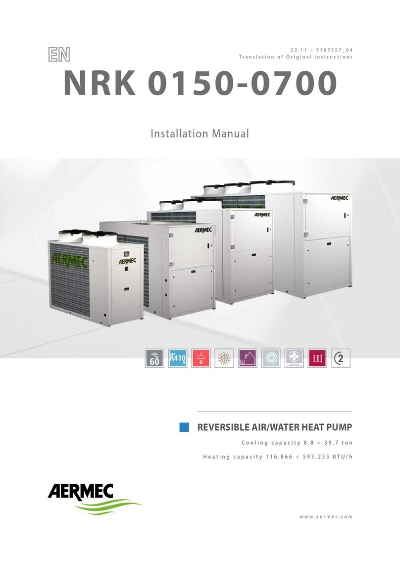
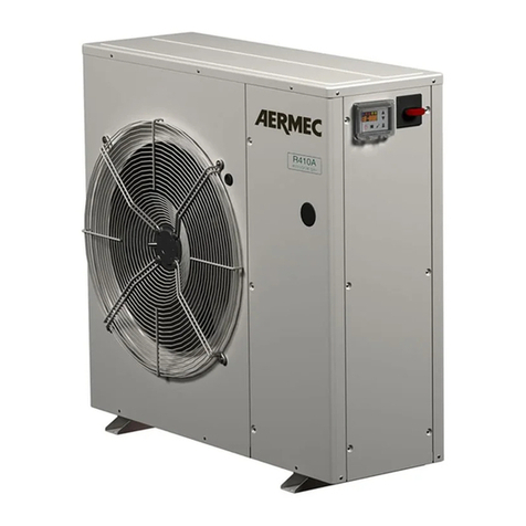
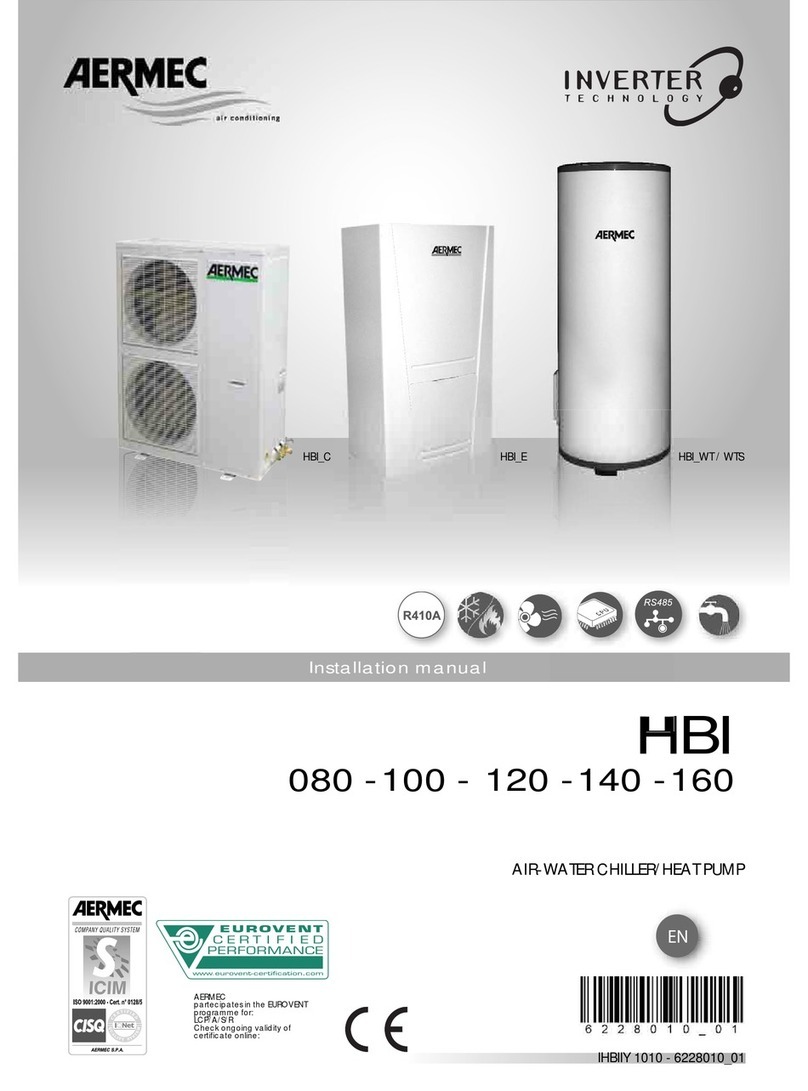
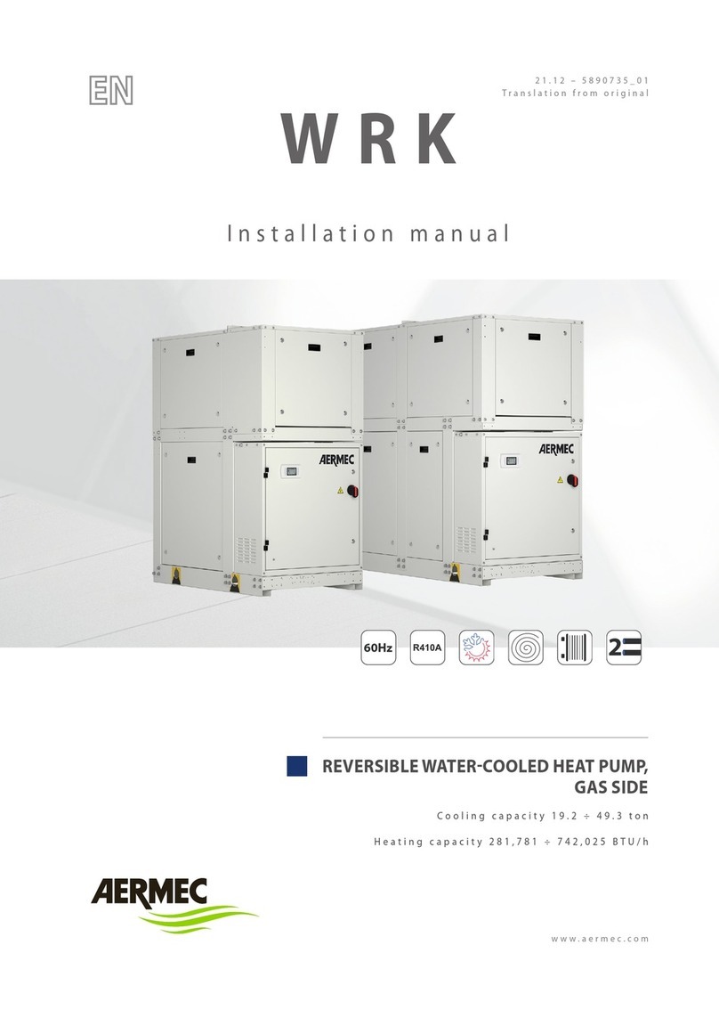
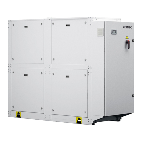
  9. AERMEC CU 31 User manual

AERMEC CU 31 User manual

ISO 9001 - Cert. n° 0128/4
ICUUW
0703
6332311_01
Unità motocondensanti raffreddate ad aria
Air cooled condensing unit
CU
Sostituisce il:
Replace:
6332311 / 0206
MM
MMAA
AANN
NNUU
UUAA
AALL
LLEE
EE
UU
UUNN
NNII
IICC
CCOO
OO
••
••
BB
BBOO
OOOO
OOKK
KKLL
LLEE
EETT
TT
3
II
IINN
NNDD
DDII
IICC
CCEE
EE
••
••
CC
CCOO
OONN
NNTT
TTEE
EENN
NNTT
TTSS
SS
INFORMAZIONI GENERALI
•
GENERAL INFORMATION
5
CARATTERISTICHE
•
FEATURES
Descrizione dell’unità • Unit Description
Scopo della macchina • Purpose of the machine
Versioni disponibili • Versions available
Componenti principali • Main components 6
Descrizione dei componenti • Description of components 7
Organi di regolazione • Controls
Organi di sicurezza e controllo • Safety and control devices
Imballo • Packing
Accessori • Accessories
Tabella compatibilità accessori • Accessory compatibility table 8
Dati tecnici • Technical data 9
Criteri di scelta • Selection
Fattore di correzione della potenza frigorifera • Cooling capacity correction factor 10
Rese frigorifere • Cooling capacities 11
Pressione e potenza sonora • Sound pressure and power level
Campo di funzionamento • Operating limits
Linee frigorifere • Refrigerant lines
Dimensioni batterie • Heating coil dimensions 12
Dati elettrici • Electrical data
Taratura dispositivi di protezione • Protection device settings
Taratura dispositivo DR • DR device settings 13
Prestazioni gruppo di ventilazione • Fan group performance 14
Prestazioni gruppo di ventilazione a portata ridotta • Fan group performance with reduced delivery 16
MISURE DI SICUREZZA
•
SAFETY MEASURES
Usi impropri • Improper uses
Anomalie di funzionamento • Malfunctions
Simboli di sicurezza • Safety symbols 18
INSTALLAZIONE
•
INSTALLATION
Canalizzazioni • Ducting connections
Collegamenti frigoriferi • Refrigerant connections
Collegamenti elettrici • Wiring connections
Messa in funzione • Start up 19
Variazione della velocità del ventilatore • Variation of the fan speed
Montaggio della flangia FRC • Installation of the flange FRC 20
FUNZIONAMENTO
•
OPERATION
Funzionamento del pannello comandi • Remote control panel
Intervento delle sicurezze • Tripping of safety devices 21
CARATTERISTICHE
•
FEATURES
Dati dimensionali • Dimensions 22
Spazi tecnici minimi • Minimum technical space
Dati accessori • Accessories data 24
Circuito frigorifero • Chiller circuit 25
Legenda per schemi elettrici • Wiring diagrams key 26
Schemi elettrici • Wiring diagrams 27
AERMEC S.p.A.
37040 Bevilacqua (VR) Italia – Via Roma, 44
Tel. (0442) 633111
Telefax (0442) 93730 – 93566 CU
modello:
model:
numero di serie:
serial number:
Bevilacqua, 26/03/2007 La Direzione Marketing – Marketing Director
Luigi Zucchi
DICHIARAZIONE DI CONFORMITA'
Noi, firmatari della presente, dichiariamo sotto la nostra esclu-
siva responsabilità che l'insieme in oggetto così definito:
UNITA’ MOTOCONDENSANTE RAFFREDDATA AD ARIA
SERIE CU
risulta :
1. conforme alla Direttiva 97/23/CE ed è stato sottoposto,
con riferimento all'allegato II della direttiva stessa, alla
seguente procedura di valutazione di conformità :
modulo H (grandezze CU da 76 a 157)
con controlli eseguiti mediante ispezioni dall'organismo
notificato CEC via Pisacane 46 Legnano MI, numero distin-
tivo 1131;
2. progettato, prodotto e commercializzato nel rispetto delle
seguenti specifiche tecniche (tutti i modelli) :
Norme armonizzate:
- EN 378: Refrigerating system and heat pumps - Safety
and environmental requirements;
- EN 12735: Copper and copper alloys - Seamless, round
copper tubes for air conditioning and refrigeration;
Altre norme:
- UNI 1285-68: Calcolo di resistenza dei tubi metallici
soggetti a pressione interna;
3.progettato, prodotto e commercializzato in conformità
alle seguenti direttive comunitarie (tutti i modelli) :
- Direttiva macchine 98/37/ CE;
- Direttiva bassa tensione 73/23 CEE;
- Direttiva compatibilità elettromagnetica EMC 89/336 CEE.
È fatto divieto di mettere in servizio la macchina, oggetto della
Dichiarazione, prima che la macchina a cui sarà incorporata od
assiemata sia stata dichiarata conforme alle disposizioni della
Direttiva.
DECLARATION OF CONFORMITY
We declare under our own responsability that the above
equipment described as follows:
AIR COOLED CONDENSING UNIT CU SERIE
complies with following provisions:
1. 97/23/CE Standard , since as per enclosure II, it has
undergone the conformity testing procedure:
H module (sizes: CU from 76 to 157)
with checks carried out by the appointed body CEC via
Pisacane 46 Legnano MI, identity code 1131;
2. designed, manufactured and commercialized in com-
pliance with the following technical specifications (all
models):
Harmonized standards:
-EN 378: Refrigerating system and heat pumps - Safety
and environmental requirements;
-EN 12735: Copper and copper alloys - Seamless, round
copper tubes for air conditioning and refrigeration;
Others:
-UNI 1285-68: calculation of metal tubes resistance to
inside pressure;
3. designed, manufactured and commercialized in com-
pliance with the following EEC Standards (all models):
- Equipment standard 98/37/ EC;
- Low voltage standard 73/23 EEC;
- Electromagnetic compatibility Standard EMC 89/336 EEC.
It is not allowed to operate the appliance object of the
Declaration before the appliance it will incorporated to or
assembled with, is declared in compliance with the provi-
sions of the Directive.
5
II
IINN
NNFF
FFOO
OORR
RRMM
MMAA
AAZZ
ZZII
IIOO
OONN
NNII
II
GG
GGEE
EENN
NNEE
EERR
RRAA
AALL
LLII
II
••
••
GG
GGEE
EENN
NNEE
EERR
RRAA
AALL
LL
II
IINN
NNFF
FFOO
OORR
RRMM
MMAA
AATT
TTII
IIOO
OONN
NN
OSSERVAZIONI
Conservare il manuale in luogo asciutto, per evitare il
deterioramento, per almeno 10 anni per eventuali riferimen-
ti futuri.
Leggere attentamente e completamente tutte le informa-
zioni contenute in questo manuale.
Prestare particolarmente attenzione alle norme d’uso
accompagnate dalle scritte “PERICOLO” o “ATTENZIO-
NE” in quanto, se non osservate, possono causare danno
alla macchina e/o a persone e cose.
Per anomalie non contemplate da questo manuale, interpel-
lare tempestivamente il Servizio Assistenza di zona.
AERMEC S.p.A. declina ogni responsabilità per qualsiasi
danno dovuto ad un uso improprio della macchina, ad una
lettura parziale o superficiale delle informazioni contenute
in questo manuale.
Il numero di pagine di questo manuale è: 32.
REMARKS
Store the manual in a dry location to avoid deterioration, as
they must be kept for at least 10 years for any future referen-
ce.
All the information in this manual must be carefully read
and understood.
Pay particular attention to the operating standards with
“DANGER” or “WARNING” signals as their disrespect can
cause damage to the machine and/or persons or objects.
If any malfunctions are not included in this manual, contact
the local Aftersales Service immediately.
AERMEC S.p.A. declines all responsibility for any damage
whatsoever caused by improper use of the machine, and a
partial or superficial acquaintance with the information con-
tained in this manual.
This manual has 32 pages.
6
CC
CCAA
AARR
RRAA
AATT
TTTT
TTEE
EERR
RRII
IISS
SSTT
TTII
IICC
CCHH
HHEE
EE
••
••
FF
FFEE
EEAA
AATT
TTUU
UURR
RREE
EESS
SS
DESCRIZIONE DELL’UNITÀ
SCOPO DELLA MACCHINA
Le unità motocondensanti della serie CU sono state realiz-
zate per soddisfare le esigenze delle medie e piccole utenze
per usi civili ed commerciali. Le unità sono caratterizzate
da un funzionamento estremamente silenzioso e da un’ele-
vata efficienza ed affidabilità, grazie all’adozione di compo-
nenti di elevate prestazioni.
Completamente assemblate in fabbrica e singolarmente
testate, le unità garantiscono semplicità d’installazione e
facile ispezionabilità dei componenti.
VERSIONI DISPONIBILI
Grandezze disponibili con gas R407C:
CU 317
Grandezze disponibili con gas R22:
CU 31 - 51 - 76 - 101 - 151
UNIT DESCRIPTION
PURPOSE OF THE MACHINE
The CU series of condensing units have been designed to
satisfy the needs of small to medium sized civil and indu-
strial installations. The units feature extremely quite opera-
tion and high efficiency and reliability, attained by the
implementation of highly qualified components.
Completely factory assembled and individually tested, the
units guarantee simple and easy installation and component
inspection.
VERSIONS AVAILABLE
Sizes available with gas R407C:
CU 317
Sizes available with gas R22:
CU 31 - 51 - 76 - 101 - 151
1
2
3
4
5
6
7
8
1Pannello comandi • Control panel
2Gruppo ventilante • Fan group
3Scambiatore lato aria • Air side exchanger
4Serbatoio di liquido • Liquid tank
5Compressore • Compressor
6Interruttore generale • Main switch
7Quadro elettrico • Switchboard
8Struttura portante • Frame
COMPONENTI PRINCIPALI • MAIN COMPONENTS
CU 51
7
CC
CCAA
AARR
RRAA
AATT
TTTT
TTEE
EERR
RRII
IISS
SSTT
TTII
IICC
CCHH
HHEE
EE
••
••
FF
FFEE
EEAA
AATT
TTUU
UURR
RREE
EESS
SS
DESCRIZIONE DEI COMPONENTI
1 PANNELLO COMANDI REMOTO
Consente di eseguire a distanza le seguenti operazioni:
– accensione e spegnimento dell’unità ON / OFF (visualiz-
zazione tramite interruttore luminoso);
– riassunto allarmi mediante accensione di una spia;
– pulsante di avviamento e riarmo.
Il collegamento fra l’unità ed il pannello viene eseguito
mediante cavo a 6 poli di sezione: 1 mm2(max. 50 m).
2 GRUPPO VENTILANTE
Costituito da due ventilatori centrifughi a doppia aspirazio-
ne e pale avanti, bilanciati staticamente e dinamicamente,
azionati da motori elettrici trifase accoppiati mediante cin-
ghie trapezoidali e pulegge regolabili, consente l'installazio-
ne con mandata dell'aria canalizzata.
Per adeguare le prestazioni del gruppo di ventilazione a
specifiche esigenze sono disponibili tipi diversi di motori e
pulegge.
Il gruppo ventilante è supportato da ammortizzatori in
gomma ed equipaggiato di rete di protezione contro contatti
accidentali dal lato della bocca di mandata.
3 SCAMBIATORE LATO ARIA
Realizzata con tubi di rame rigato internamente ed alette in
alluminio di tipo turbolenziato (di tipo corrugato sul model-
lo CU 151) bloccate mediante espansione meccanica dei
tubi. Ha capacità sufficiente per contenere l'intera carica di
refrigerante del circuito.
La batteria è fornita di serie di rete metallica di protezione.
4 SERBATOIO DI LIQUIDO
Posto in uscita dal condensatore, è dotato di rubinetto
d’intercettazione.
5 COMPRESSORE
R22- Di tipo ermetico ad elevata efficienza, montato su sup-
porti elastici antivibranti, azionato da un motore elettrico a
due poli con protezione termica interna.
Il compressore, dotato di serie di resistenza di riscaldamen-
to dell’olio, è isolato acusticamente con materiale fo-
noassorbente.
R407C- SCROLL
6 INTERRUTTORE GENERALE
È costituito da un interruttore con maniglia bloccaporta
installato di serie sul quadro elettrico per tutti i modelli.
7 QUADRO ELETTRICO
Contiene la sezione di potenza e la gestione dei controlli e
delle sicurezze. È conforme allo Standard IP 44.
8 MOBILE DI COPERTURA
Realizzato in lamiera di acciaio zincato verniciata a caldo
con polveri poliuretaniche dopo trattamento di passivazio-
ne, è in grado di resistere a lungo all’azione degli agenti
atmosferici.
- PRESSOSTATO DI ALTA
A taratura fissa, posto sul lato ad alta pressione del circuito
frigorifero, arresta il funzionamento del compressore in caso
di pressioni anomale di lavoro.
- PRESSOSTATO DI BASSA
A taratura fissa, posto sul lato ad bassa pressione del circui-
to frigorifero, arresta il funzionamento del compressore in
caso di pressioni anomale di lavoro.
- RUBINETTI
Consentono d’intercettare il gas refrigerante in caso di
manutenzione straordinaria.
- SILENZIATORE
Posto a monte del compressore, serve ad attenuare le vibra-
zioni causate dal moto del gas.
COMPONENT DESCRIPTION
1 REMOTE CONTROL PANEL
For remote control of the following operations:
– unit ON / OFF (luminous switch display);
– summation of alarms by illumination of lamp;
– start and reset button.
The connection between the unit and the panel is made by
means of a 6 pole cable with a section of: 1 mm2(max. 50
m).
2 FAN SECTION
Double intake centrifugal fans with forward blades, statically
and dinamically balanced, belt driven by threephase electric
motors with variable diameter pulleys to perform air duc-
ting.
To suit the fan section performances to specific require-
ments there is a range of motors and pulleys.
The ventilation section is mounted on rubber dampers and
provided with a protection grill on the air delivery.
3 AIR SIDE HEAT EXCHANGER
Waffle aluminum slit fins (corrugated fins for model CU
151) and mechanically expanded inner grooved copper
tubes .
The exchanger can hold the whole refrigerant charge and is
provided with a protection grill.
4 LIQUID TANK
Positioned to the condenser outlet, it is provided with inter-
ception cock.
5 COMPRESSOR
R22 - Hermetic, high efficiency type, mounted on anti-vibra-
tion pads, it is driven by a two pole electric motor with inner
amperometric protection.
The compressor is standard equipped with cranckase heater
and is sound insulated.
R407C- SCROLL.
6 MAIN SWITCH
It includes a switch with door handle lock and is standard
installed inside the electric board of all models.
7 SWITCHBOARD
It contains the power section and the management of the
controls and safeties. It has conform to IP 44.
8 CHANNEL FRAME
It is made of long life galvanized steel panels hot painted
with polyurethane powder after passivation.
- HIGH PRESSURE SWITCH
With set calibration, mounted on the high pressure side of
the refrigerant circuit. It blocks operation of the compressor
at abnormal working pressures.
- LOW PRESSURE SWITCH
With set calibration, mounted on the low pressure side of
the refrigerant circuit. It blocks operation of the compressor
at abnormal working pressures.
- COCKS
To cut off the refrigerant gas during repair work.
- MUFFLER
Located upstream the compressor, it dampens the vibrations
originated by the gas flow.
8
CC
CCAA
AARR
RRAA
AATT
TTTT
TTEE
EERR
RRII
IISS
SSTT
TTII
IICC
CCHH
HHEE
EE
••
••
FF
FFEE
EEAA
AATT
TTUU
UURR
RREE
EESS
SS
ORGANI DI REGOLAZIONE
GESTIONE COMPRESSORE (CP)
Il compressore rimane sempre e comunque fermo per almeno
un minuto dopo lo spegnimento e devono inoltre essere tra-
scorsi almeno sei minuti dall’ultima accensione.
ORGANI DI SICUREZZA E CONTROLLO
- interruttore generale bloccaporta
- magnetotermico protezione compressore
- magnetotermico protezione ausiliario
- magnetotermico protezione ventilatori
- teleruttori alimentazione compressore
- teleruttori alimentazione ventilatori
- pressostati di bassa e alta pressione
- pannello comandi remoto composto da:
commutatore ON/OFF;
commutatore Reset;
segnalazione riassunto allarmi.
IMBALLO
Le unità vengono spedite con imballo standard costituito da
un basamento in legno e da un rivestimento in polietilene
estendibile.
L'imballo standard può essere completato da una gabbia o
cassa in legno.
Il pannello comandi è posizionato all'interno del quadro
elettrico.
ACCESSORI
DR – DISPOSITIVO PER BASSE TEMPERATURE
Consente un corretto funzionamento in raffreddamento con
temperature esterne inferiori a 20 °C e fino a –10 °C.
È costituito da una sonda montata sul lato di alta pressione
e da un insieme trasduttore-operatore che comanda una ser-
randa di regolazione posta sulla mandata dell'aria (Tab G).
Il dispositivo è alimentato a 24V; pertanto bisogna predi-
sporre un trasformatore da 25VA, primario 230V e seconda-
rio 24V.
Se si utilizza l'accessorio «DR» non si può utilizzare la
flangia «FRC».
FRC – FLANGIA PER CANALI
Realizzata in lamiera di acciaio zincata e verniciata, per-
mette il collegamento ai canali di aspirazione e mandata
dell'aria.
Viene fissata all'unità mediante viti autofilettanti.
Se si utilizza la flangia «FRC» non si può utilizzare l'acces-
sorio «DR».
CONTROLS
COMPRESSOR MANAGEMENT (CP)
The compressor always remains off for at least one minute
after it has been turned off; at least six minutes must pass
after the last start-up.
SAFETY AND CONTROL DEVICES
- general door lock switch
- compressor circuit breaker
- circuit breaker for auxiliary circuit
- circuit breaker for fans
- compressor starters
- fan starters
- low and high pressure switches
- remote control panel comprising:
ON/OFF switch;
Reset changeover switch;
Summation alarm signal.
PACKING
The units are standard conditioned for shipment in wooden
pallets, wrapped in a nylon coating.
Upon request, they can be wooden crated or cased.
The control panel is shipped inside the electric board.
ACCESSORIES
DR – LOW AMBIENT TEMPERATURE OPERATION DEVICE
It allows a proper operation with ambient temperatures of
20 °C down to –10 °C.
It is composed of a sensor fitted on the high pressure side
and a transducer-operator system that controls a regulation
damper mounted on the air discharge (Tab G). The device
is fed at 24V. Therefore, use a 25VA transformer, with 230V
primary circuit and 24V secondary circuit.
The «DR» louver cannot be installed when the «FRC» duct
flange is used.
FRC – DUCT FLANGE
It is made of painted galvanized steel panels to be screwed
to the unit when connection to an air delivery and return
duct system is required.
It is fixed to the outdoor unit by self-tapping screws.
The «FRC» duct flange cannot be installed when the «DR»
louver is used.
Accessori disponibili – Available accessories
Mod. CU 317 31 51 71 101 151
DR 32 ✔✔
DR 52 ✔
DR 77 ✔
DR 102 ✔
DR 152 ✔
FRC 31 ✔✔
FRC 51 ✔
FRC 71 ✔
FRC 101 ✔
FRC 151 ✔
TABELLA DI COMPATIBILITÀ DEGLI ACCESSORI • ACCESSORIES COMPATIBILITY TABLE
9
CC
CCAA
AARR
RRAA
AATT
TTTT
TTEE
EERR
RRII
IISS
SSTT
TTII
IICC
CCHH
HHEE
EE
••
••
FF
FFEE
EEAA
AATT
TTUU
UURR
RREE
EESS
SS
DATI TECNICI • TECHNICAL DATA
Tensione di alimentazione: 230 V - 3 - 50 Hz; 400 V - 3+N - 50 Hz (±10%).
Le prestazioni sono riferite alle seguenti condizioni:
temperatura aria esterna 35 °C;
temperatura di evaporazione 5 °C.
Power supply: 230 V - 3 - 50 Hz; 400 V - 3+N - 50 Hz (±10%).
Performances refer to following conditions:
ambient temperature 35 °C;
evaporation temperature 5 °C.
Mod. CU 317 31 51 76 101 151
Gas R407C [ R22 ]
Potenzialità frigorifera kW 9,7 8,95 14,7 23,25 31,4 40,35
Cooling capacity
Potenza assorbita totale kW 3,75 3,75 5,56 8,7 11,36 15,33
Total input power
E.E.R. W/W 2,59 2,17 2,34 2,48 2,39 2,27
Ventilatori • Fans n° 222222
Potenza motore n° x kW 1 x 0,75 1 x 0,75 1 x 1,1 1 x 1,5 2 x 1,1 2 x 1,5
Motor power
Portata aria nominale m3/h 3.500 3.500 6.000 8.600 12.000 16.000
Nominal air flow
Velocità ventilatore ( nominale ) g/m • rpm 930 930 880 740 625 590
Fan speed ( nominal )
Massima pressione statica disponibile Pa 108 108 108 108 88,3 117,7
Max. available static pressure
Potenza sonora •
Batteria Superficie • Surface m20,385 0,385 0,578 0,875 1,125 1,312
Coil Ranghi • Row n° 333333
Attacchi ø (Gas) (10 m) 15,88 18 22 28 28 35
frigoriferi
Cooling ø (Liquido • Liquid) (10 m) 9,52 9,52 12,7 16 16 16
connections
Compressore • Compressor tipo • type SCROLL [ Alternativo • Reciprocating ]
Assorbimento totale A (230 V) 13,7 12 18,5 27,2 37 47,3
Total input current A (400 V) 7 6,9 10,7 15,7 21 27,3
Corrente di spunto A (230 V) 98 75,5 128 148 209 258
Peak current A (400 V) 45 45,5 69,5 91,5 127,5 159
Dimensioni Altezza • Height mm 975 975 975 1200 1310 1310
Dimensions Larghezza • Width mm 950 950 1300 1500 1750 2000
Profondità • Depth mm 600 600 600 700 850 850
Peso netto • Net weight kg 145 152 200 294 391 462
10
CC
CCAA
AARR
RRAA
AATT
TTTT
TTEE
EERR
RRII
IISS
SSTT
TTII
IICC
CCHH
HHEE
EE
••
••
FF
FFEE
EEAA
AATT
TTUU
UURR
RREE
EESS
SS
TAV 1 FATTORE DI CORREZIONE DELLA POTENZA FRIGORIFERA
COOLING CAPACITY CORRECTION FACTOR
CRITERI DI SCELTA
Le tabelle da A ad Q riportano tutti i dati necessari per una
corretta scelta dell'unità. Le potenze frigorifere devono esse-
re corrette secondo quanto indicato in TAV. 1.
Le potenze assorbite sono quelle totali (compressore e ven-
tilatori).
Le unità sono previste per funzionare correttamente in fase
di raffreddamento fino ad una temperatura esterna minima
di 20 °C.
Per temperature esterne minori di 20 °C sarà necessario
prevedere l'inserimento del dispositivo di controllo « DR ».
SELECTION
Tables A to Q give all the data needed for a precise selec-
tion of the unit. The cooling capacities must be corrected
according to the factors given in TAV. 1.
The absorbed powers are total (compressor and fans).
The units are designed for correct operation in cooling at a
minimum ambient temperature of 20 °C.
For ambient temperatures lower than 20 °C the « DR » con-
trol must be installed.
0,96
0,97
0,98
0,99
1
1,01
1,02
5 1015202530 L (m)
K 1,03
0,96
0,97
0,98
0,99
1
1,01
1,02
5 1015202530 L (m)
K 1,03
CU 31 – CU 51 CU 76 – CU 101 – CU 151
Per linee frigorifere eseguite rispettando le specifiche ripor-
tate nella tabella C, la potenza frigorifera (vedi TAB. A) va
corretta, in funzione della lunghezza delle linee ( L), molti-
plicandola per il coefficiente K, riportato nel diagramma a
fianco.
La potenza assorbita non è influenzata in modo apprezza-
bile.
For refrigerant lines complying with the specification given
in table C the cooling capacity (see TAB. A) must be cor-
rected, according to the line length ( L), multiplying by
coefficient K, given in the chart to the side.
The input power is not significantly affected.
11
CC
CCAA
AARR
RRAA
AATT
TTTT
TTEE
EERR
RRII
IISS
SSTT
TTII
IICC
CCHH
HHEE
EE
••
••
FF
FFEE
EEAA
AATT
TTUU
UURR
RREE
EESS
SS
TAB A POTENZA FRIGORIFERA TOTALE ED ASSORBIMENTO ELETTRICO TOTALE
COOLING CAPACITY AND TOTAL INPUT POWER
T a T ev Mod. CU 31 CU 51 CU 76 CU 101 CU 151
0Pf 9,4 14,8 24,5 32,4 42
Pa 3,2 4,3 7,1 8,9 12,2
2,5 Pf 10,2 16,2 26,7 35,4 45,5
Pa 3,3 4,5 7,3 9,3 12,6
20 5 Pf 11,1 17,7 29 38,4 49
Pa 3,4 4,7 7,5 9,7 13
7,5 Pf 12 19,2 31,3 41,4 52,6
Pa 3,6 4,9 7,7 10 13,7
10 Pf 13 20,6 33,6 44,4 57
Pa 3,7 5,1 7,8 10,4 13,8
0Pf 8,7 14 22,8 30,4 39
Pa 3,3 4,6 7,5 9,5 13
2,5 Pf 9,5 15,4 24,9 33,2 42,6
Pa 3,4 4,8 7,7 9,9 13,4
25 5 Pf 10,4 16,7 27 36,1 46,2
Pa 3,5 5 7,9 10,3 13,9
7,5 Pf 11,2 18,1 29,2 39 49,9
Pa 3,7 5,2 8,1 10,7 14,4
10 Pf 12,1 19,5 31,3 41,8 53,5
Pa 3,8 5,4 8,3 11,1 14,8
0Pf 8,1 13,2 21,1 28,4 36,5
Pa 3,4 4,9 7,8 10 13,6
2,5 Pf 8,9 14,4 23,1 31,1 39,9
Pa 3,5 5,1 8,1 10,4 14,1
30 5 Pf 9,7 15,7 25,1 33,8 43,3
Pa 3,7 5,3 8,3 10,8 14,6
7,5 Pf 10,5 17 27,1 36,4 46,7
Pa 3,8 5,5 8,5 11,3 15,2
10 Pf 11,3 18,3 29,2 39,1 50
Pa 4 5,7 8,8 11,7 15,7
T a = Temperatura aria ingresso condensatore (°C b.s.)
T ev = Temperatura di evaporazione (°C)
Pf = Potenzialità frigorifera (kW)
Pa = Potenza assorbita elettrica totale (kW)
T a = Condenser inlet air temperature (°C d.b.)
T ev = Evaporating temperature (°C)
Pf = Cooling capacity (kW)
Pa = Total power consumption (kW)
T a T ev Mod. CU 31 CU 51 CU 76 CU 101 CU 151
0Pf 7,5 12,3 19,5 26,4 34
Pa 3,5 5,1 8,2 10,5 14,2
2,5 Pf 8,2 13,5 21,4 28,9 37,2
Pa 3,6 5,3 8,4 10,9 14,8
35 5 Pf 9 14,7 23,3 31,4 40,4
Pa 3,8 5,6 8,7 11,4 15,3
7,5 Pf 9,7 15,9 25,2 33,9 43,6
Pa 3,9 5,8 9 11,8 15,9
10 Pf 10,5 17,1 27,2 36,3 46,7
Pa 4,1 6 9,3 12,3 16,5
0Pf 7 11,5 18 24,5 31,5
Pa 3,5 5,3 8,5 10,9 14,8
2,5 Pf 7,6 12,6 19,7 26,8 34,5
Pa 3,7 5,6 8,8 11,4 15,4
40 5 Pf 8,3 13,7 21,6 29,1 37,5
Pa 3,9 5,8 9,2 11,9 16
7,5 Pf 9 14,8 23,4 31,3 40,5
Pa 4 6,1 9,5 12,4 16,6
10 Pf 9,7 15,9 25,2 33,5 43,5
Pa 4,2 6,3 9,9 12,9 17,3
0Pf 6,4 10,6 16,5 22,4 29,1
Pa 3,6 5,5 8,8 11,4 15,4
2,5 Pf 7 11,6 18,2 24,6 31,9
Pa 3,8 5,7 9,2 11,9 16
45 5 Pf 7,6 12,7 19,9 26,7 34,7
Pa 4 6 9,6 12,4 16,6
7,5 Pf 8,3 14,3 21,6 30 39
Pa 4,2 6,2 10,1 12,7 17
10 Pf 9,4 – 24,3 32,2 41,8
Pa 4,3 – 10,2 13,2 17,7
Temperatura esterna aria max 43 °C
Ambient air temperature max 43 °C
I valori estremi riportati nella TAB. A sono da considerare
come limiti di funzionamento; è quindi consentita l’interpo-
lazione ma non l’estrapolazione.
The range of values given in TAB. A must be considered as
operating limits; therefore extrapolation is not valid or per-
mitted.
12
CC
CCAA
AARR
RRAA
AATT
TTTT
TTEE
EERR
RRII
IISS
SSTT
TTII
IICC
CCHH
HHEE
EE
••
••
FF
FFEE
EEAA
AATT
TTUU
UURR
RREE
EESS
SS
TAB B PRESSIONE E POTENZA SONORA espressa in dB(A)
SOUND PRESSURE AND POWER LEVEL rated in dB(A)
Pressione sonora* Potenza sonora per frequenza centrale di banda (Hz) globale
Sound pressure* Sound power band middle frequency (Hz) total
Mod. 125 250 500 1.000 2.000 4.000 8.000
dB(A) dB dB dB dB dB dB dB dB dB (A)
31 70,5 A 87,5 78,5 75 73 70,5 67 60,5 88,5 79
B 85,5 76,5 73 71 68,5 65 58,5 86,5 77
51 72 A 86 80,5 76,5 76 72 68,5 59,5 88 80,5
B 84 78,5 74,5 74 70 66,5 57,5 86 78,5
76 74 A 90,5 78,5 80 75,5 75 71 61,5 91,5 82,5
B 88,5 76,5 78 73,5 73 69 59,5 89,5 80,5
101 75,5 A 94 80 81 77,5 76 72 62 94,5 84
B 92 78 79 75,5 74 70 60 92,5 82
151 74 A 86,5 78 79,5 77,5 75 71,5 59 88,5 82,5
B 84,5 76 77,5 75,5 73 69,5 57 86,5 80,5
I valori sono riferiti alle condizioni nominali di funzionamento in raffreddamento.
* = Pressione sonora in camera semiriverberante di volume 85 m3e con tempo di riverberazione Tr = 0,5 s.
Given data refer to nominal cooling operation working conditions.
* = sound pressure in a 85 m3semi-reverberating room and with a reverberating time Tr = 0,5 sec.
A = potenza sonora emessa • sound power level
B = potenza sonora immessa nel canale di mandata • sound power level emitted in the air duct.
TAB C LINEE FRIGORIFERE • REFRIGERANT LINES
Lunghezza linea Linea gas Linea liquido Gas per metro di linea H max
Mod. Line lenght Gas line Liquid line Gas per meter of line
m Ø mm Ø mm g m
0 ÷ 10 16 9,52 53 5
CU 317 11 ÷ 30 (max) 18 9,52 53 8
0 ÷ 5 16 9,52 40 5
CU 31 5 ÷ 13 18 9,52 54 8
13 ÷ 20 (max) 18 12,7 110 8
0 ÷ 5 18 9,52 40 5
CU 51 5 ÷ 13 22 12,7 110 8
13 ÷ 20 (max) 22 12,7 110 13
0 ÷ 15 28 16 190
CU 76 15 ÷ 30 (max) 35 18 235 15
0 ÷ 15 28 16 190
CU 101 15 ÷ 30 (max) 35 18 235 15
0 ÷ 15 35 16 190
CU 151 15 ÷ 30 (max) 42 18 235 15
DATI DI PROGETTO • DESIGN DATA R407C
Lato in alta pressione Lato bassa pressione
High pressure side Low pressure side
Pressione massima ammissibile • Max pressure allowable [bar] 28 -
Temperatura mass. ammissibile • Max temp. allowable [°C] 120 52
Temperatura min. ammissibile • Min. temp. allowable [°C] -10 -16
TAB D DIMENSIONI BATTERIE • HEATING COIL DIMENSIONS
Mod. CU 31 51 76 101 151
Sezione frontale • Front surface area (m2) 0,39 0,58 0,88 1,13 1,31
Ranghi • Rows (n°) 33333
13
CC
CCAA
AARR
RRAA
AATT
TTTT
TTEE
EERR
RRII
IISS
SSTT
TTII
IICC
CCHH
HHEE
EE
••
••
FF
FFEE
EEAA
AATT
TTUU
UURR
RREE
EESS
SS
TAB E DATI ELETTRICI • ELECTRICAL DATA
Mod. CU 31 51 76 101 151
Cavi di alimentazione Ø A 230 V mm24 6 10 16 25
Power line 400 V mm22,5 4 6 10 16
Fusibile di linea (ritardato) F230 V A 25 35 50 63 80
Delayed fuses 400 V A 16 25 35 40 50
Interruttore di linea IL 230 V A 25 40 63 63 100
Line switch 400 V A 16 25 40 40 63
Resistenza carter • Crankcase heater W 4035353535
TAB F TARATURA DISPOSITIVI DI PROTEZIONE • PROTECTION DEVICE SETTINGS
Mod. CU 31 51 76 101 151
Protezione termica interna compressore A°C 110 100 ÷110 100 ÷110 100 ÷110 100 ÷110
Compressor inner thermal protection B°C 69 69 69 69 69
❄❄ Controllo tensione alimentazione – – – ±13% ±13%
Power supply voltage control
Magnetotermico circuito ausiliario A44444
Auxiliary circuit magnetothermic protection
Magnetotermico ventilatore 400 V A 2,4 3,2 4,1 2 x 3,5 2 x 4,5
Fan magnetothermic protection 230 V A 4,1 5,6 7,1 2 x 6,0 2 x 7,7
Magnetotermico compressore 400 V A 10 16 25 32 40
Compressor magnetothermic protection 230 V A 16 32 40 50 63
Pressostato alta pressione AkPa 2550 ± 69 2550 ± 69 2550 ± 69 2550 ± 69 2550 ± 69
High pressure switch BkPa 1795 ± 69 1795 ± 69 1795 ± 69 1795 ± 69 1795 ± 69
Pressostato bassa pressione AkPa 59 ± 14 59 ± 14 59 ± 14 59 ± 14 59 ± 14
Low pressure switch BkPa 157 ± 21 157 ± 21 157 ± 21 157 ± 21 157 ± 21
A= intervento • cut - out B= riarmo • cut - in.
❄❄ Variazione percentuale rispetto alla tensione nominale (230 o 400 V)
Percentage variation from nominal feeding voltage (230 or 400 V).
TAB G TARATURA DISPOSITIVO DR • DR DEVICE SETTINGS
valore di taratura del pressostato serranda completamente aperta serranda completamente chiusa
pressure switch calibration louver fully open louver fully closed
1570 ± 196 kPa 1766 kPa 1373 kPa
14
CC
CCAA
AARR
RRAA
AATT
TTTT
TTEE
EERR
RRII
IISS
SSTT
TTII
IICC
CCHH
HHEE
EE
••
••
FF
FFEE
EEAA
AATT
TTUU
UURR
RREE
EESS
SS
Le prestazioni, riferite alla Tab. H, sono relative al gruppo di ventilazione standard.
Le prestazioni relative alle Tab. I e L vengono ottenute con pulegge di diverso diametro e motori di potenza maggiora-
ta, disponibili come accessorio. Le caratteristiche del gruppo di ventilazione potenziato, da richiedere in fase d’ordine,
sono illustrate in Tab. M.
The performances, given in Tab. H refer to the standard fan section.
The performances in Tab. I and L are obtained with pulleys of different diameters and uprated motors, available as
accessories. The characteristics of the uprated fan section, to be requested at the time of order, are shown in Tab. M.
PRESTAZIONI GRUPPO DI VENTILAZIONE • FAN GROUP PERFORMANCE
Gruppo di ventilazione standard • Standard fan group TAB. H
Mod. CU 31 51 71 101 151
Qa = 3500 m3/h Qa = 6000 m3/h Qa = 8600 m3/h Qa = 12000 m3/h Qa = 16000 m3/h
PSU RPM Pe RPM Pe RPM Pe RPM Pe RPM Pe
(Pa) (n°/1’) (W) (n°/1’) (W) (n°/1’) (W) (n°/1’) (W) (n°/1’) (W)
0 920 490 900 850 745 1080 610 1750 530 2250
20 965 525 935 920 780 1160 640 1890 555 2430
40 1010 560 970 990 815 1245 665 2045 580 2610
60 1055 600 1005 1065 845 1330 685 2190 605 2795
80 1100 640 1040 1140 875 1415 710 2345 630 2980
100 1145 680 1085 1215 905 1505 730 2500 – –
120 1190 720 – – 935 1595 ––––
Gruppo di ventilazione optional • Optional fan group TAB. I
Mod. CU 31 51 71 101 151
Qa = 3500 m3/h Qa = 6000 m3/h Qa = 8600 m3/h Qa = 12000 m3/h Qa = 16000 m3/h
PSU RPM Pe RPM Pe RPM Pe RPM Pe RPM Pe
(Pa) (n°/1’) (W) (n°/1’) (W) (n°/1’) (W) (n°/1’) (W) (n°/1’) (W)
100 ––––––––6403170
120 – – 1115 1280 – – 760 2660 660 3360
140 1240 795 1150 1355 970 1685 780 2820 680 3560
160 1280 850 1185 1430 1000 1780 800 2980 700 3755
180 1320 900 1220 1495 1030 1870 825 3145 730 3960
200 1360 955 1250 1570 1060 1965 850 3310 750 4160
220 1400 1010 1285 1650 1090 2060 875 3480 770 4370
240 1440 1070 1320 1730 1120 2165 – – 790 4580
260 ––––1150 2265 – – 800 4740
280 ––––1175 2365 ––––
Gruppo di ventilazione optional • Optional fan group TAB. L
Mod. CU 31 51 71 101 151
Qa = 3500 m3/h Qa = 6000 m3/h Qa = 8600 m3/h Qa = 12000 m3/h Qa = 16000 m3/h
PSU RPM Pe RPM Pe RPM Pe RPM Pe RPM Pe
(Pa) (n°/1’) (W) (n°/1’) (W) (n°/1’) (W) (n°/1’) (W) (n°/1’) (W)
260 1470 1120 ––––––––
280 1510 1180 ––––––––
300 1540 1230 ––––––––
320 1575 1290 ––––––––
340 1610 1350 ––––––––
360 1640 1430 ––––––––
PSU = pressione statica utile • useful static pressure.
RPM = numero di giri del ventilatore • fan speed.
Pe = potenza elettrica assorbita dal motore • motor input current.
15
CC
CCAA
AARR
RRAA
AATT
TTTT
TTEE
EERR
RRII
IISS
SSTT
TTII
IICC
CCHH
HHEE
EE
••
••
FF
FFEE
EEAA
AATT
TTUU
UURR
RREE
EESS
SS
PRESTAZIONI GRUPPO DI VENTILAZIONE • FAN GROUP PERFORMANCE
CAMPO DI UTILIZZO • FIELD OF USE TAB. M
Gruppo di ventilazione • Fan group Ø 1 Ø 2 Pn
Standard CU 31 75 - 100 118 0,75
CU 51 75 - 100 130 1,1
Prestazioni di Tab. H CU 71 95 - 120 170 1,5
Performances of Tab. H CU 101 95 - 120 150 2 x 1,1
CU 151 95 - 120 180 2 x 1,5
Optional CU 31 75 - 100 100 0,75
CU 51 95 - 120 120 1,5
Prestazioni di Tab. I CU 71 95 - 120 140 2,2
Performances of Tab. I CU 101 95 - 120 130 2 x 1,5
CU 151 95 - 120 210 2 x 2,2
Optional CU 31 75 - 100 85 1,1
CU 51 –––
Prestazioni di Tab. L CU 71 –––
Performances of Tab. L CU 101 –––
CU 151 –––
Ø 1= Diametro della puleggia variabile montata sull’albero del motore
Diameter of the variable pulley mounted on the driving shaft
Ø 2= Diametro della puleggia fissa montata sull’albero del ventilatore
Diameter of the fixed pulley mounted on the driving shaft
P n = Potenza nominale del motore elettrico (kW) • Nominal power of electric motor (kW)
Le versioni CU 101 e CU 151 con motore standard e la versione CU 101 con motore potenziato utilizzano motori a 6 poli.
Le restanti versioni utilizzano motori a 4 poli.
The models CU 101 and CU 151 with standard motors and model CU 101 with uprated motor have 6 pole motors fitted.
The remaining models have a 4 pole motor.
La taratura del numero di giri viene eseguita agendo sulla puleggia variabile come da Fig. 1.
Si precisa che, all’atto della spedizione, le pulegge variabili sono regolate in modo di aver portata d’aria nominale e pre-
valenza nulla.
The calibration of the number of revolutions is carried by acting on the variable pulley as seen in Fig. 1.
The units are normally shipped with pulley set to obtain the nominal flow rate with no static pressure.
16
CC
CCAA
AARR
RRAA
AATT
TTTT
TTEE
EERR
RRII
IISS
SSTT
TTII
IICC
CCHH
HHEE
EE
••
••
FF
FFEE
EEAA
AATT
TTUU
UURR
RREE
EESS
SS
PRESTAZIONI GRUPPO DI VENTILAZIONE A PORTATA RIDOTTA
FAN GROUP PERFORMANCE WITH REDUCED DELIVERY
Gruppo di ventilazione standard • Standard fan group TAB. N
Mod. CU 31 51 71 101 151
Qa = 2800 m3/h Qa = 4800 m3/h Qa = 6880 m3/h Qa = 9600 m3/h Qa = 12800 m3/h
PSU RPM Pe RPM Pe RPM Pe RPM Pe RPM Pe
(Pa) (n°/1’) (W) (n°/1’) (W) (n°/1’) (W) (n°/1’) (W) (n°/1’) (W)
0 730 235 725 445 585 555 485 890 430 1150
20 795 270 770 500 625 625 520 1005 460 1295
40 855 300 815 560 665 695 550 1125 480 1440
60 910 350 860 620 705 760 585 1245 510 1590
80 – – 905 680 740 835 615 1375 – –
100 – – 940 740 – – 645 1505 – –
Gruppo di ventilazione optional • Optional fan group TAB. O
Mod. CU 31 51 71 101 151
Qa = 2800 m3/h Qa = 4800 m3/h Qa = 6880 m3/h Qa = 9600 m3/h Qa = 12800 m3/h
PSU RPM Pe RPM Pe RPM Pe RPM Pe RPM Pe
(Pa) (n°/1’) (W) (n°/1’) (W) (n°/1’) (W) (n°/1’) (W) (n°/1’) (W)
80 965390––––––5351745
100 1020 430 – – 780 905 – – 560 1905
120 1070 475 990 805 820 985 675 1635 580 2065
140 1120 515 1030 870 855 1060 700 1765 600 2230
160 1165 565 1070 935 890 1140 725 1905 620 2395
180 1210 600 1110 1000 925 1220 750 2040 640 2570
200 1255 655 1145 1065 – – 790 2180 660 2745
220 1285 700 1185 1130 ––––––
240 – – 1220 1200 ––––––
260 – – 1255 1265 ––––––
280 – – 1280 1330 ––––––
Gruppo di ventilazione optional • Optional fan group TAB. P
Mod. CU 31 51 71 101 151
Qa = 2800 m3/h Qa = 4800 m3/h Qa = 6880 m3/h Qa = 9600 m3/h Qa = 12800 m3/h
PSU RPM Pe RPM Pe RPM Pe RPM Pe RPM Pe
(Pa) (n°/1’) (W) (n°/1’) (W) (n°/1’) (W) (n°/1’) (W) (n°/1’) (W)
200 ––––9601305 ––––
220 ––––9901390 805 2320 – –
240 1335 750 – – 1020 1475 825 2465 – –
260 1375 795 – – 1045 1565 850 2605 – –
280 1410 845 – – 1075 1660 875 2750 – –
300 1450 895 – – 1105 1750 895 2895 – –
320 1490 945 – – 1130 1845 ––––
340 1525 995 ––––––––
PSU = pressione statica utile • useful static pressure.
RPM = numero di giri del ventilatore • fan speed.
Pe = potenza elettrica assorbita dal motore • motor input current.
Le prestazioni, riferite alla Tab. N, sono relative al gruppo di ventilazione standard.
Le prestazioni relative alle Tab. O e P vengono ottenute con pulegge di diverso diametro. Le caratteristiche del grup-
po di ventilazione potenziato, da richiedere in fase d’ordine, sono illustrate in Tab. Q.
The performances given in Tab. N refer to the standard fan section.
The performances given in Tab. O and P have been obtained with different pulley diameters. The characteristics of
the uprated fan section, to be specified in the initial order, are shown in Tab. Q.
17
CC
CCAA
AARR
RRAA
AATT
TTTT
TTEE
EERR
RRII
IISS
SSTT
TTII
IICC
CCHH
HHEE
EE
••
••
FF
FFEE
EEAA
AATT
TTUU
UURR
RREE
EESS
SS
PRESTAZIONI GRUPPO DI VENTILAZIONE A PORTATA RIDOTTA
FAN GROUP PERFORMANCE WITH REDUCED DELIVERY
CAMPO DI UTILIZZO • FIELD OF USE TAB. Q
Gruppo di ventilazione • Fan group Ø 1 Ø 2 Pn
Standard CU 31 75 - 100 150 0,75
CU 51 75 - 100 150 1,1
Prestazioni di Tab. N CU 71 95 - 120 230 1,5
Performances of Tab. N CU 101 95 - 120 180 2 x 1,1
CU 151 95 - 120 220 2 x 1,5
Optional CU 31 75 - 100 110 0,75
CU 51 95 - 120 110 1,1
Prestazioni di Tab. O CU 71 95 - 120 180 1,5
Performances of Tab. O CU 101 95 - 120 140 2 x 1,1
CU 151 95 - 120 170 2 x 1,5
Optional CU 31 75 - 100 90 0,75
CU 51 –––
Prestazioni di Tab. P CU 71 95 - 120 150 1,5
Performances of Tab. P CU 101 95 - 120 120 2 x 1,1
CU 151 –––
Ø 1= Diametro della puleggia variabile montata sull’albero del motore
Diameter of the variable pulley mounted on the driving shaft
Ø 2= Diametro della puleggia fissa montata sull’albero del ventilatore
Diameter of the fixed pulley mounted on the driving shaft
P n = Potenza nominale del motore elettrico • Nominal power of electric motor.
La taratura del numero di giri viene eseguita agendo sulla puleggia variabile come da Fig. 1.
Si precisa che, all’atto della spedizione, le pulegge variabili sono regolate in modo di aver portata d’aria nominale e pre-
valenza nulla.
The calibration of the number of revolutions is carried by acting on the variable pulley as seen in Fig. 1.
The units are normally shipped with pulley set to obtain the nominal flow rate with no static pressure.
PRESTAZIONI CON GRUPPO DI VENTILAZIONE FAN GROUP PERFORMANCE
A PORTATA RIDOTTA WITH REDUCED DELIVERY
(80 % del valore nominale): (80 % of nominal value):
Coefficienti di riduzione: Reduction coefficient:
potenza frigorifera = 0,93 delivered capacity = 0,93
potenza assorbita = 0,96 input power = 0,96
Riduzione della potenza sonora emessa (dBA) = – 5 Sound power emitted (dBA) reduction = – 5
I coefficienti sono riferiti alle condizioni nominali: The coefficients refer to nominal conditions:
– temperatura max. aria esterna consentita 42 °C. – maximum temperature of outside air allowed 42 °C.
18
MM
MMII
IISS
SSUU
UURR
RREE
EE
DD
DDII
II
SS
SSII
IICC
CCUU
UURR
RREE
EEZZ
ZZZZ
ZZAA
AA
••
••
SS
SSAA
AAFF
FFEE
EETT
TTYY
YY
MM
MMEE
EEAA
AASS
SSUU
UURR
RREE
EESS
SS
ANOMALIE DI FUNZIONAMENTO
In caso di funzionamento anomalo dell’unità (intervento
degli allarmi), dopo aver eliminato la causa dell’intervento,
procedere ad un riavviamento dell’apparecchio. Se il pro-
blema si ripresenta, chiamare tempestivamente il Servizio
Assistenza di zona.
MALFUNCTIONS
In the event of unit malfunctions (alarm blocks), after
having eliminated the cause of the block, reset the unit.
USI IMPROPRI
L'apparecchio è progettato e costruito per garantire la mas-
sima sicurezza nelle sue immediate vicinanze, nonchè per
resistere agli agenti atmosferici. Il ventilatore è protetto da
intrusioni involontarie mediante griglie di protezione.
L’apertura accidentale del quadro elettrico con macchina in
funzione è scongiurata dal sezionatore bloccaporta.
IMPROPER USES
The unit is designed and constructed to guarantee maximum
safety in its immediate proximity, and to resist weathering.
The unit fan is shielded against accidental contact by a pro-
tective guard.
Accidental opening of the electric swichboard with the
machine in operation is impeded by the safety door inter-
lock.
NON inserire oggetti attraverso
le griglie del motore ventilatore.
NEVER slide objects through the
fan guard.
Pericolo: Pericolo: Pericolo: Pericolo: Pericolo!!!
Tensione Temperatura Organi in movimento Togliere tensione
Danger: Danger: Danger: Danger: Danger!!!
Power supply Temperature Movings parts Disconnect power line
SIMBOLI DI SICUREZZA • SAFETY SYMBOL
Importanti informazioni di sicurezza
La macchina non deve oltrepassare i limiti di pressione e
temperatura indicati nella tabella riportata nel paragrafo
“Limiti di funzionamento”.
Vento, terremoti ed altri fenomeni naturali di eccezionale
intensità non sono stati considerati.
In caso di impiego dell’unità in atmosfera aggressiva o con
acqua aggressiva consultare la sede.
Important safety information
The unit should not exceeed the pressure limits showed in
the table quoted under the paragraph “Operating limits”.
Wind, earthquakes and other natural phenomena of extraor-
dinary intensity have not been considered.
If the unit must be operated in an aggressive atmosphere or
with aggressive water please consult the factory.
19
II
IINN
NNSS
SSTT
TTAA
AALL
LLLL
LLAA
AAZZ
ZZII
IIOO
OONN
NNEE
EE
••
••
II
IINN
NNSS
SSTT
TTAA
AALL
LLLL
LLAA
AATT
TTII
IIOO
OONN
NN
The units must be installed on a perfectly horizontal floor,
and minimum technical spaces must be left around them to
ensure the free circulation of air and maintenance opera-
tion.
To select and install any antivibration materials see dimen-
sions, weights and barycenter.
DUCTING CONNECTIONS
The connections should with rubber joints to avoid vibration
transmission and allow for maintenance operations.
REFRIGERANT CONNECTIONS
The connections of the refrigerant lines for models CU 31
and CU 51 have removable couplings. The other sizes have
welded couplings.
MODELS CU 31 - 51:
– lay the lines so that the couplings have corresponding
connections;
– remove the protective covers and clean the surfaces of
the couplings;
– lubricate the couplings with freeze-proof oil;
– screw together for a few turn by hand to make sure that
the threads are in line;
– tighten with two spanners until the end limit.
MODELS CU 76 - 101 - 151:
– the refrigerant lines can be brought up to either side of the
unit, by removing the knockouts in the paneling;
– lay the refrigerant lines between the two units avoiding
absolutely crushing the pipes and introduction of dirt;
the pipe diameters are given in TAB. C;
– the vacuum and charge should be carried out by a quali-
fied engineer in compliance with the indications in TAB. C.
Remember that any malfunction or damage caused by the
imperfect execution of the lines, vacuum or refrigerant
charge are not covered in any way whatsoever by war-
ranty.
WIRING CONNECTIONS
he units are completely factory wired.
On the units are present knockouts (models 76, 101 and
151 have them on both sides) to pass the cabling.
The terminal blocks to connect the supply line are accessi-
ble inside the electric panel. To wire the remote control
panel use a plaited cable of 6 wires of 1 mm2.
It is advisable to make the compressor regulation through an
ON-OFF control.
For the wiring connections refer to the wiring diagrams sup-
plied with the unit.
For all electrical data see table E.
START UP
The unit can only be started after the whole water and elec-
tric circuits have been completed, the water circuit has been
filled and bleeded and the flow switch connected.
Check the feeding voltage and 24 hours at least before start-
up, the unit must be switched on to feed the compressor
heaters.
Le unità devono essere installate in posizione perfettamente
orizzontale, prevedendo gli spazi tecnici minimi per garan-
tire il passaggio dell'aria attraverso la batteria di scambio
termico e per consentire tutte le operazioni di ma-
nutenzione ordinaria e straordinaria.
Per la scelta dei supporti antivibranti vedere dimensioni,
pesi e posizione del baricentro.
CANALIZZAZIONI
I collegamenti dovranno essere realizzati utilizzando giunti
elastici per evitare la trasmissione di vibrazioni e consentire
le operazioni di manutenzione.
COLLEGAMENTI FRIGORIFERI
I collegamenti delle linee frigorifere, per i modelli CU 31 e
CU 51, sono del tipo a giunti amovibili. Per le altre gran-
dezze i collegamenti sono del tipo a saldare.
MODELLI CU 31 - 51:
– stendere le linee in modo che i giunti siano in corrispon-
denza dei rispettivi raccordi;
– togliere i coperchi di protezione e pulire le superfici dei
giunti;
– lubrificare i giunti con olio incongelabile;
– avvitare a mano per alcuni giri in modo da assicurarsi che
i filetti siano in asse;
– stringere con due chiavi fisse fino a fine corsa.
MODELLI CU 76 - 101 - 151:
– le linee frigorifere possono essere portate su entrambi i
lati dell’ unità , staccando i pretranciati sulla carpenteria;
– stendere le linee frigorifere tra le due unità evitando assolu-
tamente lo schiacciamento dei tubi e l'ingresso di sporcizia;
– i diametri delle tubazioni sono riportati in TAB. C;
– il vuoto e la carica dovranno essere eseguiti da un tecnico
esperto rispettando le indicazioni di TAB. C.
Si ricorda che qualsiasi malfunzionamento o danneggia-
mento dovuto alla non perfetta esecuzione delle linee, del
vuoto e della carica frigorifera non è coperto in alcun
modo dalla garanzia sull'apparecchiatura.
COLLEGAMENTI ELETTRICI
Le unità sono completamente cablate in fabbrica.
Sulle unità sono presenti dei pretranciati (per i modelli 76,
101 e 151 su entrambi i lati delle unità) da utilizzare per il
passaggio dei cavi.
Le morsettiere per il collegamento della linea di alimenta-
zione sono accessibili all'interno dei rispettivi quadri elettri-
ci.
Per il cablaggio del pannello comandi remoto utilizzare un
cavo da 6 fili di 1 mm2.
Si consiglia di effettuare la regolazione del compressore
mediante un comando che dia un segnale ON - OFF.
Per i collegamenti elettrici riferirsi agli schemi a corredo
dell'apparecchio.
Per tutti i dati elettrici fare riferimento alla tabella E.
MESSA IN FUNZIONE
Per la messa in funzione tutte le opere idrauliche ed elettri-
che dovranno essere state ultimate, l’impianto idraulico
caricato e sfiatato.
Almeno 24 ore prima della messa in funzione, l’apparec-
chio dovrà essere posto sotto tensione in modo da alimenta-
re le resistenze del carter dei compressori.
Prima della messa in funzione è opportuno controllare che
la tensione di alimentazione corrisponda a quella del refri-
geratore.
20
II
IINN
NNSS
SSTT
TTAA
AALL
LLLL
LLAA
AAZZ
ZZII
IIOO
OONN
NNEE
EE
••
••
II
IINN
NNSS
SSTT
TTAA
AALL
LLLL
LLAA
AATT
TTII
IIOO
OONN
NN
VARIAZIONE DELLA VELOCITÀ DEL VENTILATORE
Per adeguare la prevalenza del gruppo di ventilazione alle
necessità dell'impianto è possibile variare il numero di giri
dei ventilatori.
Per regolare il numero di giri del ventilatore procedere
come segue:
– togliere il pannello d'ispezione;
– allentare i dadi (1) che fissano il motore al relativo sup-
porto (fig. 1);
– togliere la cinghia di trasmissione (2);
– allentare il fermo (4) con una chiave prismatica (3) e ruo-
tare la parte mobile della puleggia (5) in modo da ottene-
re il diametro desiderato;
– stringere il fermo (4);
– rimontare la cinghia; darle la giusta tensione e fissare il
motore;
– rimontare il pannello.
Le unità vengono spedite di serie con puleggia regolata per
ottenere portata nominale con prevalenza statica utile nulla.
Ad ogni giro della parte mobile della puleggia corrisponde
una variazione di circa 30 rpm della velocità di rotazione
del ventilatore. Per una taratura accurata si consiglia di
misurare il numero di giri dell'albero del ventilatore con
opportuno strumento.
MONTAGGIO DELLA FLANGIA FRC
Per il collegamento alle canalizzazioni con flangia « FRC »
procedere come segue (fig. 2):
– togliere la rete di protezione della batteria e dei ventilatori;
– fissare la flangia come indicato in figura utilizzando le viti
(1) precedentemente tolte.
N.B.: La flangia « FRC » non può essere utilizzata se viene
montato il dispositivo di regolazione « DR ».
VARIATION OF THE FAN SPEED
To set the ventilation static pressure to the installation
needs, it is necessary to change the fan speed as follows:
– remove the inspection panel;
– loosen the nuts (1) which hold the motor to its mounting
(fig. 1);
– remove the drive belt (2);
– loosen the lock (4) by means of a wrench (3) and turn
the mobile part of the pulley (5) to obtain the required
diameter;
– fasten back the lock (4);
– replace the belt, adjust its tension and fasten the motor
nuts;
– replace the inspection panel.
The units are normally shipped with pulley set to obtain the
nominal flow rate with no static pressure.
Each turn of the pulley corresponds to 30 rpm of the fan.
To perform an accurate setting check the fan shaft speed
with a proper instrument.
INSTALLATION OF THE FLANGE FRC
To install the duct flange « FRC » proceed as follows (fig. 2):
– remove the grill which protects the coil and the fans;
– fix the flange as shown by means of the screws (1) pre-
viously removed.
Note:The flange « FRC » cannot be used if the « DR » devi-
ce is installed.
1
2
4
3
5
1
Fig. 1 Fig. 2

This manual suits for next models

4

Other AERMEC Heat Pump manuals

AERMEC NLC 0280H User manual

AERMEC

AERMEC NLC 0280H User manual

AERMEC NRL 080 User manual

AERMEC

AERMEC NRL 080 User manual

AERMEC NLC H User manual

AERMEC

AERMEC NLC H User manual

AERMEC NRP 0280 User manual

AERMEC

AERMEC NRP 0280 User manual

AERMEC VENICE Series Instruction Manual

AERMEC

AERMEC VENICE Series Instruction Manual

AERMEC WWM Series Manual

AERMEC

AERMEC WWM Series Manual

AERMEC ANKI 020 User manual

AERMEC

AERMEC ANKI 020 User manual

AERMEC NRK 0200 User manual

AERMEC

AERMEC NRK 0200 User manual

AERMEC ANK030 H User manual

AERMEC

AERMEC ANK030 H User manual

AERMEC NRW 27 Installation and operation manual

AERMEC

AERMEC NRW 27 Installation and operation manual

AERMEC NRK 0700 User manual

AERMEC

AERMEC NRK 0700 User manual

AERMEC NRGI User manual

AERMEC

AERMEC NRGI User manual

AERMEC WWB 0900 User manual

AERMEC

AERMEC WWB 0900 User manual

AERMEC NRA-C User manual

AERMEC

AERMEC NRA-C User manual

AERMEC ANL 100-HP User manual

AERMEC

AERMEC ANL 100-HP User manual

AERMEC SWP200 Instruction Manual

AERMEC

AERMEC SWP200 Instruction Manual

AERMEC ANK 020-085 H User manual

AERMEC

AERMEC ANK 020-085 H User manual

AERMEC ANK 030 Technical document

AERMEC

AERMEC ANK 030 Technical document

AERMEC AN R407C Installation and operation manual

AERMEC

AERMEC AN R407C Installation and operation manual

AERMEC Omnia UL PC Technical specifications

AERMEC

AERMEC Omnia UL PC Technical specifications

AERMEC ANL 100-150HA User manual

AERMEC

AERMEC ANL 100-150HA User manual

AERMEC WRL 200H User manual

AERMEC

AERMEC WRL 200H User manual

AERMEC NRL 280-75 User manual

AERMEC

AERMEC NRL 280-75 User manual

AERMEC NRK 0150-0700 User manual

AERMEC

AERMEC NRK 0150-0700 User manual

Popular Heat Pump manuals by other brands

Nibe F1155 Series Installer manual

Nibe

Nibe F1155 Series Installer manual

STIEBEL ELTRON WPL 19 A Operation & installation

STIEBEL ELTRON

STIEBEL ELTRON WPL 19 A Operation & installation

Daikin MHC Installation & maintenance data

Daikin

Daikin MHC Installation & maintenance data

Daikin ELVZ-E9W installation manual

Daikin

Daikin ELVZ-E9W installation manual

Walter Roller Silent Line WPV Mounting instructions

Walter Roller

Walter Roller Silent Line WPV Mounting instructions

Robur K18 Simplygas Installation, use and maintenance manual

Robur

Robur K18 Simplygas Installation, use and maintenance manual

Technibel MCE089ZAA operating instructions

Technibel

Technibel MCE089ZAA operating instructions

Sinclair S-THERM+ SHP-140IRC Operation manual

Sinclair

Sinclair S-THERM+ SHP-140IRC Operation manual

Fedders CH1042CBD1VF Specification sheet

Fedders

Fedders CH1042CBD1VF Specification sheet

Heat Controller Geothermal installation instructions

Heat Controller

Heat Controller Geothermal installation instructions

ICP PHAD60N1K1 installation instructions

ICP

ICP PHAD60N1K1 installation instructions

Ariston NIMBUS PLUS S NET manual

Ariston

Ariston NIMBUS PLUS S NET manual

Intex HP6220 owner's manual

Intex

Intex HP6220 owner's manual

Sanden GS3-45HPA-US installation manual

Sanden

Sanden GS3-45HPA-US installation manual

Toshiba HWS-804H-E installation manual

Toshiba

Toshiba HWS-804H-E installation manual

Mitsubishi Electric PUD-SWM Series installation manual

Mitsubishi Electric

Mitsubishi Electric PUD-SWM Series installation manual

hajdu HB300 INSTALLATION, USAGE AND MAINTENANCE MANUAL

hajdu

hajdu HB300 INSTALLATION, USAGE AND MAINTENANCE MANUAL

Danfoss DHP-A user manual

Danfoss

Danfoss DHP-A user manual

manuals.online logo
manuals.online logoBrands
  • About & Mission
  • Contact us
  • Privacy Policy
  • Terms and Conditions

Copyright 2025 Manuals.Online. All Rights Reserved.