Aerobike D9908 User manual

For correct usage, read these instructions carefully and keep in
a safe place for future reference
Thank you for purchasing this
product, which has been made
to demanding high quality
standards and is guaranteed
for domestic use against
manufacturing faults for a
period of 12 months from date
of purchase
Aer Sales Support
Call 0871 911 7003
Email support@bvg-airo.co.uk
www.cliord-james.co.uk
Product Code: D9908, D9909,
D9979, D9980, D9981, D9982,
D9983 & D9984
Electric Bike
D9908, D9909, D9979, D9980, D9981, D9982, D9983
and D9984
1

After Sales Support 0871 911 7003 [email protected] After Sales Support 0871 911 7003 [email protected]
2 3
User Guide User Guide

After Sales Support 0871 911 7003 [email protected] After Sales Support 0871 911 7003 [email protected]
4 5
User Guide

After Sales Support 0871 911 7003 [email protected] After Sales Support 0871 911 7003 [email protected]
6 7
User Guide
After Sales Support 0871 911 7003 [email protected] After Sales Support 0871 911 7003 [email protected]
8 9
User Guide User Guide
8
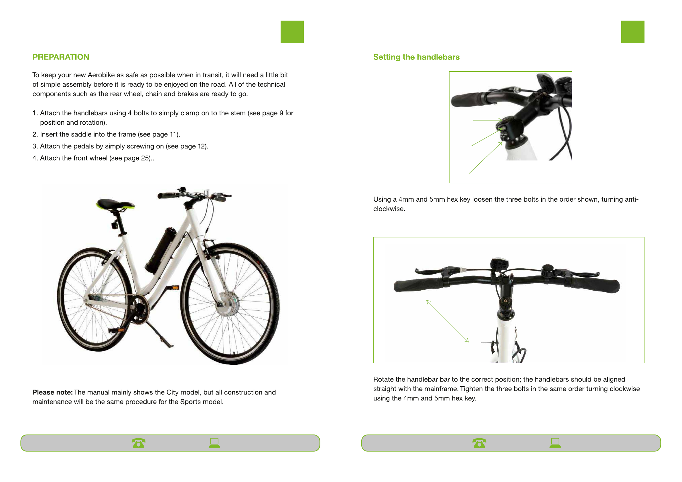
Preparation
Your new aerobike will be delivered to you fully assembled, all you will need to
do is adjust the handlebars and set to the correct positions.
Please note: The manual mainly shows the City model, but all construction and
maintenance will be the same procedure for the Sports model.
9
Seng the handlebars
Rotate the handlebar bar to the correct posion; the handlebars should be
aligned straight with the mainframe. Tighten the three bolts in the same order
turning clockwise using the 5mm hex key.
Using a 5mm hex key loosen the three bolts in the order shown,
turning an-clockwise.
1
2
3

11
User Guide
10
Setting the correct saddle height
Sitting on the bike with the pedal at the bottom position, try to reach the pedal
with your heel. Your knee should be more or less straight.
Move the pedal to a centre location; place the ball of your foot on the pedal if
your knee is slightly bent the saddle is at the correct height.
If you need to adjust the saddle height, follow the instructions overleaf.
11
Adjusting the saddle height
Missing image xxx
Pull back the quick release
lever.
Adjust the saddle height to the
correct height for you, making
sure that the minimum mark is
not above the seat tube.
Close the quick release by firmly
pushing on the quick release lever,
so that it lies flat against the
frame.
Check that the saddle cannot move
once the quick release is closed. If it
does move, tighten the adjusting nut
until you need to use the palm of
your hand to close the quick release
lever.
10

After Sales Support 0871 911 7003 [email protected] After Sales Support 0871 911 7003 [email protected]
12 13
User Guide User Guide
12
Adjusting the saddle travel
Locate the saddle adjustment
screw located on the underneath
of the saddle; loosen the screw by
turning a Hex key anti-clockwise.
Now that the saddle is loose it can be
moved horizontally, forward or
backwards to improve your reach to
the handlebars.
Once it is in the desired position, use a
5mm Hex key to tighten the adjustment
screw by turning it clockwise.
13
Attaching and removing the battery
To remove the battery, follow the steps in reverse order.
Operation
Before riding your aerobike check that the following steps have been
completed in accordance with these instructions in the assembly section.
Point to check
Yes.
If not see page
The wheels are mounted properly
The brakes work correctly
The seat is in the correct position
The saddle is comfortable
The bolts, nuts and screws are tightened
The pedals are firmly attached
The air pressure in the tyres are correct
The battery is charged and attached
Place the battery in to the battery
cradle, located on the down tube.
Secure the battery in place with the
securing strap.
Point to check Ye s If not see page
The wheels are mounted properly 23
The brakes work correctly 27
The seat is in the correct position 11
The saddle is comfortable 12
The bolts, nuts and screws are tightened 34
The pedals are firmly attached 12
The air pressure in the tyres are correct 17
The battery is charged and attached 13

After Sales Support 0871 911 7003 [email protected] After Sales Support 0871 911 7003 [email protected]
14 15
User GuideUser Guide
14
Charging the battery
The battery will need charging regularly and can be done so by using the
charging cable included with your aerobike. Always fully charge the battery
before storing. For optimum performance we recommend that you store the
battery indoors.
To check the level of battery power remaining simple press the button as seen
in the image above and the green lights will indicate the battery power.
The battery will take approximately3 hours to fully charge.
Turning your aerobike On and Off
To turn the battery on or off simply press the red button on the top of the
battery.
15
Brake Control
The le brake lever acvates the rear brake; the right brake lever acvates the
front brake.
You should regularly check your brakes to make sure that they are working
correctly.
The aerobike is fied with a switch that will automacally cut power to the
motor when the brake lever is pulled.
Always use both brakes together.

After Sales Support 0871 911 7003 [email protected] After Sales Support 0871 911 7003 [email protected]
16 17
User Guide User Guide
Inflating the tyres
Before starting to inflate your tyres check that the pump is in the correct mode for your
tyre valve.
Remove the valve cap. Briefly press down on the valve to make
sure that the valve doesn’t stick and to
remove any loose dirt.
17
Inflating the tyres
Before starting to inflate your tyres check that the pump is in the correct mode
for your tyre valve.
Remove the valve cap.
Briefly press down on the valve to make
sure that the valve doesn’t stick and to
remove any loose dirt.
Pull out the end of the bicycle pump
and pushdown to start inflating the
tyre, continue to do so until the tyre
has reached the desired tyre pressure.
Do not inflate the tyre beyond the
maximum tyre pressure. (You will find
this information printed on the
sidewall of the tyre).
Remove the pump and replace
the valve cap.
Pull out the end of the bicycle pump
and pushdown to start inflating the
tyre, continue to do so until the tyre
has reached the desired tyre pressure.
Do not inflate the tyre beyond the
maximum tyre pressure. (You will find
this information printed on the sidewall
of the tyre).
Remove the pump and replace the valve
cap.
17
Inflating the tyres
Before starting to inflate your tyres check that the pump is in the correct mode
for your tyre valve.
Remove the valve cap.
Briefly press down on the valve to make
sure that the valve doesn’t stick and to
remove any loose dirt.
Pull out the end of the bicycle pump
and pushdown to start inflating the
tyre, continue to do so until the tyre
has reached the desired tyre pressure.
Do not inflate the tyre beyond the
maximum tyre pressure. (You will find
this information printed on the
sidewall of the tyre).
Remove the pump and replace
the valve cap.
After Sales Support 0871 911 7003 [email protected] After Sales Support 0871 911 7003 [email protected]
18 19
User Guide User Guide
Detach the brakes, which are located
at the top front forks, from the front
wheel rim by closing the brake arms
with your thumb and index finger and
lifting out the brake cable, if there is not
enough play; loosen the adjusters at the
handlebars.
Place the frame upside down on a
flat surface and disconnect the power
cable.
Unscrew the bolt using a spanner. Remove the wheel.
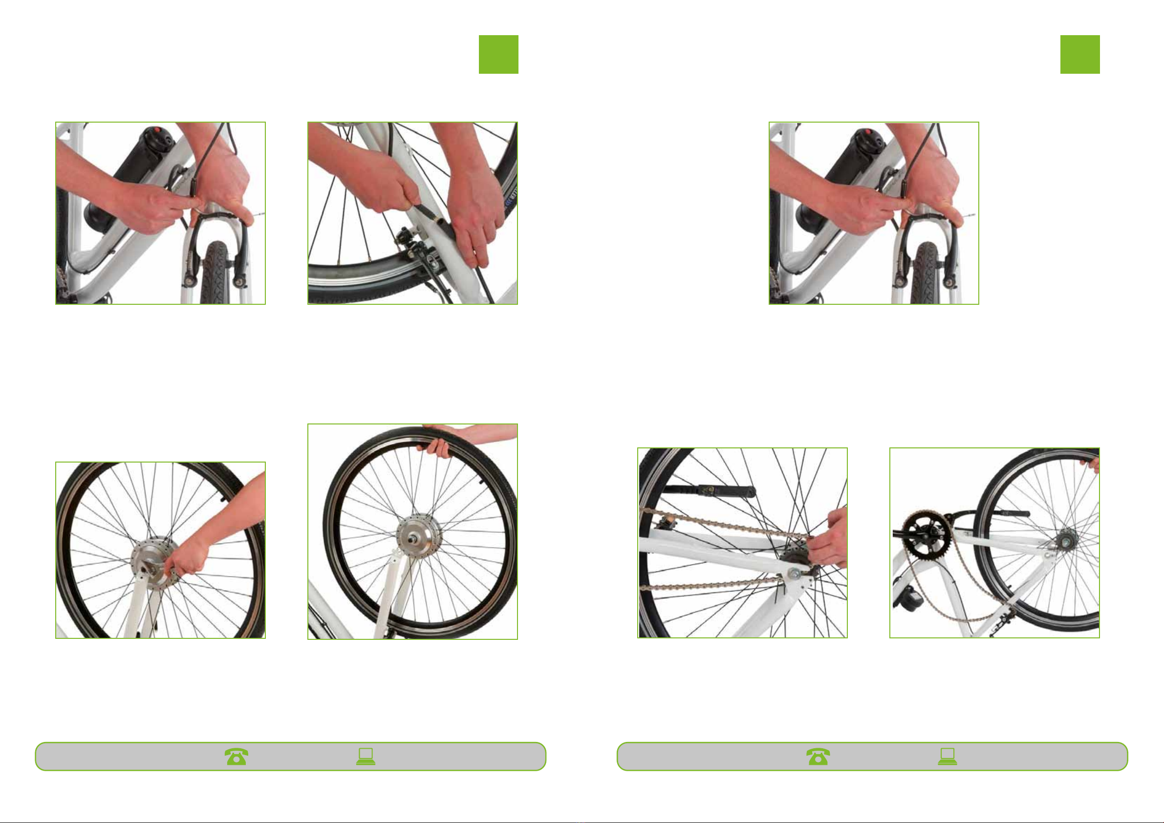
Removing the front wheel
18
Removing the front wheel
n
Detach the brakes, which are
located at the top front forks,
from the front wheel rim by
closing the brake arms with your
thumb and index finger and lifting
out the brake cable, if there is not
enough play; loosen the adjusters
at the handlebars.
Place the frame upside down on a
flat surface and disconnect the
power cable.
Unscrew the bolt using a
spanner.
Remove the wheel.
Detach the brakes, which are located at the top front forks, from the front wheel rim by
closing the brake arms with your thumb and index finger and lifting out the brake cable,
if there is not enough play; loosen the adjusters at the handlebars. Place the frame
upside down on a flat surface.
Loosen the bolts on either side of the
wheel by turning anti-clockwise. Slide
the wheel forward as far as you can
towards the frame to loosen the chain.
Slide the wheel backwards off the frame
to remove.
Removing the rear wheel
18
Removing the front wheel
n
Detach the brakes, which are
located at the top front forks,
from the front wheel rim by
closing the brake arms with your
thumb and index finger and lifting
out the brake cable, if there is not
enough play; loosen the adjusters
at the handlebars.
Place the frame upside down on a
flat surface and disconnect the
power cable.
Unscrew the bolt using a
spanner.
Remove the wheel.
19
Removing the rear wheel
Detach the brakes, which are located at the top front forks, from the front
wheel rim by closing the brake arms with your thumb and index finger and
lifting out the brake cable, if there is not enough play; loosen the adjusters at
the handlebars. Place the frame upside down on a flat surface.
Loosen the bolts on either side of
the wheel by turning anti-
clockwise. Slide the wheel forward
as far as you can towards the
frame to loosen the chain.
Slide the wheel backwards off the
frame to remove.

After Sales Support 0871 911 7003 [email protected] After Sales Support 0871 911 7003 [email protected]
20 21
User Guide User Guide
20
Replacing the inner tube
To replace the inner tube you will need a 700C x 35/43C inner tube. You will
also find it easier if you have a tyre lever tool, these can be purchased from
your local bike shop, if you will be changing the tyre at the same time you will
need a 700x35C tyre.
Remove the wheel from your
aerobike then remove the valve
cap.
Push a hex key into the valve
and push down to let all of the
air out. You may need to push
down on the tyre to help
remove the air, whilst still
pushing down on the tyre valve.
Push a tyre lever in underneath the
outer tyre. Push the tyre lever
upwards to pull the outer tyre over
the wheel rim. Run the tyre lever all
the way round the tyre.
Push the inner tube valve in,
towards the tyre.
21
Remove the inner tube from
between the outer tyre rim.
! Check the inside of the outer tyre for
sharp objects that may have damaged
the inner tube and remove them. Be
careful not to injure yourself.
Partially inflate the inner tube
Insert the inner tube at the valve
location, pulling the valve through the
hole in the rim.

After Sales Support 0871 911 7003 [email protected] After Sales Support 0871 911 7003 [email protected]
22 23
User Guide User Guide
Feed the rest of the inner tube evenly
around the inside of the tyre, be careful
not to twist or pinch the inner tube.
Use the tyre lever to push the edge of
the outer tyre under the wheel rim, all
the way round the tyre.
20
Replacing the inner tube
To replace the inner tube you will need a 700C x 35/43C inner tube. You will
also find it easier if you have a tyre lever tool, these can be purchased from
your local bike shop, if you will be changing the tyre at the same time you will
need a 700x35C tyre.
Remove the wheel from your
aerobike then remove the valve
cap.
Push a hex key into the valve
and push down to let all of the
air out. You may need to push
down on the tyre to help
remove the air, whilst still
pushing down on the tyre valve.
Push a tyre lever in underneath the
outer tyre. Push the tyre lever
upwards to pull the outer tyre over
the wheel rim. Run the tyre lever all
the way round the tyre.
Push the inner tube valve in,
towards the tyre.
22
Feed the rest of the inner tube
evenly around the inside of the tyre,
be careful not to twist or pinch the
inner tube.
Use the tyre lever to push the edge
of the outer tyre under the wheel
rim, all the way round the tyre.
Inflate the inner tube to the correct
pressure and secure with the valve
cap.
Refit the wheel to the aerobike.
Inflate the inner tube to the correct
pressure and secure with the valve cap.
Refit the wheel to the aerobike.
22
Feed the rest of the inner tube
evenly around the inside of the tyre,
be careful not to twist or pinch the
inner tube.
Use the tyre lever to push the edge
of the outer tyre under the wheel
rim, all the way round the tyre.
Inflate the inner tube to the correct
pressure and secure with the valve
cap.
Refit the wheel to the aerobike.
23
Attaching the rear wheel
Start by placing the frame upside down on a flat surface, resting on the saddle
and handlebars, you may need to put something down on the floor to prevent
the aerobike getting scratched.
Disconnect the battery and the brakes.
Make sure that the chain is resting on
the outside of the rear fork.
Slot the rear sprocket into the
rear wheel fork, making sure
that it is on the same side as the
pedal sprocket.
Slide the wheel back into place,
keeping it pushed forward on the
rear fork, this will reduce the
distance between the sprockets,
making it easier to attach the
chain.
Replace the chain onto the
rear wheel sprocket, making
sure the teeth are lined up.

After Sales Support 0871 911 7003 [email protected] After Sales Support 0871 911 7003 [email protected]
24 25
User Guide User Guide
24
Rotate the pedals slowly and
line up the teeth to feed the
slackened chain on to the
sprocket.
Slide the rear wheel
backwards, making sure that
the chain stays on the
sprockets, this creates the
tension on the chain.
Tighten the bolts ensuring the
chain has no slack and the
wheel is aligned straight.
Turn the aerobike the correct way
up and re attach and adjust the
brakes. You will also need to
reconnect the battery.
Attaching the front wheel
Remove the rubber cap from the
right hand nut and loosen the nuts
and washers on either side of the
motor. There is no need to remove
them completely.
Slot the axel of the front wheel into
the front forks. Ensuring the lip of
the inside washer closest to the
motor fills the gap of the forks.
Tighten the nuts using a spanner.
Replace the rubber cap over the
right hand nut.
Tighten the nuts using a spanner.
Please note: There may be an
additional washer that hooks into
the outside of the front forks.
Attaching the rear wheel (continued)
After Sales Support 0871 911 7003 [email protected] After Sales Support 0871 911 7003 [email protected]
26 27
User Guide User Guide
25
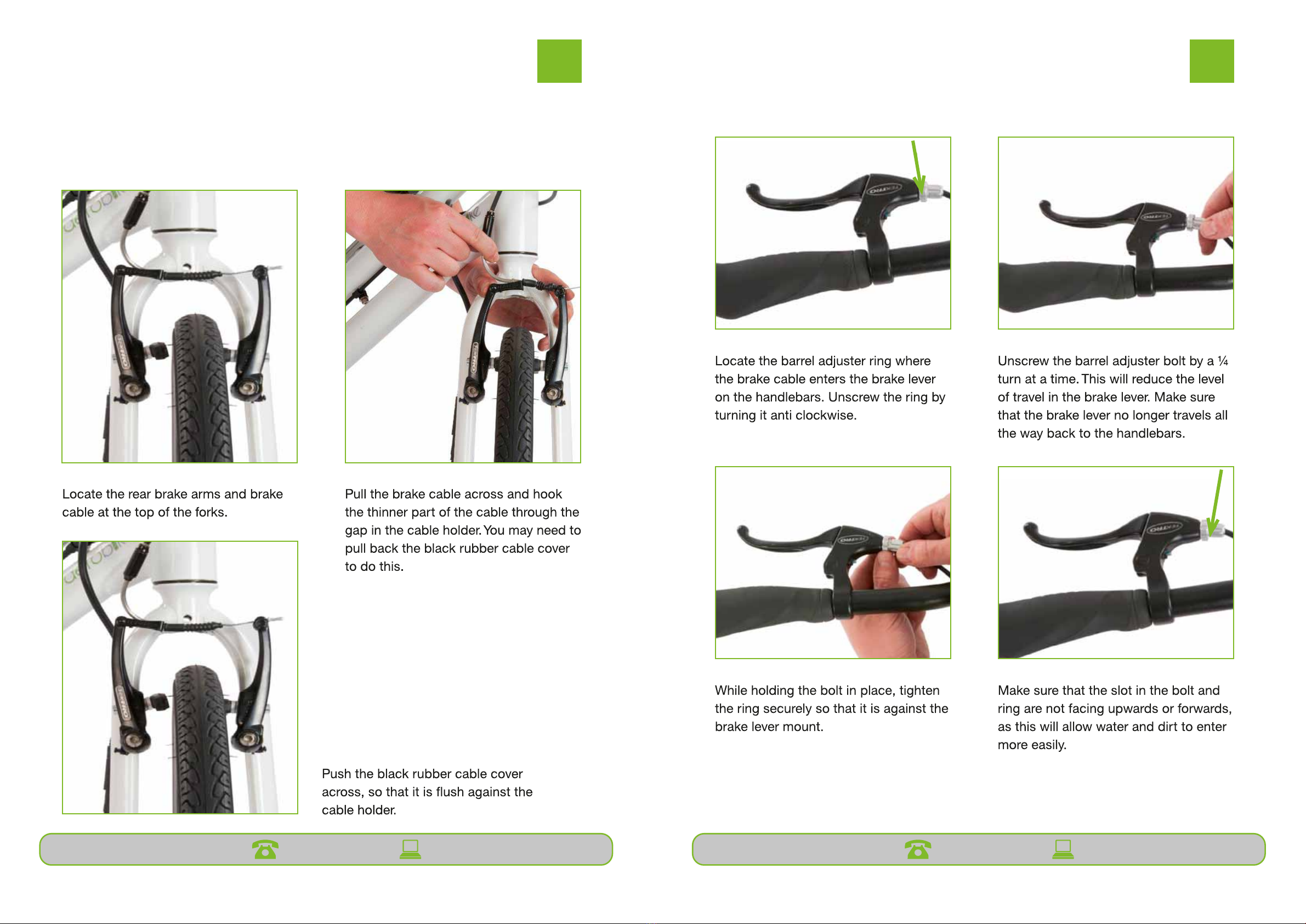
Assembling the brakes
These instructions apply to both front and rear brakes, remember to check
them regularly and adjust as necessary.
Locate the rear brake arms
and brake cable at the top of
the forks.
Pull the brake cable across and
hook the thinner part of the cable
through the gap in the cable
holder. You may need to pull back
the black rubber cable cover to do
this.
Push the black rubber cable
cover across, so that it is flush
against the cable holder.
25
Assembling the brakes
These instructions apply to both front and rear brakes, remember to check
them regularly and adjust as necessary.
Locate the rear brake arms
and brake cable at the top of
the forks.
Pull the brake cable across and
hook the thinner part of the cable
through the gap in the cable
holder. You may need to pull back
the black rubber cable cover to do
this.
Push the black rubber cable
cover across, so that it is flush
against the cable holder.
Adjusting the brakes
26
Adjusting the brakes
Locate the barrel adjuster ring where
the brake cable enters the brake lever
on the handlebars. Unscrew the ring by
turning it anti clockwise.
Unscrew the barrel adjuster bolt by
a ¼ turn at a time. This will reduce
the level of travel in the brake
lever. Make sure that the brake
lever no longer travels all the way
back to the handlebars.
While holding the bolt in place, tighten
the ring securely so that it is against the
brake lever mount.
Make sure that the slot in the bolt
and ring are not facing upwards or
forwards, as this will allow water and
dirt to enter more easily.
Adjusting the brakesAssembling the brakes
These instructions apply to both front and rear brakes, remember to check them
regularly and adjust as necessary.

After Sales Support 0871 911 7003 [email protected] After Sales Support 0871 911 7003 [email protected]
28 29
User Guide User Guide
25
Assembling the brakes
These instructions apply to both front and rear brakes, remember to check
them regularly and adjust as necessary.
Locate the rear brake arms
and brake cable at the top of
the forks.
Pull the brake cable across and
hook the thinner part of the cable
through the gap in the cable
holder. You may need to pull back
the black rubber cable cover to do
this.
Push the black rubber cable
cover across, so that it is flush
against the cable holder.
27
Adjusting brake travel
Your brake pads should hit the wheel rim at the same time; if this doesn’t
happen then you will need to adjust them.
Make sure that there is not an excess
of brake cable between the brake
arms. If there is excess cable, follow
the instructions in this manual to
adjust brake cable. If there is no
excess, continue to follow the
instructions on this page.
Locate the brake spring adjuster
screws at the bottom of the
brake arm that is moving towards
the wheel rim the slowest. You
will need a Phillips head
screwdriver for this.
Turn the screw slightly clockwise to tighten it,
until the gaps are equal on either side and the
brake pads touch the rim simultaneously. You
may need to loosen the screw on the opposite
brake arm by turning it anti-clockwise to do this.
The brakes on either side of the
wheel rim should now appear
symmetrical when applied.
Adjusting brake travel
Your brake pads should hit the wheel rim at the same time; if this doesn’t happen then
you will need to adjust them.
After Sales Support 0871 911 7003 [email protected] After Sales Support 0871 911 7003 [email protected]
30 31
User Guide User Guide
17
Inflating the tyres
Before starting to inflate your tyres check that the pump is in the correct mode
for your tyre valve.
Remove the valve cap.
Briefly press down on the valve to make
sure that the valve doesn’t stick and to
remove any loose dirt.
Pull out the end of the bicycle pump
and pushdown to start inflating the
tyre, continue to do so until the tyre
has reached the desired tyre pressure.
Do not inflate the tyre beyond the
maximum tyre pressure. (You will find
this information printed on the
sidewall of the tyre).
Remove the pump and replace
the valve cap.
29
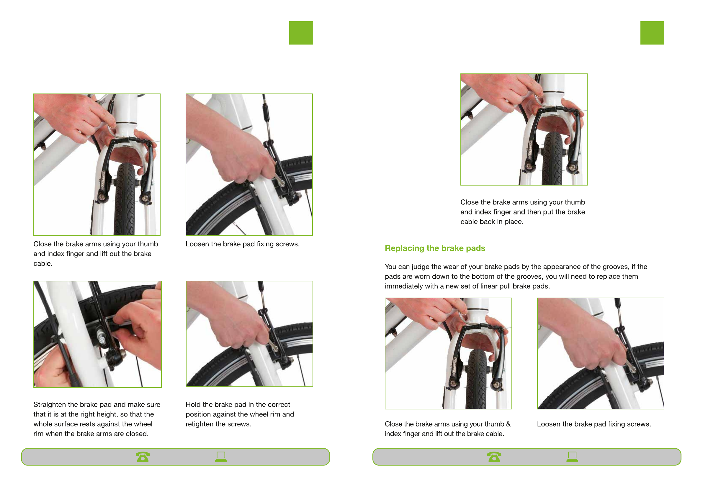
Aligning the brake pads
The brake pads on your bike should be accurately aligned against the wheel
rim.
Close the brake arms using your
thumb and index finger and lift
out the brake cable.
Loosen the brake pad fixing screws.
Straighten the brake pad and make
sure that it is at the right height, so
that the whole surface rests against
the wheel rim when the brake arms
are closed.
Hold the brake pad in the correct
position against the wheel rim and
retighten the screws.
25
Assembling the brakes
These instructions apply to both front and rear brakes, remember to check
them regularly and adjust as necessary.
Locate the rear brake arms
and brake cable at the top of
the forks.
Pull the brake cable across and
hook the thinner part of the cable
through the gap in the cable
holder. You may need to pull back
the black rubber cable cover to do
this.
Push the black rubber cable
cover across, so that it is flush
against the cable holder.
Aligning the brake pads (continued)Aligning the brake pads
The brake pads on your bike should be accurately aligned against the wheel rim.

After Sales Support 0871 911 7003 [email protected] After Sales Support 0871 911 7003 [email protected]
32 33
User Guide User Guide
31
Remove the old brake pad.
Make sure to keep any
screws and washers.
Insert the new brake pad; screw the new
brake pads into place.
Hold the brake pad so that it’s
whole surface rests against the
wheel rim and re-tighten.
Close the brake arms using
your thumb and index finger
and put the brake cable back
in place.
25
Assembling the brakes
These instructions apply to both front and rear brakes, remember to check
them regularly and adjust as necessary.
Locate the rear brake arms
and brake cable at the top of
the forks.
Pull the brake cable across and
hook the thinner part of the cable
through the gap in the cable
holder. You may need to pull back
the black rubber cable cover to do
this.
Push the black rubber cable
cover across, so that it is flush
against the cable holder.
After Sales Support 0871 911 7003 [email protected] After Sales Support 0871 911 7003 [email protected]
34 35
User Guide User Guide
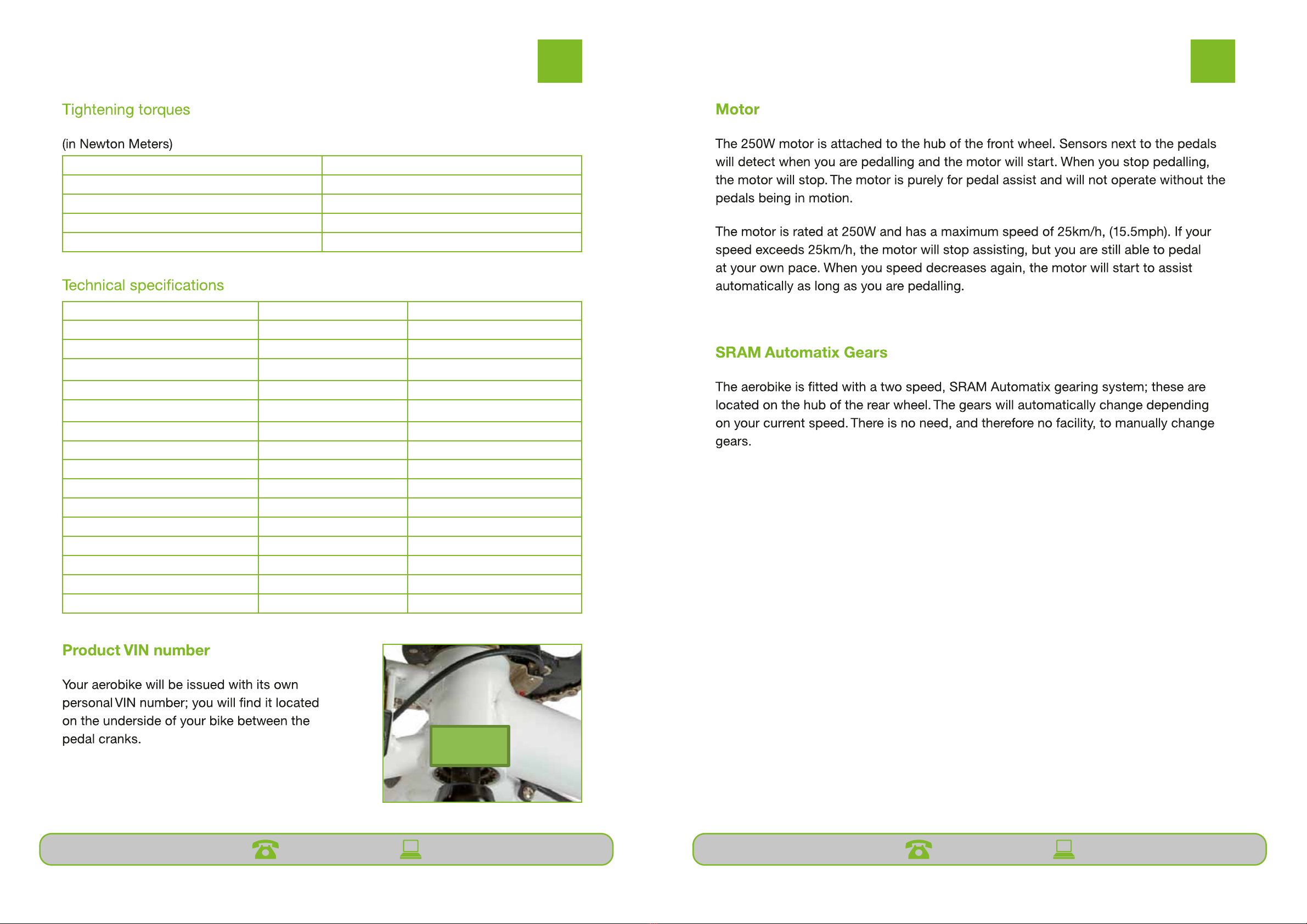
33
Tightening torques
(in Newton Meters)
Handlebars
5Nm
Handlebar stem
8Nm
Saddle
22Nm
Motor
40Nm
Technical specifications
Sports
City
Frame Size
20 inch
20 inch
Frame Construction
Aluminium
Aluminium
Bike Weight (not incl
battery)
16kg
16kg
Brake Type
Linear Pull/V-Brake
Linear Pull/V-Brake
Wheel Size
28 inch / 700c
28 inch / 700c
Tyre Type
Hybrid
Hybrid
Motor
250W
250W
Warranty
1 Year
1 Year
Range
30 miles
30 miles
Charge Time
3 hours
3 hours
Battery Type
Lithium Ion
Lithium Ion
Voltage
36V
36V
Amp Hours
5.8Ah
5.8Ah
Detachable
Yes
Yes
Battery Weight
1.3kg
1.3kg
Product VIN number
Your aerobike will be issued with its own personal VIN number; you will find it
located on the underside of your bike between the pedal cranks.
Handlebars 8Nm
Handlebar stem 8Nm
Saddle 15Nm
Motor 30Nm
Rear wheel 20Nm
Sports City
Frame Size 20 inch 20 inch
Frame Construction Aluminium Aluminium
Bike Weight (not incl battery) 16kg 16kg
Brake Type Linear Pull/V-Brake Linear Pull/V-Brake
Wheel Size 28 inch / 700c 28 inch / 700c
Tyre Type Hybrid Hybrid
Motor 250W 250W
Warranty 1 Year 1 Year
Range 30 miles 30 miles
Charge Time 3 hours 3 hours
Battery Type Lithium Ion Lithium Ion
Voltage 36V 36V
Amp Hours 5.8Ah 5.8Ah
Detachable Ye s Ye s
Battery Weight 1.3kg 1.3kg

36
User Guide
Every Ride (Basic
Safety Check)
Monthly
(or 400 miles)
Six Monthly
(or 2000 miles)
Yearly
(or 4000 miles)
Check tyre pressure Clean frame with a
cloth. Inspect frame
and components for
signs of wear, cracks
or other damage
Clean and wax the
frame to protect the
finish
Check all bearing
systems such as
headset and pedals
Check tyre tread for
wear and debris
Clean the chain with
a degreaser and re-
lubricate chain and
sprockets
Check tyres for
wear, rotting or
cracks
Check wheels
carefully for any
signs of wear such
as worn sidewalls
and cracks
Check that any
quick release parts
are tight and secure
Check for loose
spokes
Check cables and
cable housings for
breaks, cracks,
fraying or corrosion
Check wheels run
smooth and straight
Check bolts are all
ight and secure
(handlebars, wheels,
Check for worn
brake pads and
handlebar grips
Check brakes work,
touch the rim (not
the tyres) and that
the pads are not
worn
Lubricate brake and
pedal pivot point
Check for any chain
or sprocket wear
Check that chain is
lubricated and not
dry
Lubricate brake
cables and check
for fraying and
rusting
Ensure battery is
fully charged
If the battery has
not been used, fully
charge to prolong
life.
35
Plug Wiring
These safety instructions should be read carefully and kept in safe place for future
reference.
This appliance is fitted with a plug that complies with BS 1363. Only high quality 13A (square
pin) plugs that comply with this standard should be fitted.
Wires are coloured as follows:
Brown –Live
Blue –Neutral
Yellow & Green –Earth
If the appliance is fitted with a 2-core cable it is double insulated and will not have the
yellow and green earth wire.
IT IS ESSENTIAL THAT WIRES ARE ATTACHED ONLY TO THEIR DESIGNATED POSITIONS IN
THE PLUG
Fuses must be replaced with the same rating as the original; please refer to the fuse rating stated
on the plug for this information. Only genuine fuses compliant with BS 1362 should be use
Plug Wiring
37
After Sales Support 0871 911 7003 [email protected] After Sales Support 0871 911 7003 [email protected]
38 39
User Guide User Guide
Notes
This manual suits for next models
7
Table of contents


