Aerobits TR-1F User manual
www.aerobits.pl
ADSB In/Out
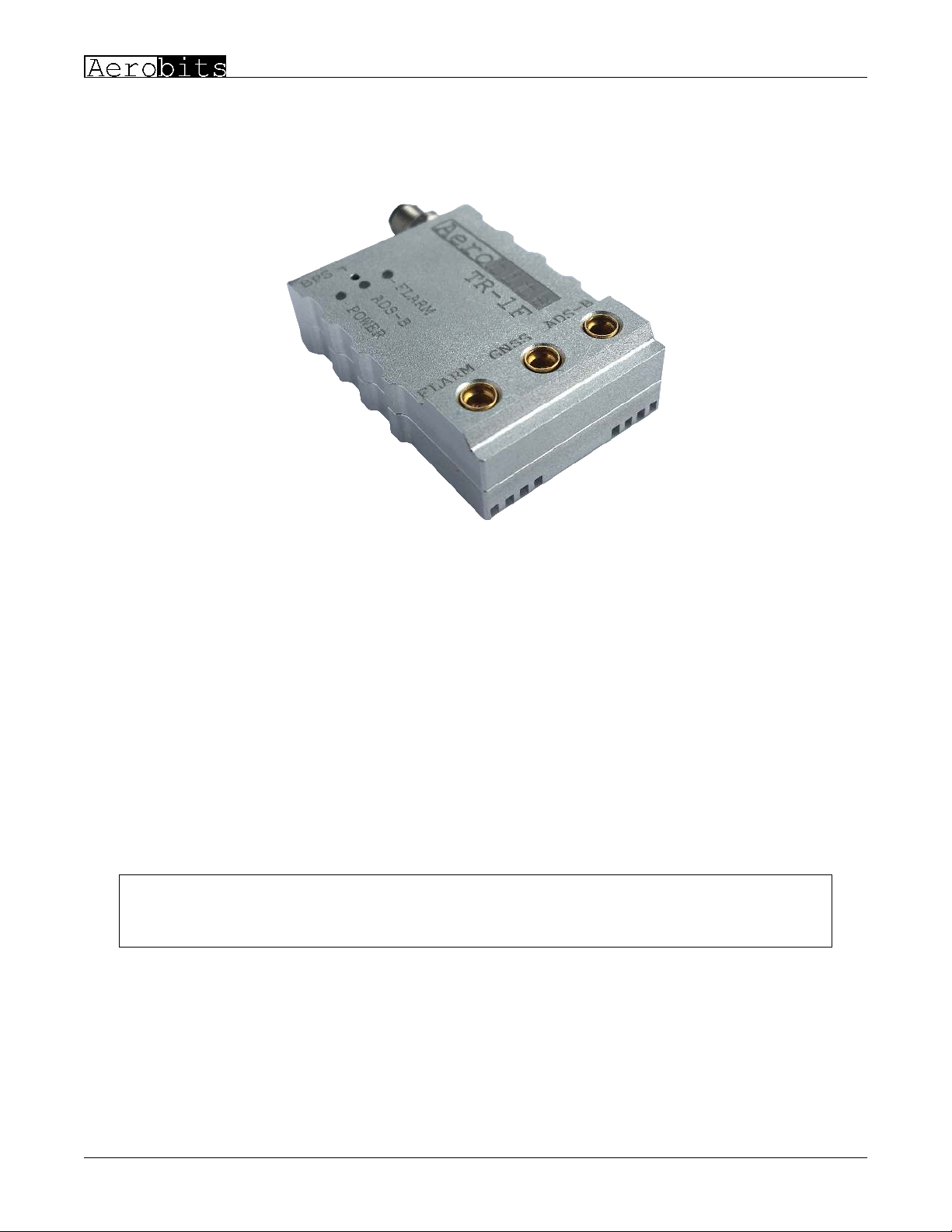
TR1F belongs to the generation of the smallest transceivers on market and supports two technologies: ADSB and FLARM.
It has been developed to support civil and commercial Unmanned Aircraft Systems as well as General Aviation. The device
operates on 1090MHz and 868 MHz and allows to receive and transmit ADSB and FALRM data with defined 0.25, 0.5 or 1 Watt
output power for ADSB and 0,025W for FALRM. The transceiver does not require external devices to operate. It is equipped
with a high quality multiGNSS receiver and a pressure sensor. The aluminium housing and ESD protection guarantee high
resistance of the device to work in difficult conditions. TR1F opens the way to the safe integration of UAS into nonsegregated
airspace, implementation of the Detect and Avoid algorithms and reduce separation between airspace users.
The device to operate on FLARM frequency requires FLARM UAS licence. The licence can be obtained with the
device from Aerobits upon purchase.
ICAO addresses are used to provide a unique identity normally allocated to an individual aircraft or registration.
Address becomes a part of the aircraft’s Certificate of Registration and MUST be given by Civil Aviation
Authority and registered in aircraft database.
• Realtime aircraft tracking on 1090MHz and 868 MHz
• Patented FPGAInTheLoop TM technology with the capability of receiving thousands of frames per second
• Integrated GNSS source and pressure sensor
Revision: 09March20 Document Number: 090320
This document is subject to change without notice. For technical questions, contact: [email protected]
1

www.aerobits.pl
ADSB In/Out
• Configurable 0.25/0.5/1 Watt RF output power for ADSB
• Licensed FLARM transceiver (0.025 Watt output power)
• Implemented MAVLink and AERO TM protocol
• Lowpower consumption and low weight design
• Simple plug&play integration
• Programming via AT commands
• Designed to meet MOPS DO260B (except the output power)
• Dimension: 35.0x25.0x8.5mm
Frequency ADSB 1090MHz, FLARM 868 MHz (jumping depending on
region between xxxxxx)
Input voltage 5V
Current consumption 180mA
Sensitivity 80dBm
RF Output power Configurable +30dBm, +27dBm, +24dBm
ESD protection All lines
MAVLink (baud) 115200bps
AERO (baud) 115200bps (AT commands)
Main connector PXMBNI05RPM04APC
Antenna connector 2x MMCX
Dimension 35.0x25.0x8.5mm
Weight (without cables and antennas) 14grams
Table 1: Technical parameters.
1 Red +5V Power supply (5V/70mA)
2 Green TX Data from device to host
3 White RX Data from host to device
4 Black GND Ground
Table 2: Electrical parameters
Revision: 09March20 Document Number: 090320
This document is subject to change without notice. For technical questions, contact: [email protected]
2

www.aerobits.pl
ADSB In/Out
Figure 1: Module overview
Green Power supply indicator
White Frame detection / receive indicator
Red ADSB OUT indicator 1. OFF – Disabled 2. Blink – Wait for FIX 3. ON – Active
Table 3: LED indicators
All dimensions in mm (tolerances ±0.1mm)
Revision: 09March20 Document Number: 090320
This document is subject to change without notice. For technical questions, contact: [email protected]
3

www.aerobits.pl
ADSB In/Out
Main Installed on board BULGIN, PXMBNI05RPM04APC
Mating connector BULGIN, PXPPVC05FBF04ACL010PVC
Antenna Installed on board MOLEX, 734151061
Mating connector MOLEX, 733660010
Table 4: Mechanical parameters
TR1F is a standalone device and in the simplest case of its operation requires only a power supply. However during the first
startup, you must configure the device. That can be performed in the few steps described below. First install the antennas using
the MCX> SMA adapters included in the kit. Also connect the configuration cable that will help you set the device parameters.
The following figure shows the installation method.
Figure 2: Combination overview
1. Connect the device to the PC. The converter is supplied with the FTDI chip. In this case, the installation of the controller
takes place automatically.
2. Download the latest Micro ADSB software from www.aerobits.pl. Install Micro ADSB on your Windows computer. If
the device is connected to a PC, it should be found automatically after clicking the ”Connect” button. The connection window
should look similar to the one in the picture.
Select the device found and press ”OK”.
Revision: 09March20 Document Number: 090320
This document is subject to change without notice. For technical questions, contact: [email protected]
4

www.aerobits.pl
ADSB In/Out
Figure 3: Port select window
3. Press ”Settings” to enter the parameterization mode of the module. After setting the parameters, press the ”Ok” button to
save the settings. TR1F is ready to work.
Figure 4: Settings window
1. Module installation – There is a high concentration of various electronic systems on a small area at UAS. Try to keep as much
separation between TR1F and other devices, especially radio ones. Despite the high robustness of TR1F to jamming, try to
install the antenna away from other onboard systems.
2. AERO vs. MAVLink protocol – TR1F is based on OEM TTSF1a module. The default is in AERO protocol mode, which
is an ASCII protocol. If you want to use the module to work with MAVLink system, it is possible to switch the protocol to
MAVLink, which has the binary representation. Details of the module programming can be found on the website.
Revision: 09March20 Document Number: 090320
This document is subject to change without notice. For technical questions, contact: [email protected]
5
www.aerobits.pl
ADSB In/Out
09March20 1 Initial release.
Table 5: Document revision history.
Revision: 09March20 Document Number: 090320
This document is subject to change without notice. For technical questions, contact: [email protected]
6
www.aerobits.pl
ADSB In/Out
Please read carefully
Information contained in this document is provided solely in connection with Aerobits products. Aerobits reserves the right to
make changes, corrections, modifications or improvements to this document, and to products and services described herein at
any time, without notice. All Aerobits products are sold pursuant to our own terms and conditions of sale. Buyers are solely
responsible for the choice, selection and use of the Aerobits products and services described herein, and Aerobits assumes no
liability whatsoever, related to the choice, selection or use of Aerobits products and services described herein. No license,
express or implied, by estoppel or otherwise, to any intellectual property rights is granted under this document. If any part of
this document refers to any third party products or services, it shall not be deemed a license granted by Aerobits for use of such
third party products or services, or any intellectual property contained therein or considered as a warranty covering use, in any
manner whatsoever, of such third party products or services or any intellectual property contained therein.
Information in this document supersedes and replaces all previously supplied information.
© 2020 Aerobits All rights reserved
Revision: 09March20 Document Number: 090320
This document is subject to change without notice. For technical questions, contact: [email protected]
7
Table of contents


