AeroGT Labs RN200 mono User manual

RN200 mmWave OTA Test System
AeroGT Labs
October 20, 2022

2
2022 © Copyright AeroGT Labs. All rights reserved.
No part of this document may be reproduced or transmitted in any form or by any means, or
stored in any retrieval system of any nature without prior written from AeroGT Labs.
Notice
This document may be updated due to product upgrades or for other reasons. AeroGT Labs
will not notify you such information updates.
File name RN200 mmWave OTA Test System User Manual
Document
number GTS-PC-SD-008
Document
version A1 2022/9/23
Revision of records
Edition Date Prepared
by
Reviewed
by Approved by Revision notes
A0 2022/8/12 YX. JIANG L. QIN J. LI First release
A1 2022/9/23 YX. JIANG L. QIN J. LI
Updated unpacking
instruction & interface
panel description
A2 2022/10/5 Steve
Wong Grammar/formatting
check/review/correction
Contact
AeroGT Labs
42840 Christy Street, Suite 110
Fremont, CA 94538
Phone: +1-510-438-9548
Email: info@aerogtlabs.com

3
Contents
1 Product Introduction.................................................................................................................................................... 1
1.1 System Overview ............................................................................................................................................. 1
1.2 System Structure.............................................................................................................................................. 1
1.3 Product Features.............................................................................................................................................. 4
1.4 System Functions............................................................................................................................................. 5
2 Hardware Introduction................................................................................................................................................. 7
2.1 System Layout.................................................................................................................................................. 7
2.2 Coordinate Systems ......................................................................................................................................... 8
2.3 Interface Panel................................................................................................................................................. 8
3 System Diagram.......................................................................................................................................................... 10
3.1 Passive Test.................................................................................................................................................... 10
3.1.1 Passive test with built-in test module ............................................................................................... 10
3.1.2 Passive test with test instrument ...................................................................................................... 10
3.2 Active Test / RF Test....................................................................................................................................... 12
3.2.1 Active/non-signaling RF test with built-in test module..................................................................... 12
3.2.2 Active/Signaling RF test with test instrument................................................................................... 13
3.2.3 Active/non-signaling RF test with test instrument............................................................................ 13
4 Unpacking Instructions............................................................................................................................................... 15
5 Installation Guide ....................................................................................................................................................... 18
6 System Power On ....................................................................................................................................................... 19
7 Safety and Warning .................................................................................................................................................... 20
7.1 Precautions of device usage .......................................................................................................................... 20
7.2 Precautions of personal safety ...................................................................................................................... 20
8 Maintenance .............................................................................................................................................................. 21
8.1 Cable and grounding inspection .................................................................................................................... 21
8.2 Device exterior cleaning ................................................................................................................................ 21
9 Troubleshooting ......................................................................................................................................................... 21
9.1 System exceptions ......................................................................................................................................... 21
9.2 Abnormal Test Results ................................................................................................................................... 23
9.3 Device Verification......................................................................................................................................... 23

RN200 Mono Software User Manual
1
1Product Introduction
1.1 System Overview
The RN200 mmWave OTA (Over-the-Air) Test System is designed to perform transceiver tests
for 5G FR2 wireless devices and mmWave radar. It is compact in size, supports a large quiet
zone, offers multiple functions, and is an all-in-one millimeter wave test solution. The RN200
provides a complete solution that can act both as a "test platform and test system." This is a
general software and a cloud-based service platform for R&D applications. Engineers can verify a
device-under-test’s (DUT) OTA performance and perform signal processing, and algorithm tests
according to various technical requirements.
This system supports many functions: arbitrary vector signal generation (VSG), arbitrary
vector signal analysis (VSA), spectrum analysis, S21 amplitude/phase measurements and signal
quality analysis. It can also be upgraded to perform mmWave radar/module amplitude and
phase calibration and target simulation. The software platform provides a convenient
development method that enables the platform to run user-defined tests.
The RN200’s (Figure 1) all-in-one design makes it easy to install and relocate in a typical
office or laboratory environment.
Figure 1: Exterior View of the RN200
1.2 System Structure
The RN200 system is designed on the concept of “simple & fast.” All RF cables and
mechanical parts of the positioner (turntable) are intentionally installed at the rear and bottom

RN200 Mono Software User Manual
2
of the unit, and the DUT fixture is made of electromagnetically transparent material. The design
ensures an optimal measurement environment.
The system is composed of a shielding enclosure with absorbing material, positioner, ODC
baseband test module, mmWave frequency convertors, RF link, test automation software, and
other auxiliary modules. A system block diagram is shown in Figure 2.
Compact Field OTA Test System
Baseband test
module ODC200
Mmwave frequency
convertor
Absorbing material
Positioner
Other auxiliary
modules
Test autom ation
software
Shielded enclosure
RF link
Figure 2: RN200 Block Diagram
Each RN200 module is described as follows.
1. The baseband test module ODC200 VSG/VSA, designed for vector signal generation and
analysis, is ideal for 5G non-signaling FR1/FR2 testing. Its multiple RF input/output
channels support the real parallel test, which can improve test efficiency and significantly
reduce the test cost. Meanwhile, this module’s control interface is based on an open
design, where users can generate and analyze arbitrary signal waveforms.
2. The mmWave frequency converter is used for testing mmWave devices. It upconverts
signals from 4GHz~5GHz to 24GHz~43.5GHz and vice versa. Users can test mmWave
devices’ performance without using any additional mmWave test instrument. The
mmWave frequency converter provides up to a 40dB power adjustment range and helps
to control the measured signal level to be within a reasonable range.
3. The shielded enclosure, also known as the microwave chamber, is mainly used to isolate
electromagnetic signals, create a closed electromagnetic environment, provide a

RN200 Mono Software User Manual
3
controllable environment for testing without any interference or reflection, and ensure
the whole test process is not affected by any other extraneous factors.
4. Absorbing material is one of the core components of an anechoic chamber. The RN200 is
equipped with GTS EPP rigid foam absorbers. Its optimized structure design ensures
excellent electromagnetic wave absorption performance.
5. The positioner is the load-bearing platform for the device-under-test (DUT) and is
another core component of the chamber. It is used to support and rotate the DUT and
provide high-precision motion control for testing the DUT.
6. The RF link mainly includes some RF components such as mmWave feeds, reflectors,
transmission cables, amplifiers and RF switches, which undertake the signal controlling,
transmission and processing functions during test, support the testing of communication
functions in different frequency bands.
7. The test automation software controls the test system according to tester’s commands
and execute specific test tasks. The software has many features, such as wide range
applications, flexible configuration, smooth testing process, stable and reliable operation,
simple and friendly GUI.
8. Other auxiliary modules, including system control, grounding (GND), and power supply.

RN200 Mono Software User Manual
4
1.3 Product Features
1. Tight integration: This system integrates a mmWave chamber, test instruments, signal
links, and a system control module into one unit, reducing system integration complexity.
By turning the RN200 into a full-function test system, the RN200 can cover passive test,
active test and RF performance test; it can also be upgraded to support mmWave
phase/amplitude calibration and radar target simulations. The RN200 fully covers a
mmWave device’s R&D test requirements from antenna design, modular test to whole
device performance evaluation, and it is a versatile “test tool” for design engineers to do
debugging and performance verification. Meanwhile, the integrated design ensures high
system test accuracy that delivers results that are superior to the conventional “chamber
+ instrument” types.
2. Flexible configuration: The test function configuration process is flexible. Different users
or different applications can utilize particular test functions such as passive test, active
test and RF test, etc. Customers can select one or multiple test functions for the system
to help save on costs, and to eliminate system redundancy.
3. Compact size: The RN200’s exterior dimensions are 700mm (L) × 620mm (W) × 950mm
(H) and weighs less than 140kg. It can be placed on a test bench, allowing engineers to
carry out debugging and verification tasks in a small space.
4. Cost-effective: The built-in test module provides general-purpose, high-performance test
functions such as those provided by a basic spectrum analyzer, vector network analyzer,
and signal analyzer. Eliminating unneeded test functions lowers test equipment costs.
The RN200 is more cost-effective than conventional mmWave OTA systems.
5. Patented reflector design: The RN200 has a serrated edge reflector which is seamlessly
surrounded by absorbers; such a design improves the quality of the quiet zone. Its
average amplitude variation within the quiet zone is less than ±1dB and its average phase
variation is less than ±5°.

RN200 Mono Software User Manual
5
1.4 System Functions
The RN200’s system functions are shown in Table 1.
FUNCTION TEST CASE DESCRIPTION
Passive Test Antenna pattern for 3/4
hemisphere
S21 amplitude and phase response
Active Non-
signaling Test
Tx test Transmission antenna pattern, TRP, 3D
beam scan and spherical coverage,
spectrum test (OBW, SEM, ACLR) and
signal quality test (frequency error, LO
leakage, EVM, etc.)
Note: Tx signal can be a user-defined
arbitrary wave
Rx test Receiving power level, receiving
sensitivity (DUT should support signal
demodulation)
Note: system receives arbitrary signal
from DUT, then upload data to PC for
data/algorithm analysis
RF Test
Spectrum analysis Observe signal spectrum
Network analysis S21 amplitude/phase response
Time domain analysis Analyze time-domain signal from DUT
Others
Phased-array antenna
amplitude/ phase calibration.
Radar calibration, radar target
simulation
Upgradable
Table 1: The RN200 System Functions

RN200 Mono Software User Manual
6
Name RN200A/B
Frequency (GHz) 24~43.5(A) / 59~86(B)
Shielding >70dB
Weight <140kg
Power <500W
Positioner Phi: -180°~180°
Theta: -135°~135°
Quiet Zone (QZ) 200 x 200 x 200mm
7.9 x 7.9 x 7.9 inch
QZ Amplitude Variation <±1dB
QZ Phase Variation <±5°
Dimensions 700L×620W×950H
24.4 x 37.2 x 27.8 inch
Max. DUT Weight <5 kg
Passive Test Accuracy <1 dB
TRP Accuracy <1 dB
Repeatability <0.5 dB
Compatibility Support built-in test module and standard test instruments
Table 2: Technical Specifications of the RN200

RN200 Mono Software User Manual
7
2Hardware Introduction
2.1 System Layout
The mmWave chamber inner structure is shown in Figure 3.
Figure 3: RN200’s Inner Structure
The RN200’s major hardware modules are listed in Table 3.
Module Name Description
Feeds With H and V polarization
Reflector Converting spherical waves to plane waves and vice
versa
Positioner
(Turntable) Movement along Phi axis/Theta axis
LAN port For external connection and control of the DUT
USB port For external connection, control and power supply of
the DUT
DUT Device under test, passive DUT is connected to the
RF port on the positioner directly.
Table 3: Major Hardware Modules of RN200


RN200 Mono Software User Manual
9
The RN200 interface panel is described in Table 4.
Table 4: Interface of the RN200
Name Description
Power Button Power on or off the hardware. After the system boots up, the light on
the button will turn green.
Instrument
Switch
Turn to "Internal Instrument" to use the built-in test module.
Turn to "External Instrument" to use an external test instrument.
A blue light indicates the internal/external instrument is in use.
Signal Indicator
A red light indicates an error.
A blinking yellow light indicates that the system is booting up.
A green light indicates a normal status and the system is operating
normally.
RF Ports for
External Instrument
H: H polarization of the feed
V: V polarization of the feed
PSV: Passive antenna test port
CA: Communication antenna port
USB-B Port Connect to the USB port of the control PC and can be used to check
the system status if necessary.
LAN Port This device connects to an ethernet network via this port, providing a
connection with the control PC.
Power Port 110V/220V AC power supply.

RN200 Mono Software User Manual
10
3System Diagram
3.1 Passive Test
3.1.1 Passive test with built-in test module
An example of test system setup when using the internal test module is shown in Figure 6.
Figure 6: Passive Test System Diagram (with ODC200)
Cables connection instructions:
1. Direct connection to the RN200 to the control PC via the LAN port with an RJ45 cable or
connect to a network switch (optional) firstly then connect to the control PC indirectly.
2. Use a USB cable, and connect the device’s USB Type-B port on the interface panel with
the USB port of the control PC.
3. Connect the DUT to the RF port on the positioner with an RF cable.
3.1.2 Passive test with test instrument
An example of test system setup when using a standard test instrument is shown in Figure
7.
RN200 Mono Software User Manual
11
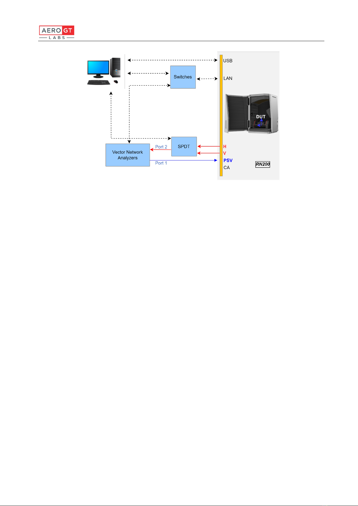
Figure 7: Passive Test System Diagram (with Test Instrument)
Cables connection instructions:
1. Connect both the device’s LAN port and the VNA’s LAN port to a network switch; then
connect the control PC to a network switch with an RJ45 cable.
2. Using a USB cable, connect the device’s USB Type-B port on the interface panel with a
USB port on the control PC.
3. Connect the DUT to the RF port on the positioner with an RF cable.
4. Connect Port1 of the VNA to the PSV port on the interface panel, and connect Port2 of
VNA to SPDT (RF switch); the two RF output ports of SPDT have to be connected to the
H and V ports on the interface panel respectively for the passive S21 test.
Note: When using the external instruments, users must prepare the test instrument and SPDT,
and program the test software by themselves.

RN200 Mono Software User Manual
12
3.2 Active Test / RF Test
3.2.1 Active/non-signaling RF test with built-in test module
An example of test system setup when using the internal test module is shown in Figure 8.
Figure 8: Active/RF test system diagram (with ODC200)
Cables connection instructions:
1. Directly connect the RN200 to the control PC via the LAN port with an RJ45 cable or
through a network switch (optional).
2. Use a USB cable, and connect the device’s USB Type-B port on the interface panel with a
USB port on the control PC.

RN200 Mono Software User Manual
13
3.2.2 Active/Signaling RF test with test instrument
An example of active/signaling RF test setup with an external test instrument is shown in
Figure 9.
Figure 9: Active/ signaling RF test system diagram (with test instrument)
Cables connection instructions:
1. Connect both device’s LAN port and VNA’s LAN port to a network switch; then connect
the control PC to the network switch with an RJ45 cable.
2. Use a USB cable, and connect the device’s USB Type-B port on the interface panel with a
USB port on the control PC.
3. Connect the uplink/downlink signal of the wireless tester/instrument to the SPDT (RF
switch) and connect the two output ports of SPDT to the H and V ports of the RN200.
4. Connect communication signal from wireless tester/instrument to the CA port of the
RN200 directly.
Note: When using the external instruments, users must prepare the test instrument and SPDT,
and program the test software by themselves.
3.2.3 Active/non-signaling RF test with test instrument
An example of active/non-signaling RF test setup with an external test instrument is shown
in Figure 10.

RN200 Mono Software User Manual
14
(a) Uplink OTA test (with signal analyzer) (b) Downlink OTA test (with signal generator)
Figure 10: Active/ non-signaling RF test system diagram (with test instrument)
Cables connection instructions:
1. Connect the LAN ports of the RN200, signal analyzer, signal generator to a network
switch; then connect the control PC to the network switch with an RJ45 cable.
2. Use a USB cable and connect the device’s USB Type-B port on the interface panel with a
USB port on the control PC.
Connect the uplink/downlink signals of the signal analyzer/signal generator to the SPDT
(RF switch), and connect the two output ports of SPDT to the H and V ports of The RN200.
Note: When using the external instruments, users must prepare the test instrument and SPDT,
and program the test software by themselves.

RN200 Mono Software User Manual
15
4Unpacking Instructions
Upon receiving the delivered product, inspect the packing wooden crate for damage. Use
tools such as powered or hand screwdrivers to open the wooden crate. Take caution not to
prevent damage to the product during unpacking. Please refer to Figure 11 for precautions.
Picture 11: Device Warning Label
The part list for the RN200 mmWave OTA test system is shown in Table 5.
Product Name Quantity
RN200 mmWave OTA Chamber 1
110V 10A Power Cord 1
CAT6 LAN Cable 1
USB Type-A to Type-B Data Cable 1
Table 5: Parts List

RN200 Mono Software User Manual
16
Figure 12: RN200 mmWave OTA Chamber
Figure 13: 110V 10A Power Cord

RN200 Mono Software User Manual
17
Figure 14: CAT6 LAN Cable
Figure 15: USB Type-A to Type-B Data Cable
Other manuals for RN200 mono
1
Table of contents
Other AeroGT Labs Test Equipment manuals


Popular Test Equipment manuals by other brands

Wuhan Huatian Electric Power Automation
Wuhan Huatian Electric Power Automation HTDT-10A manual

Testboy
Testboy Schuki 2 operating instructions

EMS
EMS FireCell FC-868-SE2 user guide

M-system
M-system MXCB-1 manual

Proceq
Proceq Pundit PL-200PE operating instructions

Niigata seiki
Niigata seiki LHT-400 instruction manual

Westfalia
Westfalia 928579 Original instructions

Sensidyne
Sensidyne Gilian 800565 Series instruction manual

DH Instruments
DH Instruments BG0002 Operation and maintenance manual

Ravaglioli
Ravaglioli R200 manual

BGS technic
BGS technic 8890 instruction manual

IET Labs
IET Labs HRRS SERIES User and service manual


