9
Gilian®
LAB & FIELD CALIBRATOR SYSTEM
Sensidyne Document No. F-PRO-1260 (Rev C)
1.2 THEORY OF OPERATION
The Gilian Lab and Field Calibrator provides a simple
means for analyzing pump performance, checking
pump calibration, simulating loads, rapid check-out
and deployment of samplers, and verification of sam-
pler flow rates to insure that samplers meet perfor-
mance specifications.
In operation, air passes through a flowtube, as directed
by the flowtube selector valve (triple-flowtube model),
is applied to a load valve or bypass section which
provides a means of instantly loading/unloading the
pump flow and is then directed through the internal
pressure gauge and into the pump’s outlet boss. By
monitoring flow and observing the load change condi-
tions, pump performance data can be collected.
In each area of pump diagnostics, the calibrator pro-
vides the versatility to meet calibration and flow check-
ing requirements. This also includes directly simulating
the load in the loading section or by placing the actual
load (i.e., the sampling media) downstream of the
flowtube which then gives direct pressure drop read-
ings and flow information about the loading source.
1.3 DIAGNOSTIC PANEL TYPES
1.3.1 Single-Flowtube Configuration
Refer to Figure 1. Air enters the calibrator through boss
(B2), passes through flow tube “FM2” and is bypassed
or applied to the inlet of valve (V3) and (V4) as deter-
mined by the position of the Load Selector Valve (V1).
Air leaves the Load Selector Valve, is directed to the
pressure gauge and exits the system via boss (B4)
which is connected to the pump’s air inlet boss.
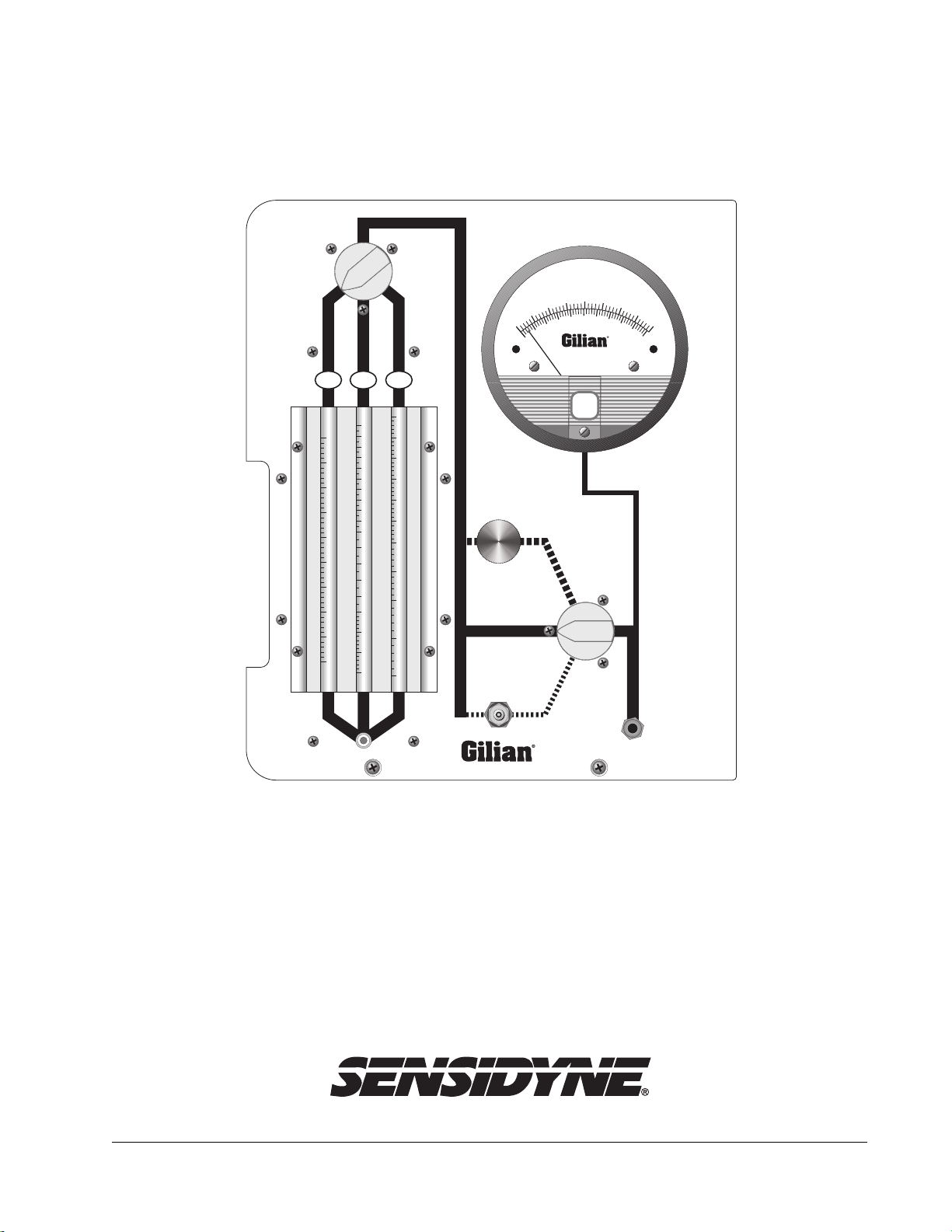
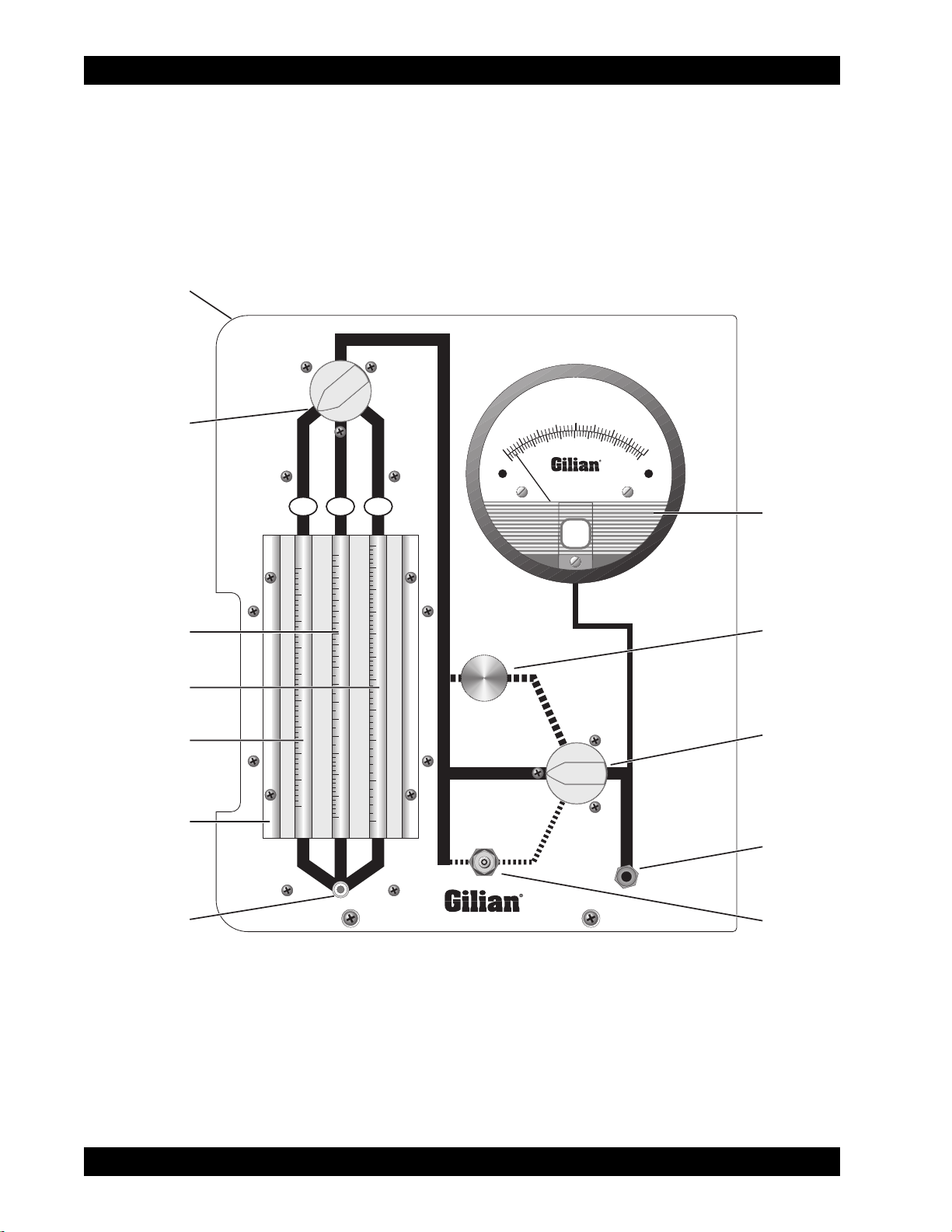
1.3.2 Triple-Flowtube Configuration:
Refer to Figure 2. In the triple-flowtube configuration,
air enters the panel through (B1), (B2) or (B3) and, as
directed by “Flow Selector Valve” (V2), passes through
“FM1”, “FM2” or “FM3”. It is then bypassed or applied
to the inlet valves (V3) or (V4) as directed by the posi-
tion of the Load Selector Valve (V1). Air leaves the
Load Selector Valve and is directed to the Pressure
Gauge and leaves the panel via boss (B4). The panel
allows the operator to monitor pressure drops associ-
ated with specific sampling media and, in the pump di-
agnostic mode, allows complete pump performance
checkout.