Aerola Alatus-M User manual

Powered Sailplane
ALATUS – M
OWNER’S MANUAL
February 2008
AEROLA Ltd., 19 Tupoleva str., Kiev 04128 Ukraine tel. (+380) 44 443-78-85;
fax. (+380) 44 449-94-68; info@alatus.biz www.aerola.com.ua

ALATUS-M – Owner’s Manual
1
ALATUS-M is essentially a new ultralight soaring glider. Experience of a creation and serial
production of the rigged wing Phantom and new original design and processing ideas which have allowed
combining in it advantages of rigged wing and classical glider. ALATUS-M self-launches from a small
airfield and it is able to soar like a rigged wing in light conditions and microlift.
ALATUS-M possesses higher flight performances, fine controllability, good behavior in spin or stall
conditions. Glider is comfortable, ergonomic and safe for pilot over a flying condition. An obtainable
price and low operating expenses also are a great value for customers.
ALATUS-M is called to occupy the extensive niche existing between foot-launch machines and gliders.
For successful operation with ALATUS-M it should be studied this Owners Manual carefully in details
with limitations, warning and instructions. Full reading and comprehension of this manual is imperative
before the first flight.
WISH YOU PLEASANT FLIGHTS!
Aerola Team

ALATUS-M – Owner’s Manual
2
RECORD OF REVISIONS
Rev.
No. Affected Section Affected Page Date of Revision

ALATUS-M – Owner’s Manual
3
CONTENTS
1. GENERAL 4
2. SPECIFICATIONS 6
3. LIMITATIONS 7
4. SUMMARY DESCRIPTION OF DESIGN AND SYSTEMS 9
5. ALATUS-M SETUP PROCEDURE 12
6. POWER PLANT OPERATION 30
7.PECULIARITIES OF TAXYING, TAKE-OFF AND LANDING 33
8. LOW-SPEED FLIGHT 34
APPENDIX No.1. ELECTRIC DIAGRAM 35

ALATUS-M – Owner’s Manual
4
1. GENERAL
1.1. SUMMARY DESCRIPTION OF POWERED SAILPLANE ALATUS-M
The powered sailplane ALATUS-M corresponds with an ultralight flying machine is controlled by a
manner of aerodynamic, which is made on modern technologies with wide application of composite
materials. Being available a retractable power unit allows it to self-launch and to climb although the glider
is permitted to aerotow by flexwing microlight or fixed-wing ultralight; glider on this case is equipped by
the towing hook.
Flight specifications and flight-navigation instruments provide of flights in daylight and in simple
weather conditions.
Landing gear and thrust/weight ratio allow to take-off/landing from an airfield with concrete, ground or
grass covering at minimum sub-soil strength of 0,3 MPa (3 kg/cm2).
The sailplane power unit is equipped by engine of CORS - AIR M25Y ‘BLAK DEVIL’.
Sailplane general overview with engine of CORS - AIR M25Y ‘BLAK DEVIL’ is shown in Fig.1
below.
1.2. WARNING, CAUTIONS AND NOTES
The following definitions apply to warning, cautions and notes used in the Owners Manual:
WARNING: means that the non-observation of the corresponding procedure leads to an immediate or
important degradation of the flight safety.
COUTION : means that the non-observation of the corresponding procedure leads to a minor or to a
more or less long term degradation of the flight safety.
NOTE : draws the attention on any special item not directly related to safety but which is
important or unusual.

ALATUS-M – Owner’s Manual
5
Fig.1. Glider overview.

ALATUS-M – Owner’s Manual
6
2. SPECIFICATIONS
2.1. DIMENSIONS DATA
Length 6,5 m
Height 1,16 m
Wing span 13,1 m
Wing area 13,2 m2
Aspect ratio 13,3
Deflection angels:
- ailerons up 25° down 15°
- flaps up 0° down 70°
- elevator up 25° down 15o
- rudder left 30° right 30°
Cockpit: height / width 0,85 / 0,61 m
Transporting overall dimensions:
- wing 5,9 х0,64 х0,4 m
- cockpit 2,9 х0,6 х0,9 m
2.2. WEIGHT DATA
Empty weight (without rescue system GRS 225 )
112+ 2% kg
Maximum take-off weight 235 kg
Minimum take-off weight 180 kg
Pilot weight range 60 – 110 kg
Wing loading 13,6 - 17,8 kg/m2
2.3. FLIGHT PERFOMENCES
M0=180kg M0=235kg
Maximum L/D ratio 27 27
Maximum L/D ratio speed 60 km/h 67 km/h
Minimum rate of descent 0,6 m/s 0,65 m/s
Minimum rate of descent with extension power-plant 1,6 m/s 1,6 m/s
Economic speed 50 km/h 56 km/h
Rate of descent at full extended flaps (at cruising speed ) 2,3 m/s 2,5 m/s
Stall speed 42 km/h 48 km/h
Take-off distance, ground airfield with grass covering 80 m 100 m
Lift-off speed 55 km/h 60 km/h
Take-off distance from rest to attaining a height of 15 m 260 m
Landing run, ground airfield with grass covering 30 m
Landing run from attaining a height of 15 m to rest,
ground airfield with grass covering 190 m
WARNING! INDICATED SPEEDS ONLY ARE GIVEN IN MANUAL

ALATUS-M – Owner’s Manual
7
2.4. POWER- PLANT DATA
Engine CORS-AIR M25Y ‘BLACK DAVIL’
Take-off condition (up to 3 min.):
- power 21 HP
- maximum rotational speed 7500 RPM
- fuel consumption 2,5 - 4,0 l/h
Sparking plug GK BR9ES 1
Fuil – petrol with 98 octane
Lubrication – fuil/oil mixture, mixing proportion 1:50, at hot-day conditions 1:45.
Synthetic oil SUPER-TWO-
STROKE
Fuil capacity 5,5 liters
Reducer driving ribbed belt
- reduction ratio 2,58
Cooling air
Propeller pulling
- blade 2
- rotating direction right
- diameter 1,2 m
3. LIMITATIONS
3.1. POWERED SAILPLANE LIMITATIONS
Maximum take-off (landing) weight 235 kg
Maximum forward CG position 20 % MAC*
Maximum rearward CG position 32 % MAC*
Maximum maneuvering load factors (flying weight 235 kg) +4 / -2
Maximum indicated flying speed:
Maximum flying speed 130 km/h
- rough air speed 96 km/h
- at full extended flaps 96 km/h
Maximum aerotow speed 96 km/h
Maximum wind speed at level ground:
- headwind 10 m/s
-
crosswind
5 m/s
- fair wind 3 m/s
Minimum take-off distance from rest to attaining a height of 15 m
(at take-off weight 235kg ) 260 m
* 20%MAC - 0,2b Mean Aerodynamic Chord
WARNING!ALATUS-M IS UNMANOEUVRED POWERED SAILPLANE. EXCEEDING
FLYING MANOEUVRE LIMITATIONS ARE PROHIBITED.
WARNING! FLYING ON ICING AREA IS PROHIBITED.

ALATUS-M – Owner’s Manual
8
WARNING!ADVANCED AEROBATIC MANOEUVRES ARE PROHIBITED. SIMPLE
AEROBATIC MANOEVRES ARE PERMITED (spin, slip, steep climb etc.).
WARNING! POWERED SAILPLANE ABUSE CAN BREACK FLIGHT SAFETY
APPRECIABLY.
3.2. POWER-PLANT LIMITATIONS
Fuil tank 5,6 liters
Engine continuous running time:
- take-off condition up to 3 min
- idle condition (at 2000 RPM) up to 5 min
- rest condition unlimited
Maximum cylinder head temperature 200°С
Operation temperature, + 40 ... –
10 °С
WARNING!CORS-AIR M25Y HAS NOTHING AIRWORTHNESS CERTIFICATE AND HAS
NOT BEEN TESTED ON MEETING WITH AIRWORTHNESS REQUIREMENTS. PILOT MUST
KNOW THAT ENGINE CAN FAIL IN FLIGHT THEREFORE FLYING THIS ENGINE IS DONE
ENTIRELY UNDER PILOT’S OWN RESPONSIBILITY AND RISK.
WARNING!THERE ARE NO ANY MECHANICAL IMPURITIES IN FUIL.
WARNING! FOR ENGINE GREASING PURPOSE APPLIES ONLY SYNTETIC BASED OIL.
NO USE ETHYLATED PETROL.
WARNING! DON’T USE MIXTURE OF VARIOUS OIL TYPE.
WARNING! NOT RECOMMENDED TO USE FUIL/OIL MIXTURE AFTER LONG STORAGE.
3.3. RESCUE SYSTEM LIMITATIONS
Minimum rescue system opening height of GRS- 225 or ALPHA 500 50 m

ALATUS-M – Owner’s Manual
9
4. SUMMARY DESCRIPTION OF DESIGN AND SYSTEMS
4.1. CONTROL SYSTEMS
The control system of powered sailplane consists of the joy stick, adjustable pedals according to pilot's
height, combined push-pull/cable control systems (links, cables etc.), rudder, elevator and ailerons. The
control of the adjustable pedal (blue) is on the central panel more to the right. Near the control stick (at left
below) a trimmer spring is located. Moving it forward increases a balancing speed, backwards reduces.
The flap lever is located on the cabin wall to the left it has two fixed positions:
#1 removed flaps (flap angle - 00). The flap lever is in fixed position PUSH TO STOP;
#2 extended flaps (flap angle - 200). A flap lever is in fixed take-off position. The further flaps
extending (PULL TO STOP up to 700) needs for growing a gliding angle at level landing.
4.2. POWER-PLANT
The retractable power-plant into the rear fuselage cover (engine bay) includes each component that the
engine with ribbed belt reducer, pulling propeller and exhaust system which installed on the carbon
column.
The engine carbon column are fastened by means of the rubber shock absorbers to the lower carbon
engine mount which activated by a linear actuator. In whole with the fuel tank and engine controls are
assembled on a welded frame.
An engine ignition system, fuil system, decomressor and the prop locking device are related to a power-
plant functionally which allow to fix the propeller in vertical position during retracting.
4.2.1. CORS-AIR M25Y (BLAK DEVIL) is petrolic, two-strokes, one-cylinder and air cooling
engine with the petal-type inlet valve, carburetor mixture formation, with the unduplicated electronic
ignition system which is equipped by resonance exhaust system.
An engine control is occurred by
1) the throttle lever with pilot's left hand it position PULL TO STOP is idle and it position PUSH TO
STOP is take-off. Moving the throttle lever changes of a butterfly position by means of the cable;
2) the switches on the control panel. The engine control panel is located on the left wall of the cockpit.
There is Master Switch, Ignition Switch, button of START, Retraction/Extension 3-position Switch and
Position Indicators (green and red) on the control panel.
Engine is started by means of the Ignition Switch and button of START.
Engine is stopped by means of Ignition Switch ONLY.
The linear actuator is driven by Retraction/Extension 3-position marked Switch. Green Position
Indicator lights in extension position; red indicator does in retraction position or in-between position.
The engine starting has been blocked when the engine does not retract out of the engine bay fully or
propeller is locked.
Before retracting the engine into the engine bay the propeller should be fixed exactly in vertical position
provided by the prop stop locking device. The propeller is turned over by hand on the ground and by
airflow in the flight until stopped. There is a decompressor for the propeller autorotation.
Locking of the prop locking device and opening of the decompressor valve are carried out by the
control levers located on the cockpit wall to the right. Both of the control levers are united while the
propeller locking the decompressor valve opens automatically.
4.2.2. The fuel system consists of a fuel tank, a filter, lines and fittings. There is a fuel nipple, fuil
quantity indicator and tank filler on the fuil tank.
Unusable fuel is 0,1 liter.

ALATUS-M – Owner’s Manual
10
WARNING! INLET AND OUTLET OF FUEL FILTER IS MARKED BY ARROW AND SHOULD
COORDINATE WITH FUEL FLOW.
4.2.3. The power supply is provided by the battery with 6-7 A.h capacity and controlled by the
Master Switch. Airborne voltage is DC 12 V. The battery charging is occurred by the generator coil during
the engine running by means of the relay-switch (Electric Diagram gives in Appendix No.1).
Battery storage is under the cockpit floor and closed marked cover.
4.3. LANDING GEAR
The landing gear is a bicycle type:
- a nose wheel size is 200х50 mm;
- a mane wheel size is 260х85 mm;
- a tire pressure into the nose and main wheel is 2,5 bar.
There are two rollers on the wing tips and one roller on the rear of the tail beam.
4.4. BRAKE SYSTEM
The wheel brake with cable system is power brake. There is a brake handle on the sailplane joy stick.
4.5. VENTILATION SYSTEM
The ventilation system prevents the misting of the canopy. Airblow is regulated by the handle located
under the instrument panel.
4.6. SEAT AND SAFATY HARNESS SYSTEM
The harness system consists of standard and shoulder belts. The harness lock is quick-release and conical
one. The backrest angle and pilot’s height position of the seat-back is adjustable. For flights with a
parachute the seat-back pillow is removed.
4.7. TOWING LOCK
The towing lock is installed in the forewheel well. The towing lock handle (yellow) is located on the
central panel to the left. If the angle between towing cable and centerline exceeds 900, the towing lock
releases the towing cable automatically.

ALATUS-M – Owner’s Manual
11
4.8. FLIGHT AND NAVIGATION INSTRUMENTS
The instrument panel is installed on the canopy frame and connected to static pressure system with
hermetic pipe connections (Pstat. and Рdin.) which is fastened by screw.
On the instrument panel are installed
air-speed indicator;
altimeter;
variometer;
magnetic direction indicator (option);
mirror for control of retraction/extension position.
Flight and navigation instruments can be changed by customer.
The engine functioning is checked out with an electronic controller with tachometer, voltmeter and timer
which places on a central panel below the towing lock handle.
Instrument location on the panel is shown below:
ALATUS-M – Owner’s Manual
12
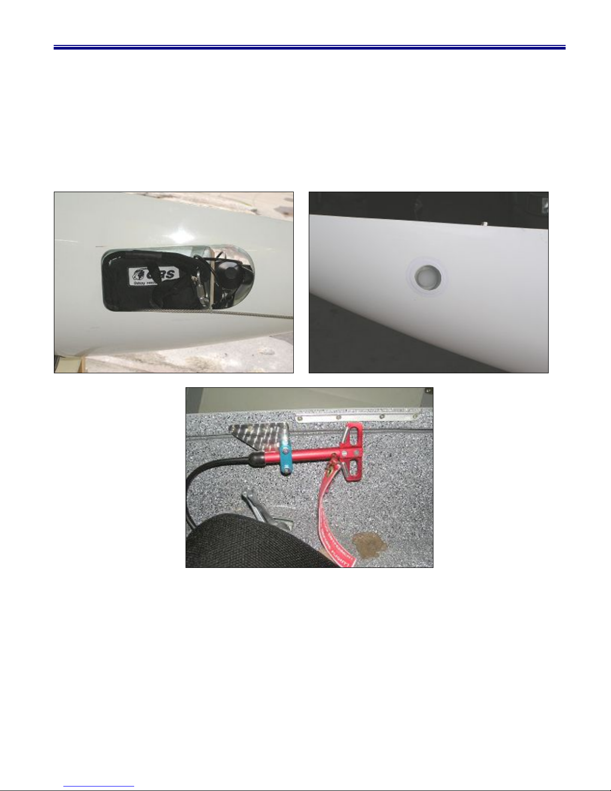
4.8. RESCUE SYSTEM
For the purpose of an emergency rescue in flight level a parachute rescue system of GRS 225 or
Alpfa-500 is installed which providing a landing of machine together with a pilot. The description of a
parachute rescue system is presented in Instruction Manual for Assembly and Use. The launching handle
is located on the cockpit wall to the right and painted in red, a handle is secured by the peg with the
warning red flag. The safety peg must be removed only when the aircraft is ready for take-off, and re-
inserted immediately upon completion of every flight.

ALATUS-M – Owner’s Manual
13
5. ALATUS-M SETUP PROCEDURE
5.1. Sailplane rigging.
5.1.1. Unzip the bag and put the wing/tail beam package out.
5.1.2. Set up the low rigging support under the wing/tail beam package about 1.5 m away from
the front side.
5.1.3. Spread the D-Cell apart 1.5m from the tail beam. Remove the tail beam bags out. Set up
the control arms of ailerons, elevator and rudder in neutral position.

ALATUS-M – Owner’s Manual
14
5.1.4. Remove the cockpit bag out. Remove the foreign subjects away from the cockpit.
Check a pressure into the nose and main tires. (P= 2,5 bar). Before checking the nose
wheel fairing mast be removed.
5.1.5. Set the trimmer spring up in neutral position. Set the joy stick and pedals up in neutral
position.

ALATUS-M – Owner’s Manual
15
5.1.6. Pull the pins out from the cockpit main joins (2 pins on the mane wall; 1 pin on the rear
wall). Approach the cockpit upwards to the wing until matching the main joins with the
tail beam joins. Remove the low rigging support, pull down the tail beam, and push the
pins in holes and lock them with loops of bungee.
5.1.7. Having moved the control stick and pedals make sure that the control system was
connected correctly. Spread the wings out fully until they stop and set the high rigging
supports up under the wings.
5.1.8. Unzip the bottom sail at a middle part.

ALATUS-M – Owner’s Manual
16
5.1.9. Attach the right strut (R) installing the Ball Lock Pin into the wall bracket then moving
the wing back and forth matching the strut with the tail beam plate. Install the tapered
pin and lock it by the still ring. Repeat all steps on the other side the same way. Make
sure that the control cable and the rib cable routes ABOVE the strut.
5.1.10. Remove the Velcro around the D-Cell and carefully pull the sail over the D-Cell. Go
to the wingtip. Reach inside the sail and locate the wire (red) that’s attached to the rib
safety cable. Pull that cable out of the sail and hook the loop of bungee over the tip pin
at the end of the D-Cell. Push the ribs into contact with the Trailing Edge Tube. Be
sure that they are properly aligned so the sail doesn’t get damaged. The bungee
tension should hold them nicely in place. Verify that the ribs are aligned properly,
connect the rib safety cable to the bracket located on the wall of the D-Cell.

ALATUS-M – Owner’s Manual
17
5.1.11. Pull the socket on the Trailing Edge Tube into alignment with the fitting and install he
Ball Lock Pin. Make sure that the flap spike slips into the hole in the arm located on
the cockpit.
5.1.12. Reach in the aileron pushrod through the aileron rib access.
5.1.13 Remove the tip sections from the bag. Align the tip section with the hooks on the
D-Cell and using a back and forth motion, wiggle the tip into place. Be sure the sail is
not caught in the assembly. Once the tip is in place, while holding it forward, rotate
the ears toward the inboard section of the D-Cell until they are fully parallel with the
wall of the D-Cell. You will hear a “snap” as they lock into place.

ALATUS-M – Owner’s Manual
18
5.1.14. Open up the carbon rib on the tip section and put the spike on the Trailing Edge Tube
into the hole in the carbon rib.
5.1.15. Pull the tip section of the sail out from inside the body of the sail. Open the Sail Clamp
by pulling the spring loaded bolt toward the cockpit. Zip and Velcro the sail around
the sail clamp.

ALATUS-M – Owner’s Manual
19
5.1.16. Close the Sail Clamp making sure that the spring loaded bolt is fully pushed closed and
there are no wrinkles in the sail. It will be VERY tight.
5.1.17. Rotate the tip section rearward enough to slip the grommets on the upper and lower
surface over the pins on the tip section.
5.1.18. Open the Trailing Edge Clamp all the way. Slip the hole in the inboard end of the
Trailing Edge Clamp over the spike of the Trailing Edge Tube.
Table of contents


