AEROPLANE HEAVEN Cessna 140 User manual

is Cessna 140 Cockpit and Flying
guide has been produced to make getting
acquainted with your new Cessna, both
simpler and more fun. To this end, this is not
an “ocial” pilot’s manual and should not be
considered such.
e Cessna 140 is a very simple little
aeroplane with few if any vices and is ying
in its purer, more basic form. So don’t go
expecting sophisticated systems, the very
latest avionics and navigation aids or any
computerised gizmos - as a 140 owner,
you have no need of such things.
What we have done, as you will
discover, is add a few modern comforts for
those wishing to do longer cross-country
ights using more modern navigation
processes.
Your Cessna is tted with a period
“Altimatic” auto-pilot. Not the most reliable
of instruments in its day, nor that stable in
operation, but we had one lying around the
workshop so we installed it to see how she
goes.
We won’t be teaching you how to y,
that is not the purpose of this guide. We are
going to assume that you have a good work-
ing knowlege of ight simulators and ying
in them. All the controls on the 140 are
easy to use and laid out in a sensible orderly
fashion, reminiscent of the motor-cars of the
1940s. On that note, we hope that you will
agree that the instrument panels are very
attractive and show a strong “art-deco”
heritage in their design. e cockpit of a 140
is just a “nice place to be”.
Well, let’s dive in and see what we have
in our shiny new aeroplane.
Power Plant:
One 85-hp or 90-hp Continental
four-cylinder horizontally-opposed air-
cooled engine driving McCauley xed-
pitch metal airscrew.
Fuel capacity 25 U.S. gallons (94 liters)
Accommodation:
Enclosed cabin seating two side-by-
side with dual controls.
Baggage allowance 80 lb (36 kg).
Weight empty: 900 lb (409 kg)
Weight loaded: 1,500 lb. (680 kg)
Performance:
Maximum speed: 120-125 mph
Cruising speed: 105 mph
Landing speed: 41 mph
Rate of climb: 680 fpm
Service ceiling: 15,500 ft (4,724 m)
Cruising range: 450 miles (724 km)
THE CESSNA 140 (details may
change depending on year and modi-
cations. Many examples were modied
to bring them up to modern standard.)
Wings:
Wing span: 32ft. 10ins. (10m)
Wing area: 159.6 ft² (14.8 m²)
Fuselage:
Monocoque all Alloy structure
Length (tail up): 20 ft 11? in (6.40 m).
Height (tail down): 6 ft 3¼ in (1.91 m)
Tail Unit:
Trim-tab in starboard elevator.
Tailplane span: 8 ft 10 in (2.69 m).
Landing Gear:
Cessna patented xed sprung steel
Hydraulic friction-disc brakes.
Track: 6 ft 5 in (1.96 m)
Scott steerable tail-wheel.
Twin Edo Model 1650 oats (optional)
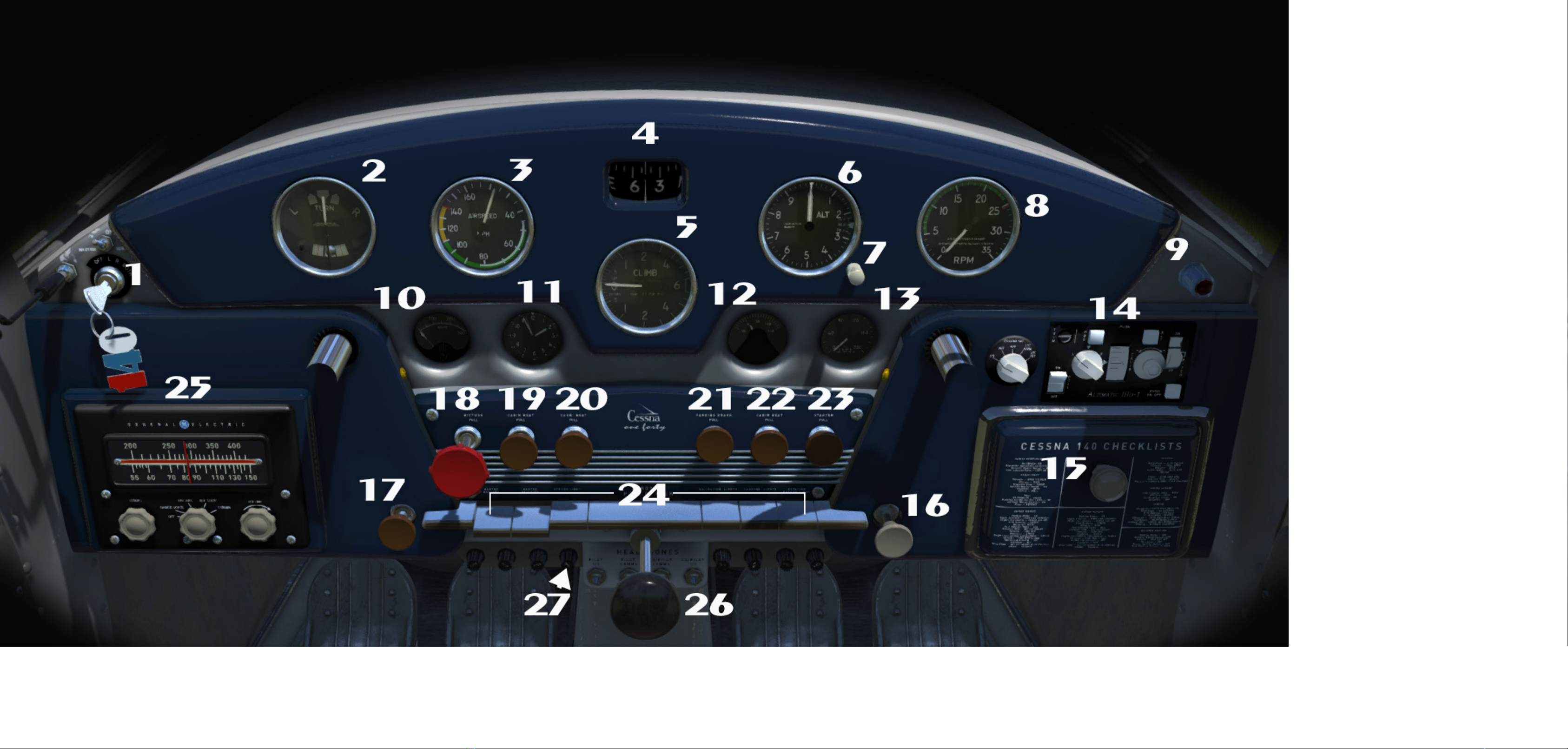
What’s so nice about the C140’s panel
is that everything is laid out in a sensible,
orderly fashion with everything immediately
to hand. It doesn’t take long to familiarise
yourself with the controls and instruments.
e panel is divided into four main
sections. e ying instruments are grouped
in the main panel arcing right across the
cockpit. Immediately below in a sub pan-
el are the “systems” gauges for engine and
electrics and a handy clock. Below this again,
the major operating controls are grouped
together in a neat centre panel.
A “piano keyboard” of electrical
switches is mounted below with a big central
throttle control dominating the area.
Below all of this are the circuit breaker/fuses
and a small jack panel for microphones and
accessories.
Flanking the centre panel are two
quarter panels. One houses the air radio set,
the other, the Altimatic AutoPilot (wow!)
and a special addition we installed to assist
with cross country navigation. is takes the
form of an HSI instrument which is accessed
by clicking on the “sandwich box lid” of the
compartment. We’ll discuss this later.
In the bottom le corner of this panel
is a cream knob. Pull this to toggle on the
tiedowns and chocks. Toggle on the pilot and
passenger by using the big centre piano key.
1. Magnetos 2. Turn/Slip Indicator 3. Airspeed Indicator 4. Gyro Compass 5. Climb/Fall Indicator (VSI) 6. Altimeter 7. Kholsman adjuster 8. Tachometer 9. Stall Indicator light 10. Ammeter
11. Clock 12. Oil Temperature 13. Oil Pressure 14. Altimatic (AutoPilot) 15. HSI (hidden) 16. Secure Aircraft Toggle 17. Engine Primer 18. Mixture control 19. Cabin Heater 20. Carburettor Heater
21. Parking Brake 22. Cabin Heater (2) 23. Engine Starter 24. Electrical (From left- Master Battery - Avionics Master - Strobe Light (when tted - ours isn’t) - Toggle for pilots - Navigation Lights -
Landing Lights- Rotating Beacon Light 25. Radio Receiver 26. Throttle 27. Hide/Show Yoke toggle
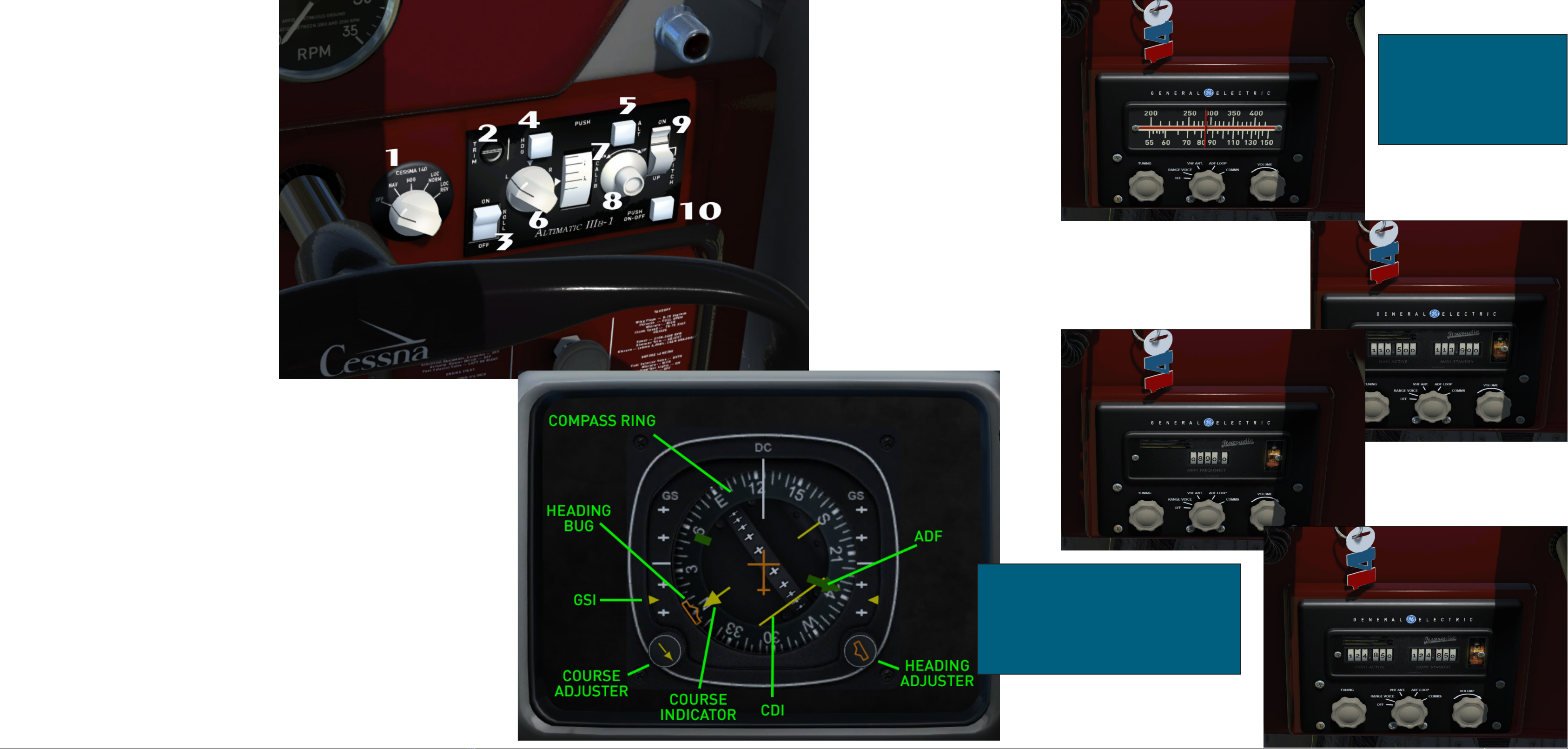
Instructions for use of the
Altimatic IIIB AutoPilot
Turn on the unit by the Master Power
Switch (10) e main function control (1)
allows you to set the Altimatic to obey in-
puts from a variety of sources. From le to
right, these functions are: OFF, NAV(hold
mode) when radio frequencies are set and
the NAV1 radial is acquired, in this mode,
the Altimatic will steer the aircra to that
radial. HDG (heading hold mode) in this
mode the Altimatic will hold the aircra on
the heading set by the HSI. LOC/NORM
(ILS approach mode) when an aireld local-
iser is acquired this mode will steer and hold
the aircra on the correct lateral approach,
of course vertical attitude on the glideslope
must be adjusted manually – this is not a
“land-me” system! LOC/REV (Back course
mode) is used when the radial has been
overown or you are moving away from the
radial.
Using the Roll switch (3) activates the
wing leveler system. Whenever NAV,LOC or
HDG modes are used, this switch MUST be
OFF. In HDG (heading hold) mode, the
Altimatic will obey commands from the
Heading selector /adjust knob on the HSI
and y the aircra on that heading.
Adjustments can be made in this
mode by using the Turn Knob (6).
Altitude can be set and held in the
Altimatic by setting the desired altitude
using the Altitude Selector Knob (8) and the
rotational scale (7) Once desired altitude is
set, push the Altitude Hold knob (5) to ac-
tivate the autopilot Alt/Hold function. Ad-
justments can be made to the vertical speed
whilst in Alt/Hold mode, by using the Pitch
Trim Knob(9).
Operating the HSI
First click on the locker lid cover to
rotate it and reveal the HSI unit. is is
modeled on a modern unit found in much
later Cessnas. It consists of a compass rose
with a lubber line, a CDI (Course Deviation
Indicator) and a GSI (GlideSlope Indicator).
e two knobs allow for course and
heading settings to be made with an orange
heading “bug” and a yellow course indicator.
Our HSI has a white NAV1 and a
green ADF needle added (there’s no RMI).
ere are many useful publications
available on the web which cover the use of
an HSI in detail. ey are quite easy to use
despite their complex appearance.
Used in conjunction with the
Altimatic IIIb, you now have a fairly
sophisticated navigation setup - especially
for a Cessna140!
Using the Radio Set.
ere are three large knobs mounted
on the radio panel. e centre one selects
the type of radio you wish to use - COMMS,
NAV1 or ADF1. It also turns on the radios,
switching out from the blank “false” panel to
the working panels. To turn on the radio set,
RIGHT CLICK the centreknob. You need to
do this TWICE as it will cycle to the “Range
Voice” segment rst. Right click again and
you’ll bring up the NAV1 Radio. Again and
you’ll have the ADF Radio and nally, the
COMMS Radio. e NAV and COMMS
radios have two windows, the le is the
ACTIVE and the right, STANDBY
frequencies. e right hand knob will switch
between the two. e ADF has just one
window as there is no standby frequency.
To tune frquencies, use the le knob,
using a combination of le and right click
and wheel. Do the same for the ADF frquen-
cy. Please note: e simulator is built to use
separate knobs one knob is a little tricky but
you’ll soon get the hang of it. Once properly
tuned, the frequencies will interact with your
HSI so you can set up for IFR navigation.
Red “flags” will appear, occasionally, in the
window of the HSI. These are warning flags
to tell you that the NAV radio is off or off
frequency or that HEADING HOLD is un-
available. These flags also appear when the
AVIONICS ARE OFF
ALWAYS REMEMBER TO
HAVE YOUR BATTERY
SWITCHED ON AND THE
AVIONICS MASTER SWITCH
KEY PRESSED (24) BEFORE
USING THE RADIO.

Setting up for a ight.
ere are a couple of optional extras
that come with your Cessna 140. ere’s a set
of chocks and tie-downs which are toggled
on and o using the knob (16). Pilots are
toggled on and o using the large central
piano key switch (24).If you are ying in
P3DV4.4 and up, you can congure your
undercarriage to have wheel spats. All you
need to do is click on the undercarriage strut
in the outside view.
ere are two fuel gauges - one for the
le wing tank and one for the right. ey are
located in the wingroot of each wing , just
inside the top corners of the windscreen.
e dials have a red segment which indicates
low contents. On no account attempt to take
o with the needles inside these red areas.
Always check that you have sucient fuel
before making a ight. e Cessna 140 is
very economical on fuel but will eventually
run out of the stu.
On the oor, immediately in front of
the seats there is a fuel tank selector. It oper-
ates with LEFT and RIGHT CLICK to select
either or both tanks.
ere is an elevator trim tab which is
controlled by a large rubber rimmed wheel.
e amount of up or downward trim is in-
dicated by a white pointer. Red markings on
the side of the trim unit indicate the recom-
mended position for trim for takeo. Set it
up so that the pointer is within the red range.
e Cessna 140 likes to be a tad nose down
for takeo.
A of the trim unit is the aps handle.
Pulling this straight up will actuate the aps.
e Pull ring device is the WATER
RUDDER control and obviously, is only ever
used when oats are tted.
NEVER TAKE OFF WITH THE
FUEL GAUGE NEEDLES IN
THE RED AREAS!!
NOT ONLY WILL YOU RUN
OUT OF FUEL BUT YOUR
AIRCRAFT WILL BE
UNBALNCED AND MAY
PROVE HARD TO HANDLE.
Other AEROPLANE HEAVEN Aircraft manuals


