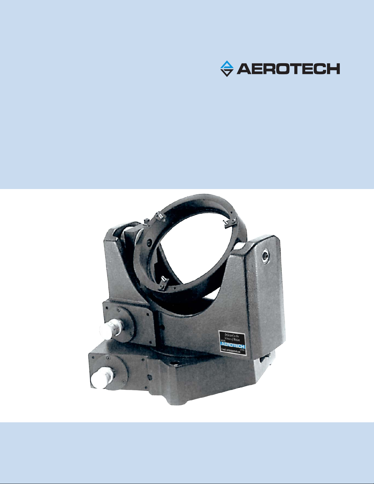
Table of Contents AOM130 User Manual
Safety Procedures and Warnings
This manual tells you how to carefully and correctly use and operate the AOM130. Read all parts of this
manual before you install or operate the AOM130 or before you do maintenance to your system. To prevent
injury to you and damage to the equipment, obey the precautions in this manual. The precautions that follow
apply when you see a Danger or Warning symbol in this manual. If you do not obey these precautions, injury
to you or damage to the equipment can occur. If you do not understand the information in this manual,
contact Aerotech Global Technical Support.
This product has been designed for light industrial manufacturing or laboratory environments. The protection
provided by the equipment could be impaired if the product is used in a manner not specified by the
manufacturer.
N O T E : Aerotech continually improves its product offerings; listed options may be superseded at any
time. All drawings and illustrations are for reference only and were complete and accurate as of this
manual’s release. Refer to www.aerotech.com for the most up-to-date information.
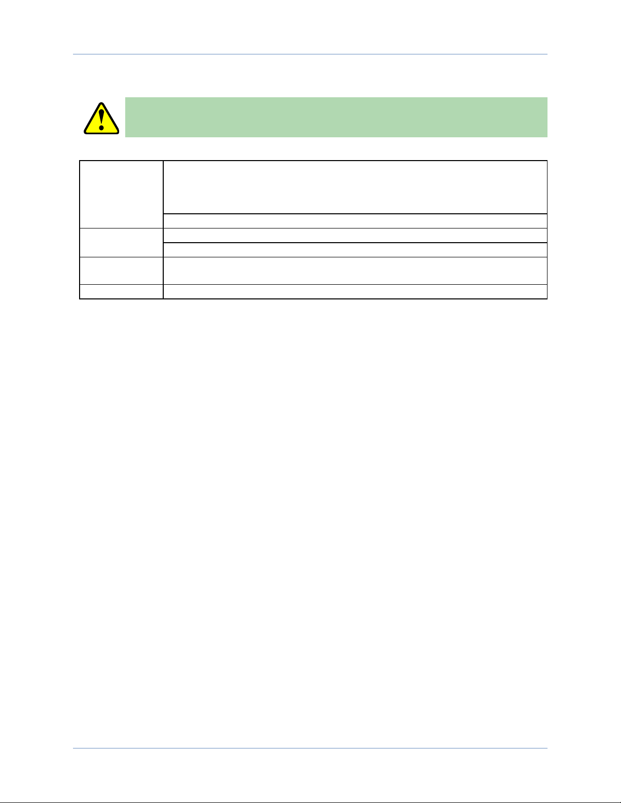
W A R N I N G : To minimize the possibility of injury or damage to the equipment, the following
precautions must be followed.
1. Do not expose this product to environments or conditions outside of the listed
specifications. Exceeding environmental or operating specifications can cause damage to
the equipment.
2. The AOM130 must be mounted securely. Improper mounting can result in injury and
damage to the equipment.
3. Use care when moving the AOM130. Lifting or transporting the AOM130 improperly can
result in injury or damage to the AOM130.
4. If the product is used in a manner not specified by the manufacturer, the protection
provided by the product can be impaired and result in damage, shock, injury, or death.
5. Operators must be trained before operating this equipment.
6. All service and maintenance must be performed by qualified personnel.
6 www.aerotech.com