Aerotech AMG Series User manual

Revision 2.00
AMG Series Motorized Position and
Rate Gimbals
HARDWAREMANUAL

GLOBALTECHNICALSUPPORT
Go to the Global Technical Support Portal for information and support about your
Aerotech, Inc. products. The website supplies software, product manuals, Help files,
training schedules, and PC-to-PC remote technical support. If necessary, you can
complete Product Return (RMA) forms and get information about repairs and spare
or replacement parts. To get help immediately, contact a service office or your sales
representative. Include your customer order number in your email or have it
available before you call.
This manual contains proprietary information and may not be reproduced,
disclosed, or used in whole or in part without the express written permission of
Aerotech, Inc. Product names mentioned herein are used for identification purposes
only and may be trademarks of their respective companies.
Copyright © 2006-2022, Aerotech, Inc., All rights reserved.

Table of Contents
AMG Series Motorized Position and Rate Gimbals 1
Table of Contents 3
List of Figures 4
List of Tables 5
EU Declaration of Incorporation 6
UKCADeclaration of Incorporation 7
Safety Procedures and Warnings 8
Installation and Operation 9
Electrical Warnings 10
Motor-Related Warnings 11
Pinch Points 12
Handling and Storage 13
Chapter 1: Overview 17
1.1. Environmental Specifications 18
1.2. Accuracy and Temperature Effects 18
1.3. Basic Specifications 19
1.4. Vacuum Operation 20
1.5. Export Restrictions 21
Chapter 2: Installation 23
2.1. Dimensions 23
2.2. Securing the Base to the Mounting Surface 28
2.3. Attaching the Payload to the Stage 30
Chapter 3: Electrical Installation 31
3.1. Motor and Feedback Connectors 32
3.2. Motor and Feedback Wiring 35
3.3. Motor and Feedback Specifications 36
3.4. Limits, Marker, and Machine Direction 40
3.5. Motor and Feedback Phasing 41
Chapter 4: Maintenance 43
4.1. Service and Inspection Schedule 43
4.2. Cleaning and Lubrication 44
4.3. Troubleshooting 45
Appendix A: Warranty and Field Service 47
Appendix B: Revision History 49
Index 51
Hardware Manual AMG
www.aerotech.com 3

List of Figures
Figure 1-1: Shipping Brackets 14
Figure 1-2: Lifting Features 15
Figure 2-1: AMG200 Dimensions 23
Figure 2-2: AMG300 Dimensions 24
Figure 2-3: AMG400 Dimensions 25
Figure 2-4: AMG500 Dimensions 26
Figure 2-5: AMG600 Dimensions 27
Figure 2-6: View of AMG Showing Mounting Holes 29
Figure 3-1: AMGMotor and Feedback Wiring 35
Figure 3-2: Machine Direction 40
Figure 3-3: Hall Phasing Diagram 41
Figure 3-4: Encoder Phasing Reference Diagram (Standard/Square Wave) 42
Figure 3-5: Encoder Phasing Reference Diagram (Analog/Sine Wave) 42
AMG Hardware Manual
4 www.aerotech.com

List of Tables
Table 1-1: Model Numbers and Ordering Options 17
Table 1-2: Environmental Specifications 18
Table 1-3: AMGSeries Specifications 19
Table 2-1: Stage Mounting Surface Flatness Requirement 28
Table 2-2: Stage to Mounting Surface Hardware 28
Table 3-1: High Power D-Style Motor Connector Pinout 33
Table 3-2: Mating Connector Part Numbers for the Motor Connector 33
Table 3-3: Feedback Connector Pinout 34
Table 3-4: Mating Connector Part Numbers for the Feedback Connector 34
Table 3-5: Hall-Effect Sensor Specifications 36
Table 3-6: Thermistor Specifications 36
Table 3-7: Encoder Specifications 36
Table 3-8: Azimuth Resolution Information 36
Table 3-9: Elevation Resolution Information 36
Table 3-10: S-130-39 Rotary Motor Specifications 37
Table 3-11: S-180-69 Rotary Motor Specifications 38
Table 3-12: S-240-63 Rotary Motor Specifications 39
Table 4-1: Troubleshooting 45
Hardware Manual AMG
www.aerotech.com 5

EU Declaration of Incorporation
Manufacturer Aerotech, Inc.
101 Zeta Drive
Pittsburgh, PA 15238-2811
USA
herewith declares that the product:
AMG gimbal
is intended to be incorporated into machinery to constitute machinery covered by the Directive 2006/42/EC
as amended;
and that the following harmonized European standards have been applied:
EN ISO 12100:2010
Safety of machinery - Basic concepts, general principles for design
EN 60204-1:2010
Safety of machinery - Electrical equipment of machines - Part 1:General
requirements
and further more declares that
it is not allowed to put the equipment into service until the machinery into which it is to
be incorporated or of which it is to be a component has been found and declared to
be in conformity with the provisions of the Directive 2006/42/EC and with national
implementing legislation, for example, as a whole, including the equipment referred
to in this Declaration.
This is to certify that the aforementioned product is in accordance with the applicable requirements of the
following directive(s):
EU 2015/863 Directive, Restricted Substances (RoHS 3)
Authorized
Representative / Simon Smith, European Director
Aerotech Ltd
The Old Brick Kiln, Ramsdell, Tadley
Hampshire RG26 5PR
UK
Engineer Verifying
Compliance / Alex Weibel
Aerotech, Inc.
101 Zeta Drive
Pittsburgh, PA 15238-2811
USA
Date 12/20/2022
AMG Hardware Manual
6 www.aerotech.com

UKCADeclaration of Incorporation
Manufacturer Aerotech, Inc.
101 Zeta Drive
Pittsburgh, PA 15238-2811
USA
herewith declares that the product:
AMG gimbal
To which this declaration relates, meets the essential health and safety requirements and is in conformity
with the relevant UK Legislation listed below:
Supply of Machinery (Safety) Regulations 2008
Hazardous Substances in Electrical and Electronic Equipment Regulations 2012
Using the relevant section of the following UK Designated Standards and other normative
documents when installed in accordance with the manufacturer's supplied installation instructions.
EN ISO 12100:2010
Safety of machinery - Basic concepts, general principles for design
EN 60204-1:2010
Safety of machinery - Electrical equipment of machines - Part 1:General
requirements
and furthermore declares that it is not allowed to put the product into service until the machinery
into which it is to be incorporated or of which it is to be a component has been found and declared
to be in conformity with the provisions of the Supply of Machinery (Safety) Regulations 2008 UK
Legislation and with national implementing legislation, for example, as a whole, including the
equipment referred to in this Declaration.
EN ISO 12100:2010
Safety of machinery - Basic concepts, general principles for design
Authorized
Representative / Simon Smith, European Director
Aerotech Ltd
The Old Brick Kiln, Ramsdell, Tadley
Hampshire RG26 5PR
UK
Engineer Verifying
Compliance / Alex Weibel
Aerotech, Inc.
101 Zeta Drive
Pittsburgh, PA 15238-2811
USA
Date 12/20/2022
Hardware Manual AMG
www.aerotech.com 7

Safety Procedures and Warnings
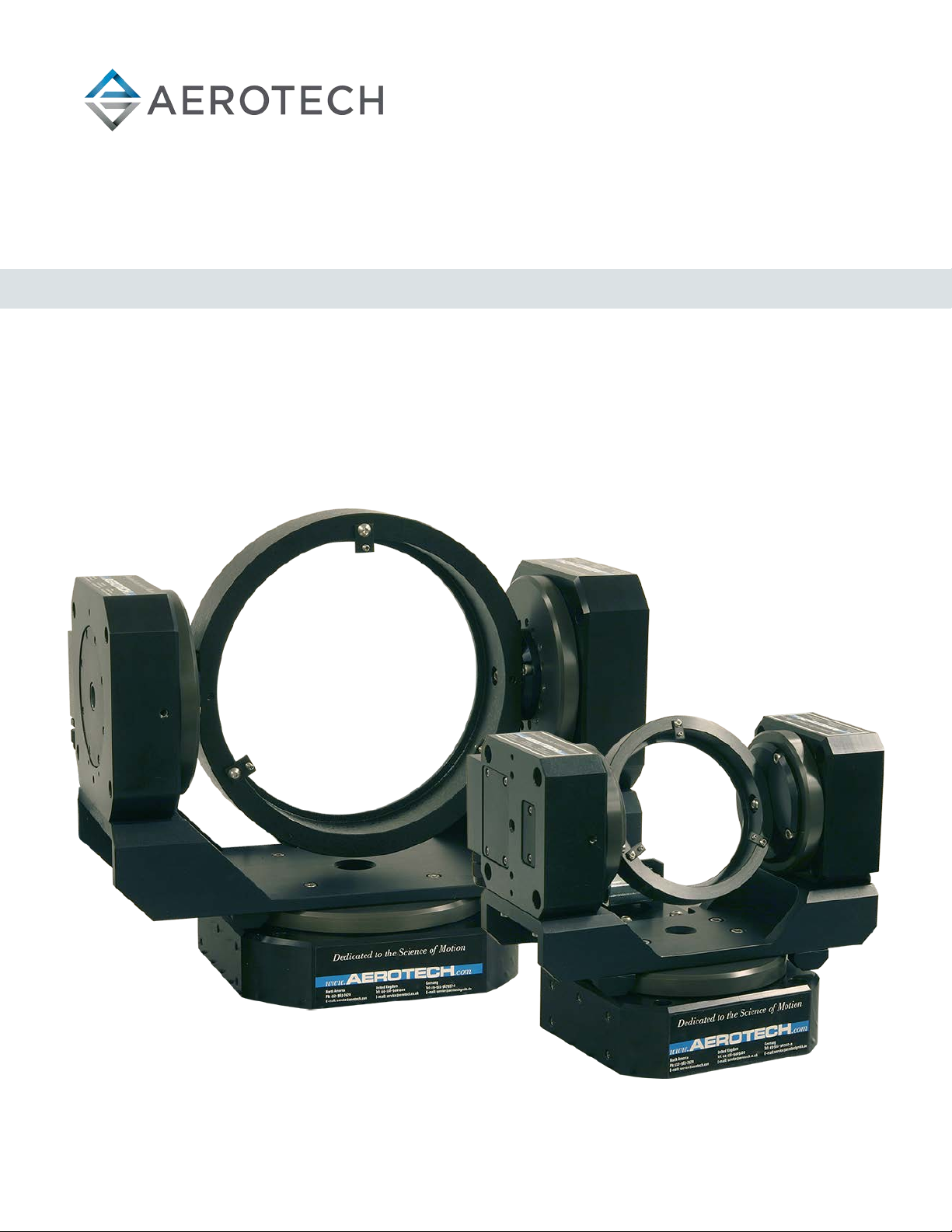
IMPORTANT: This manual tells you how to carefully and correctly use and operate the
gimbal.
lRead all parts of this manual before you install or operate the gimbal or before you
do maintenance to your system.
lTo prevent injury to you and damage to the equipment, obey the precautions in this
manual.
lAll specifications and illustrations are for reference only and were complete and
accurate as of the release of this manual. To find the newest information about this
product, refer to www.aerotech.com.
If you do not understand the information in this manual, contact Aerotech Global
Technical Support.
IMPORTANT: This product has been designed for light industrial manufacturing or
laboratory environments. If the product is used in a manner not specified by the
manufacturer:
lThe protection provided by the equipment could be impaired.
lThe life expectancy of the product could be decreased.
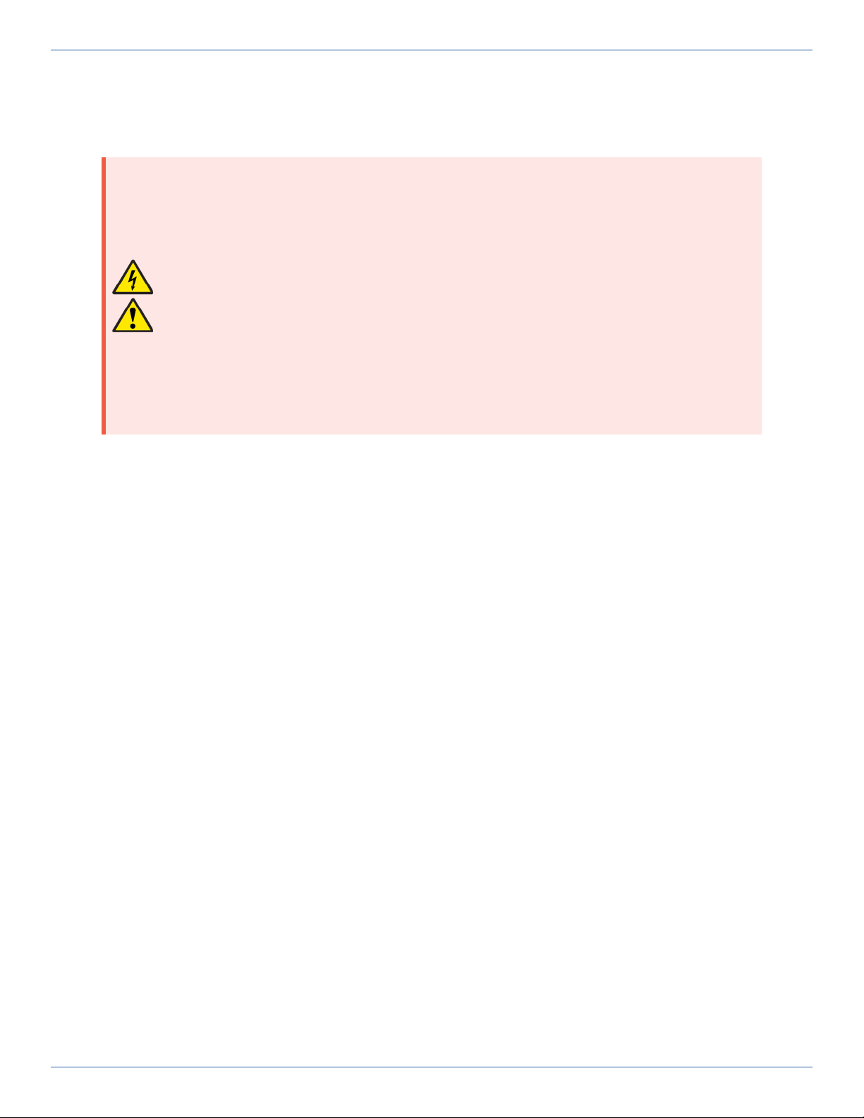
Safety notes and symbols are placed throughout this manual to warn you of the potential risks at the
moment of the safety note or if you fail to obey the safety note.
Shock/Electrocution Hazard Pinch, Shear, or Crush Hazard
General/Conditional Awareness Rotational Machinery Hazard
Hot Surface Hazard Pinch/Entanglement Hazard
Magnetic Field Hazard Trip Hazard
Heavy, Bulky Lifting Hazard Appropriate Equipment Required
Pressure/Explosive Atmosphere
Hazard Electrostatic Discharge Hazard
A blue circle symbol is an action or tip that you should obey. Some examples include:
General tip Read the manual/section
Wear personal protective equipment
(PPE): Safety Glasses If applicable, do not lift unassisted
Wear personal protective equipment
(PPE): Gloves
Wear personal protective equipment
(PPE): Hearing Protection
AMG Hardware Manual
8 www.aerotech.com

Installation and Operation
To decrease the risk of damage to the equipment, you must obey the precautions that follow.
DANGER: General Hazard Warning!
This product can produce high forces and move at velocities that could cause injury.
The user is responsible for its safe operation. The following general equation is
provided to assist with risk assessments in regards to contact and pinch points:
WARNING: General Hazard Warning!
lOnly trained operators should operate this equipment.
lAll service and maintenance must be done by approved personnel.
lUse this product only in environments and operating conditions that are approved in
this manual.
lNever install or operate equipment that appears to be damaged.
lMake sure that the product is securely mounted before you operate it.
lUse care when you move the AMG or you could negatively affect the performance of
it.
WARNING:Trip Hazard!
Route, house, and secure all cables, duct work, air, or water lines. Failure to do so could
introduce trip hazards around the system that could result in physical injury or could
damage the equipment.
Hardware Manual AMG
www.aerotech.com 9

Electrical Warnings
To decrease the risk of electrical shock, injury, death, and damage to the equipment, obey the
precautions that follow.
DANGER: Electrical Shock Hazard!
lStage motor phase voltage levels could be hazardous live.
lPersonnel are protected from hazardous voltages unless electrical interconnections,
protective bonding (safety ground), or motor/stage enclosures are compromised.
lDo not connect or disconnect stage/motor interconnections while connected to a live
electrical power source.
lBefore you set up or do maintenance, disconnect electrical power.
lIt is the responsibility of the End User/System Integrator to make sure that stages are
properly connected and grounded per Engineering Standards and applicable safety
requirements.
lIt is the responsibility of the End User/System Integrator to configure the system
drive or controller within the Aerotech motor/stage electrical and mechanical
specifications.
AMG Hardware Manual
10 www.aerotech.com

Motor-Related Warnings
Aerotech motors are capable of producing high forces and velocities. Obey all warnings and all
applicable codes and standards when you use or operate a stage or system that incorporates
Aerotech motors.
DANGER: Mechanical Hazard!
Personnel must be made aware of the mechanical hazards during set up or when you
do service to the stage.
lUnintentional manual movement into the stage "end-of-travel" stops, could damage
the stage or undo precision alignments.
lStage movement could create pinch points, entanglement hazards, or rotational
mechanical hazards.
DANGER: Hot Surface Hazard!
lThe stage/motor frame temperature could exceed 70°C in some applications.
lDo not touch the stage/motor frame while it is in operation.
lWait until the stage/motor has cooled before you touch it.
DANGER:Risk of Explosive Atmosphere!
lStandard Aerotech stage/motors are not rated for applications with explosive
atmospheres such as airborne dust or combustible vapors.
lDo not operate stage/motors outside of Aerotech environmental specifications.
DANGER: Magnetic Field Hazard!
Aerotech stage/motors contain magnets which can present a Magnetic Field Hazard.
lDo not disassemble a stage motor under any circumstances.
lStrong magnetic fields could interfere with external/internal medical devices.
lStrong magnetic fields could present mechanical hazards such as pinch points.
Hardware Manual AMG
www.aerotech.com 11

Pinch Points
A pinch point is a mechanical hazard that can occur when there are exposed parts of the stage or
system that can move. For example, the travel of a stage tabletop could expose the user to a pinch
point between the tabletop and the stage housing. The images that follow will show you typical
external and internal pinch point locations.
DANGER: Mechanical Hazard!
lSystem travel can cause crush, shear, or pinch injuries.
lOnly trained operators should operate this equipment.
lDo not put yourself in the travel path of machinery.
lRestrict access to all motor and stage parts
owhen the system moves under power (during normal operation, for example).
owhen the system is moved manually (during the installation process or when you
do maintenance, for example).
lMotors are capable of very high speeds and acceleration rates.
Figure 1: Typical Pinch Point Locations
AMG Hardware Manual
12 www.aerotech.com

Handling and Storage
IMPORTANT: It is the responsibility of the customer to safely and carefully lift and
move the gimbal.
lBe careful when you move or transport the gimbal.
lRetain the shipping materials for future use.
lTransport or store the gimbal in its protective packaging.
WARNING: Electrostatic Discharge (ESD) Sensitive Components!
Wear an ESDwrist strap when you handle, install, or do service to the system assembly.
You could damage the power supply or drives if you fail to observe the correct
ESDpractices.
Inspect the shipping container for any evidence of shipping damage. If any damage exists, notify the
shipping carrier immediately.
Remove the packing list from the shipping container. Make sure that all the items specified on the
packing list are contained within the package.
The documentation for the gimbal is on the included installation device. The documents include
manuals, interconnection drawings, and other documentation pertaining to the system. Save this
information for future reference.
Each stage has a label listing the system part number and serial number. These numbers contain
information necessary for maintenance or system hardware and software updates. Locate this label
and record the information for later reference.
Unpacking and Handling
It is the responsibility of the customer to safely and carefully lift and move the gimbal.
IMPORTANT: All electronic equipment and instrumentation is wrapped in antistatic
material and packaged with desiccant. Ensure that the antistatic material is not
damaged during unpacking.
DANGER:Lifting Hazard! Use care when you move the AMG or you could negatively
affect the performance of it.
lUse the correct lifting techniques, mechanical assistance, or additional help to lift or
move this product.
lDo not use the cables or the connectors to lift or move this product.
lMake sure that all moving parts are secure before you move the gimbal. Unsecured
moving parts could shift and cause injury or damage to the equipment.
lIf the gimbal is heavy, a single person lift could cause injury. Use assistance when you
lift or move it.
oRefer to Section 2.1. Dimensions for dimensions
Carefully remove the stagefrom its protective shipping container.
lLift this product only by the base.
lFor multi-axis assemblies, always lift the system by the lower axis.
lUse a cart, dolly, or similar device to move the stage to a new location.
Gently set the stage on a smooth, flat, and clean surface. Use compressed nitrogen or clean, dry, oil-
free air to remove any dust or debris that has collected during shipping.
Hardware Manual AMG
www.aerotech.com 13

Before you operate the stage, let it stabilize at room temperature for at least 12 hours. This will
ensure that all of the alignments, preloads, and tolerances are the same as they were when they
were tested at Aerotech.
Each stage has a label listing the system part number and serial number. These numbers contain
information necessary for maintenance or system hardware and software updates. Locate this label
and record the information for later reference.
Shipping Brackets
Shipping brackets (typically red, anodized aluminum) might have been installed to secure the system
prior to shipment. The shipping brackets, if installed, will need to be removed prior to machine start
up.
Figure 1-1: Shipping Brackets
AMG Hardware Manual
14 www.aerotech.com

Figure 1-2: Lifting Features
Storage
Store the gimbal in the original shipping container. If the original packaging included ESDprotective
packaging, make sure to store the gimbal in it. The storage location must be dry, free of dust, free of
vibrations, and flat.
Refer to Section 1.1. Environmental Specifications
Hardware Manual AMG
www.aerotech.com 15

This page intentionally left blank.
AMG Hardware Manual
16 www.aerotech.com

Chapter 1: Overview
Table 1-1: Model Numbers and Ordering Options
AMG Series Direct-Drive Gimbals
AMG200 200 mm nominal aperture
AMG300 300 mm nominal aperture
AMG400 400 mm nominal aperture
AMG500 500 mm nominal aperture
AMG600 600 mm nominal aperture
Feedback (Required)
-E1 Incremental encoder, 1 Vpp
-E2 Incremental encoder, TTL, x5 interpolation
-E3 Incremental encoder, TTL, x50 interpolation
Metrology (Required)
-PL1 Metrology, uncalibrated with performance plots
-PL2 Metrology, calibrated (HALAR) with performance plots
Integration (Required)
-TAS Test as system: Testing, integration, and documentation of a group of components
as a complete system that will be used together.
-TAC Test as components:Testing and integration of individual items as discrete
components that ship together.
Hardware Manual AMG
www.aerotech.com 17

1.1. Environmental Specifications
WARNING:General Hazard Warning! Do not expose this product to environments or
conditions outside of the listed specifications. You could damage the equipment if you
exceed the environmental or operating specifications.
DANGER:Risk of Explosive Atmosphere!
lStandard Aerotech stage/motors are not rated for applications with explosive
atmospheres such as airborne dust or combustible vapors.
lDo not operate stage/motors outside of Aerotech environmental specifications.
Table 1-2: Environmental Specifications
Ambient
Temperature
Operating: 10° to 35° C (50° to 95° F)
The optimal operating temperature is 20° C ±2° C (68° F ±4° F). If at any time the
operating temperature deviates from 20° C degradation in performance could
occur.
Storage: 0° to 40° C (32° to 104° F) in original shipping packaging
Humidity Operating: 20% to 60% RH
Storage: 10% to 70% RH, non-condensing in original packaging.
The stage should be packaged with desiccant if it is to be stored for an extended
time.
Altitude Operating: 0 m to 2,000 m (0 ft to 6,562 ft) above sea level
Contact Aerotech if your specific application involves use above 2,000 m or below
sea level.
Vibration Use the system in a low vibration environment. Floor or acoustical vibration can
affect system performance. Contact Aerotech for information regarding your
specific application.
Protection
Rating
Limited protection against dust, but not water (IP40 equivalent ingress protection
rating).
Use Indoor use only
1.2. Accuracy and Temperature Effects
Aerotech products are designed for and built in a 20°C (68°F) environment. Temperature changes
could cause a decrease in performance or permanent damage to the gimbal. At a minimum, the
environmental temperature must be controlled to within 0.25ºC per 24 hours to ensure the gimbal
specifications are repeatable over an extended period of time. The severity of temperature effects
on all specifications depends on many different environmental conditions, which include how the
gimbal is mounted. Contact the factory for more details.
AMG Hardware Manual
18 www.aerotech.com

1.3. Basic Specifications
Table 1-3: AMGSeries Specifications
Basic Model AMG200 AMG300 AMG400 AMG500 AMG600
Travel 360° continuous, Azimuth (AZ )/ Elevation (EL)
Maximum Bus Voltage 340 VDC
Maximum Torque
(continuous)
Azimuth 2.85 N·m 11.12 N·m 11.12 N·m 19.71 N·m 19.71 N·m
Elevation 2.85 N·m 2.85 N·m 2.85 N·m 11.12 N·m 11.12 N·m
Clear Aperture Diameter(1) 194 mm 292 mm 394 mm 489 mm 591 mm
Accuracy ±24 to ±144 μrad(2) (±5 to ±30 arc sec)
Repeatability ±2.4 μrad (±0.5 arc sec)
Maximum Rotary Speed(3) 100 rpm 100 rpm 100 rpm 50 rpm 50 rpm
Maximum Load Capability 20 kg 40 kg 40 kg 70 kg 70 kg
Axis Wobble 48 μrad (10 arc sec)
Orthogonality 24 μrad (5 arc sec)
Standard Finish Black Anodize with Hard-Coated Cell
Maximum Component Diameter(5) 206 mm 306 mm 407 mm 509 mm 610 mm
Nominal Component Thickness 41 mm 54 mm 64 mm 95 mm 102 mm
Mass (Without Mirror) 29 kg 47 kg 54 kg 116 kg 137 kg
Inertia(6)
Azimuth 0.97 kg•m21.877
kg•m22.71 kg•m210.4 kg•m214.94
kg•m2
Elevation 0.019
kg•m2
0.105
kg•m20.27 kg•m20.974 kg•m22.33 kg•m2
AZ Aperture When Slip Ring Is Removed
(AZ Travel Must Be Limited) 50 mm 75 mm 75 mm 100 mm 100 mm
Aperture With Slip Ring 12.7 mm 12.7 mm 12.7 mm 38.1 mm 38.1 mm
(1) Special cell adapters and slip ring assemblies available by special order.
(2) ±24 µrad calibrated; ±144 µrad uncalibrated.
(3) Maximum speed based on stage capability; maximum application velocity may be limited by system data rate and
system resolution.
(4) With x500 multiplication on AS encoder. Higher resolutions available.
(5) Tolerance equals +0/−0.25.
(6) Unloaded inertia.
Hardware Manual AMG
www.aerotech.com 19

1.4. Vacuum Operation
There are two vacuum preparation options:
lLow Vacuum (for use in atmospheric pressures to 10-3 Torr)
lHigh Vacuum (preparation for environments from 10-3 to 10-6 Torr).
Special preparations include:
lParts are lubricated with vacuum-compatible lubricants.
lMaterials, fasteners, and coatings are selected to be compatible with the specified level of
vacuum.
lHigh-vacuum systems are designed to eliminate trapped volumes.
lPrior to assembly, gimbal parts are thoroughly cleaned in a clean environment.
lThe gimbal is packaged in a special polyethylene bag.
Vacuum Guidelines
To ensure that the gimbal will continue to perform well in the vacuum environment, use the
guidelines that follow (in addition to standard handling, installation, and lubrication guidelines
outlined in this manual).
1. Do not remove the gimbal from its sealed bag until it is ready to use.
2. Always handle the gimbal in a clean environment and use powder-free polyethylene gloves to
prevent any contaminants from adhering to the surface of the gimbal.
3. During installation, use cleaned, vented, stainless steel fasteners to secure the gimbal.
4. Reduced air pressure eliminates significant convective heat transfer. This, coupled with the
viscous vacuum-compatible lubricants, could result in excessive motor operating temperatures.
Because of this, consider all continuous torque ratings to be 40 to 60% lower than the value
specified for operation in normal atmospheric environment. Reduce motor usage accordingly.
5. We recommend that you use a small quantity of Braycote® 602EF grease or a compatible
substitute of equal quality lubricant in vacuum applications.
6. To reduce outgassing during the initial pump-down to vacuum pressure, Aerotech recommends
that you bake out vacuum systems when you first install them into the vacuum chamber. Bake
the vacuum components at 60 °C for 24 to 48 hours to desorb water vapor from surfaces and
degas polymers (such as cable insulation).
AMG Hardware Manual
20 www.aerotech.com
Other manuals for AMG Series
1
This manual suits for next models
4
Table of contents
Other Aerotech Camera Accessories manuals
Popular Camera Accessories manuals by other brands

Photoflex
Photoflex ShoeMount GripHandle instruction manual

Videoworx
Videoworx STREAMLINE2 operating manual

Cembre
Cembre B1300TEP Operation and maintenance manual

Blackmagicdesign
Blackmagicdesign Video Assist Installation and operation manual

10Bar
10Bar E-500 user manual

Anton/Bauer
Anton/Bauer InterActive DIONIC HCX owner's manual