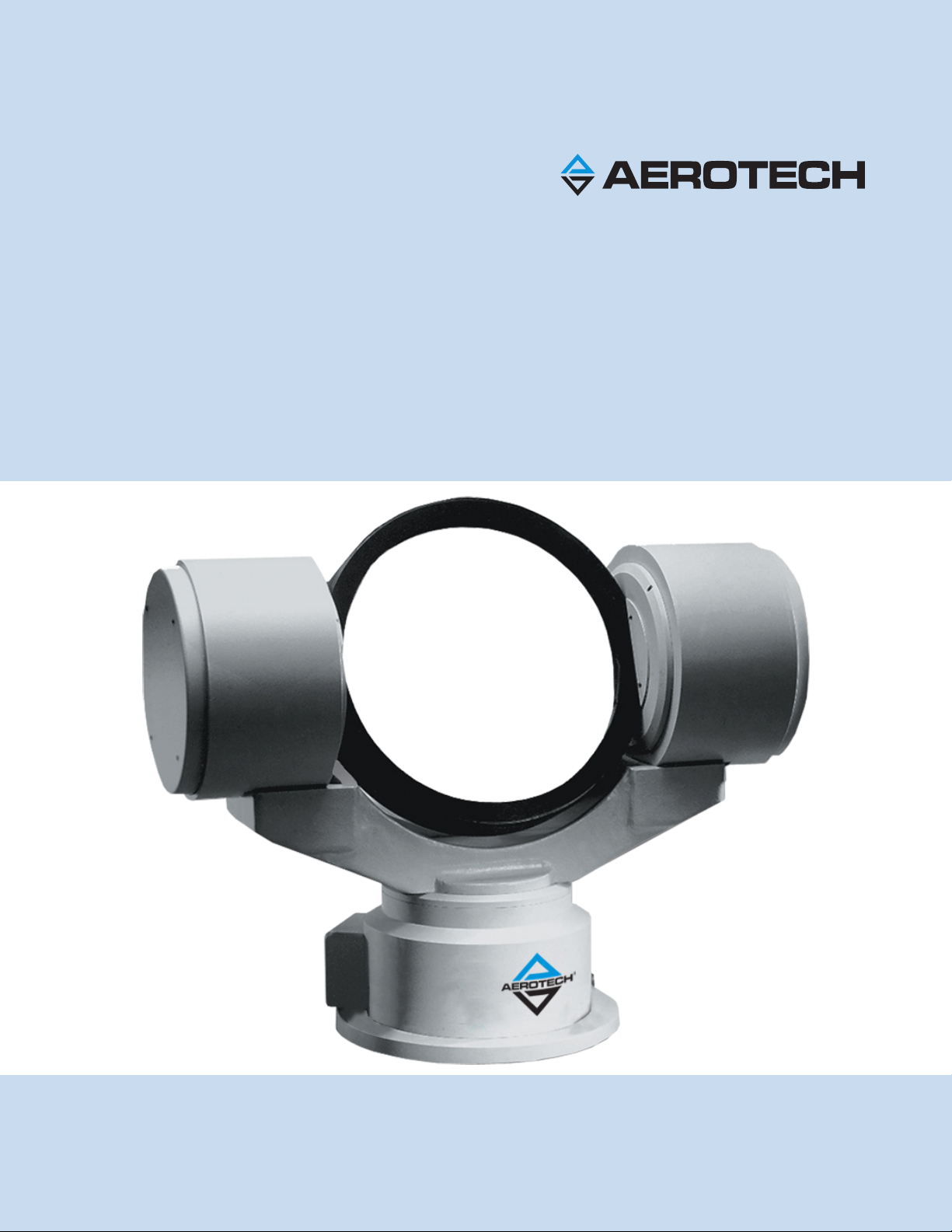
Table of Contents AOM360D User Manual
Safety Procedures and Warnings
This manual tells you how to carefully and correctly use and operate the AOM360D. Read all parts of this
manual before you install or operate the AOM360D or before you do maintenance to your system. To prevent
injury to you and damage to the equipment, obey the precautions in this manual. The precautions that follow
apply when you see a Danger or Warning symbol in this manual. If you do not obey these precautions, injury
to you or damage to the equipment can occur. If you do not understand the information in this manual,
contact Aerotech Global Technical Support.
This product has been designed for light industrial manufacturing or laboratory environments. The protection
provided by the equipment could be impaired if the product is used in a manner not specified by the
manufacturer.
N O T E : Aerotech continually improves its product offerings; listed options may be superseded at any
time. All drawings and illustrations are for reference only and were complete and accurate as of this
manual’s release. Refer to www.aerotech.com for the most up-to-date information.
D A N G E R : This product contains potentially lethal voltages. To reduce the possibility of
electrical shock, bodily injury, or death the following precautions must be followed.
1. Access to the AOM360D and component parts must be restricted while connected to a
power source.
2. Do not connect or disconnect any electrical components or connecting cables while
connected to a power source.
3. Disconnect electrical power before servicing equipment.
4. All components must be properly grounded in accordance with local electrical safety
requirements.
5. Operator safeguarding requirements must be addressed during final integration of the
product.
W A R N I N G : To minimize the possibility of electrical shock, bodily injury or death the
following precautions must be followed.
1. Moving parts can cause crushing or shearing injuries. Access to all stage and motor parts
must be restricted while connected to a power source.
2. Cables can pose a tripping hazard. Securely mount and position all system cables to avoid
potential hazards.
3. Do not expose this product to environments or conditions outside of the listed
specifications. Exceeding environmental or operating specifications can cause damage to
the equipment.
4. The AOM360D must be mounted securely. Improper mounting can result in injury and
damage to the equipment.
5. Use care when moving the AOM360D. Lifting or transporting the AOM360D improperly can
result in injury or damage to the AOM360D.
6. If the product is used in a manner not specified by the manufacturer, the protection
provided by the product can be impaired and result in damage, shock, injury, or death.
7. The motor case temperature may exceed 75°C.
8. Operators must be trained before operating this equipment.
9. All service and maintenance must be performed by qualified personnel.
6 www.aerotech.com