Aerotech ABL1500Z User manual

Revision: 1.03.00
ABL1500Z Hardware Manual
Global Technical Support
Go to www.aerotech.com/global-technical-support for information and support about your Aerotech products. The website
provides downloadable resources (such as up-to-date software, product manuals, and Help files), training schedules, and
PC-to-PC remote technical support. You can also complete Product Return (RMA) forms and get information about repairs
and spare or replacement parts. For immediate help, contact a service office or your sales representative. Have your
customer order number available before you call or include it in your email.
United States (World Headquarters)
Phone: +1-412-967-6440
Fax: +1-412-967-6870
Email: service@aerotech.com
101 Zeta Drive
Pittsburgh, PA 15238-2811
www.aerotech.com
United Kingdom Japan
Phone: +44 (0)1256 855055
Fax: +44 (0)1256 855649
Email: service@aerotech.co.uk
Phone: +81 (0)50 5830 6814
Fax: +81 (0)43 306 3773
Email: service@aerotechkk.co.jp
Germany China
Phone: +49 (0)911 967 9370
Fax: +49 (0)911 967 93720
Email: service@aerotechgmbh.de
Phone: +86 (21) 5508 6731
Email: service@aerotech.com
France Taiwan
Phone: +33 2 37 21 87 65
Email: service@aerotech.co.uk
Phone: +886 (0)2 8751 6690
Email: service@aerotech.tw
This manual contains proprietary information and may not be reproduced, disclosed, or used in whole or in part without the
express written permission of Aerotech, Inc. Product names mentioned herein are used for identification purposes only and
may be trademarks of their respective companies.
Copyright © 2008-2018, Aerotech, Inc., All rights reserved.

ABL1500Z Hardware Manual Table of Contents
Table of Contents
ABL1500Z Hardware Manual 1
Table of Contents 3
List of Figures 4
List of Tables 5
Safety Procedures and Warnings 7
EU Declaration of Incorporation 9
Chapter 1: Overview 11
1.1. Environmental Specifications 12
1.2. Accuracy and Temperature Effects 12
1.3. Basic Specifications 13
1.4. Air Requirements 14
Chapter 2: Installation 17
2.1. Unpacking and Handling the Stage 17
2.2. Dimensions 19
2.3. Securing the Stage to the Mounting Surface 20
2.4. Attaching the Payload to the Stage 22
Load Capability 22
2.5. Setting Up the Pneumatic Counterbalance 24
Chapter 3: Electrical Specifications and Installation 29
3.1. Motor and Feedback Connectors 30
3.2. Motor and Feedback Wiring 33
3.3. Motor and Feedback Specifications 34
3.4. Limits, Marker, and Machine Direction 36
3.5. Motor and Feedback Phasing 37
Chapter 4: Maintenance 39
4.1. Service and Inspection Schedule 39
4.2. Cleaning and Lubrication 39
4.2.1. Cleaning Process 40
4.3. Troubleshooting 42
Appendix A: Warranty and Field Service 43
Appendix B: Revision History 45
Index 47
www.aerotech.com 3

Table of Contents ABL1500Z Hardware Manual
List of Figures
Figure 1-1: Air Fitting Locations for Air Bearing 15
Figure 1-2: Counterbalance Air Flow vs. Counterbalance Pressure 15
Figure 2-1: Lifting Features and Shipping Clamps 18
Figure 2-2: ABL1500Z Dimensions 19
Figure 2-3: Surface Mounting Screws 21
Figure 2-4: Cantilevered Load Capability (Pitch) for Various Peak Accelerations 22
Figure 2-5: Offset Load Capability (Yaw) for Various Peak Applications 23
Figure 2-6: Cantilever and Offset Loading Diagram 23
Figure 2-7: Counterbalance Pressure vs. External Payload 24
Figure 2-8: Connections for Air Bearing and Counterbalance 25
Figure 2-9: Shipping Bracket 26
Figure 3-1: Connector Locations 29
Figure 3-2: Motor and Feedback Wiring 33
Figure 3-3: Machine Direction 36
Figure 3-4: Hall Phasing 37
Figure 3-5: Analog Encoder Phasing Reference Diagram 38
Figure 3-6: Encoder Phasing Reference Diagram (Standard) 38
Figure 4-1: Air Bearing Surfaces and Encoder Scales Require Periodic Cleaning 41
4 www.aerotech.com

ABL1500Z Hardware Manual Table of Contents
List of Tables
Table 1-1: Model Numbers and Ordering Options 11
Table 1-2: Environmental Specifications 12
Table 1-3: ABL1500Z Series Specifications 13
Table 1-4: Air Specifications 14
Table 3-1: Motor Connector Pinouts 31
Table 3-2: Feedback Connector Pinouts 32
Table 3-3: Feedback Specifications 34
Table 3-4: Encoder Specifications 35
Table 3-5: BLMC-192 Motor Specifications 35
Table 4-1: Recommended Cleaning Solvents 39
www.aerotech.com 5

Table of Contents ABL1500Z Hardware Manual
6 www.aerotech.com
This page intentionally left blank.

ABL1500Z Hardware Manual Safety
Safety Procedures and Warnings
Read this manual in its entirety before installing, operating, or servicing this product. If you do not understand
the information contained herein, contact an Aerotech representative before proceeding. Strictly adhere to
the statements given in this section and other handling, use, and operational information given throughout
the manual to avoid injury to you and damage to the equipment.
The following statements apply wherever the Warning or Danger symbol appears within this manual. Failure
to observe these precautions could result in serious injury to those individuals performing the procedures
and/or damage to the equipment.
D A N G E R : This product contains potentially lethal voltages. To reduce the possibility of
electrical shock, bodily injury, or death the following precautions must be followed.
1. Access to the ABL1500Z and component parts must be restricted while connected to a
power source.
2. Do not connect or disconnect any electrical components or connecting cables while
connected to a power source.
3. Disconnect electrical power before servicing equipment.
4. All components must be properly grounded in accordance with local electrical safety
requirements.
5. Operator safeguarding requirements must be addressed during final integration of the
product.
6. PINCHPOINT! Keep Hands Clear while the stage is in motion.
W A R N I N G : To minimize the possibility of electrical shock, bodily injury or death the
following precautions must be followed.
1. Moving parts can cause crushing or shearing injuries. Access to all stage and motor parts
must be restricted while connected to a power source.
2. Cables can pose a tripping hazard. Securely mount and position all system cables to avoid
potential hazards.
3. Do not expose this product to environments or conditions outside of the listed
specifications. Exceeding environmental or operating specifications can cause damage to
the equipment.
4. The ABL1500Z stage must be mounted securely. Improper mounting can result in injury
and damage to the equipment.
5. Use care when moving the ABL1500Z stage. Lifting or transporting the ABL1500Z stage
improperly can result in injury or damage to the ABL1500Z.
6. This product is intended for light industrial manufacturing or laboratory use. Use of this
product for unintended applications can result in injury and damage to the equipment.
7. If the product is used in a manner not specified by the manufacturer, the protection
provided by the product can be impaired and result in damage, shock, injury, or death.
8. The stage forcer temperature may exceed 75°C.
9. Operators must be trained before operating this equipment.
10. All service and maintenance must be performed by qualified personnel.
11. Eye protection must be worn when in the proximity of compressed air components.
www.aerotech.com 7

Safety ABL1500Z Hardware Manual
8 www.aerotech.com
This page intentionally left blank.

ABL1500Z Hardware Manual Declaration of Conformity
EU Declaration of Incorporation
Manufacturer:
Aerotech, Inc.
101 Zeta Drive
Pittsburgh, PA 15238-2811
USA
herewith declares that the product:
ABL1500Z Stage
is intended to be incorporated into machinery to constitute machinery covered by the Directive
2006/42/EC as amended; and that the following harmonized European standards have been
applied:
EN ISO 12100:2010 Safety of machinery - Basic concepts, general principles for
design
EN 60204-1:2010 Safety of machinery - Electrical equipment of machines - Part
1:General requirements
and further more declares that
it is not allowed to put the equipment into service until the machinery into which it is to be
incorporated or of which it is to be a component has been found and declared to be in con-
formity with the provisions of the Directive 2006/42/EC and with national implementing
legislation, i.e., as a whole, including the equipment referred to in this Declaration.
This is to certify that the aforementioned product is in accordance with the applicable requirements of the fol-
lowing Directive(s):
2011/65/EU RoHS2 Directive
Authorized Representative:
Simon Smith, European Director
Address:
Aerotech Ltd
The Old Brick Kiln, Ramsdell, Tadley
Hampshire RG26 5PR
UK
Name
/ Alex Weibel
Position
Engineer Verifying Compliance
Location
Pittsburgh, PA
Date
12/21/2018
www.aerotech.com 9

Declaration of Conformity ABL1500Z Hardware Manual
10 www.aerotech.com
This page intentionally left blank.

ABL1500Z Hardware Manual Overview
Chapter 1: Overview
N O T E : Aerotech continually improves its product offerings; listed options may be superseded at any
time. All drawings and illustrations are for reference only and were complete and accurate as of this
manual’s release. Refer to www.aerotech.com for the most up-to-date information.
Table 1-1: Model Numbers and Ordering Options
ABL1500Z Series Linear Air-Bearing Stage
-050 50 mm travel
-100 100 mm travel
-150 150 mm travel
-200 200 mm travel
Feedback (Required)
-E1 Incremental linear encoder, 1 Vpp amplified sine output
-E2 Incremental linear encoder, 0.1 µm TTL line driver output
-E3 High-accuracy incremental linear encoder, 1 Vpp amplified sine output
Cable Management (Required)
-CMS1 Single axis cable management system
-CMS2 Cable management system for ZT assembly
Metrology (Required)
-PL1 Metrology, uncalibrated with performance plots
-PL2 Metrology, calibrated (HALAR) with performance plots
Accessories (to be ordered as separate line item)
ALIGN-NPA Non-precision XY assembly
ALIGN-PA10 XY assembly; 10 arc sec orthogonality. Alignment to within 7 microns orthogonality for
short travel stages.
ALIGN-PA5 XY assembly; 5 arc sec orthogonality. Alignment to within 3 microns orthogonality for
short travel stages.
ABF Air-bearing filtration kit
www.aerotech.com Chapter 1 11

Overview ABL1500Z Hardware Manual
1.1. Environmental Specifications
W A R N I N G : Do not expose this product to environments or conditions outside of the listed
specifications. Exceeding environmental or operating specifications can cause damage to the
equipment.
Table 1-2: Environmental Specifications
Ambient
Temperature
Operating: 16° to 25° C (61° to 77° F)
The optimal operating temperature is 20° C ±2° C (68° F ±4° F). If at any time the
operating temperature deviates from 20° C degradation in performance could occur.
Storage: 0° to 40° C (32° to 104° F) in original shipping packaging
Humidity
Operating: 20% to 60% RH
Storage: 10% to 70% RH, non-condensing in original packaging. The stage should be
packaged with desiccant if it is to be stored for an extended time.
Altitude
Operating: 0 m to 2,000 m (0 ft to 6,562 ft) above sea level
Contact Aerotech if your specific application involves use above 2,000 m or below sea
level.
Vibration
Use the system in a low vibration environment. Excessive floor or acoustical vibration
can affect system performance. Contact Aerotech for information regarding your
specific application.
Protection
Rating
ABL1500Z stages are not suited for dusty or wet environments. This equates to an
ingress protection rating of IP00.
Use Indoor use only
1.2. Accuracy and Temperature Effects
Due to the small clearances in the air bearing design, extreme temperature environments could cause a
decrease in performance or permanent damage to the stage. Standard Aerotech air-bearing stages are
designed for and built in a 20°C (68°F) environment. The environmental temperature must be controlled to
within 0.25°C per 24 hours to ensure that the ABL1500Z specifications are repeatable over an extended
period of time. The severity of temperature effects on all specifications depends on many different
environmental conditions, including how the ABL1500Z is mounted. Contact the factory for more details.
The -E1 and -E2 encoder scale in the ABL1500Z stage has a coefficient of thermal expansion (CTE) of
3.25 x 10⁻⁶ / °C. The -E3 encoder scale has a CTE of 7.5 x 10⁻⁶ / C. As the stage deviates from 20°C, travel
of the stage as seen by the encoder will change per the appropriate thermal expansion rate.
12 Chapter 1 www.aerotech.com

ABL1500Z Hardware Manual Overview
1.3. Basic Specifications
Table 1-3: ABL1500Z Series Specifications
Basic Model ABL15005Z-
050
ABL15010Z-
100
ABL15015Z-
150
ABL15020Z-
200
Travel 50 mm 100 mm 150 mm 200 mm
Accuracy (1)
-E1 Calibrated ±0.3 µm ±0.3 µm ±0.4 µm ±0.5 µm
Standard ±2.0 µm ±3.0 µm ±5.0 µm ±8.0 µm
-E3 Calibrated ±0.2 µm ±0.2 µm ±0.3 µm ±0.5 µm
Standard ±1.5 µm ±2.5 µm ±4.0 µm ±6.0 µm
Repeatability (Bi-
Directional) (1)
-E1 ±0.1 µm ±0.1 µm ±0.15 µm ±0.2 µm
-E3 ±0.1 µm ±0.1 µm ±0.15 µm ±0.2 µm
Straightness (1) ±0.4 µm ±0.6 µm ±0.8 µm ±1.0 µm
Flatness (1) ±0.4 µm ±0.6 µm ±0.8 µm ±1.0 µm
Pitch ±1 arc sec ±1.5 arc sec ±2 arc sec ±2.5 arc sec
Roll ±1 arc sec ±1.5 arc sec ±2 arc sec ±2.5 arc sec
Yaw ±1 arc sec ±1.5 arc sec ±2 arc sec ±2.5 arc sec
Maximum Speed 300 mm/s
Maximum Acceleration 2 g (no load)
Maximum Force (Continuous) 93.6 N
Load Capacity(2) 15.0 kg
Operating Pressure(3) 80 psi ±5 psig
Air Consumption(4) Stage: 24 - 30 SLPM @ 551 kPa;
Counterbalance: 60 SLPM max
Moving Mass (no load) 5.9 kg
Stage Mass 23.8 kg 26.6 kg 28.5 kg 30.5 kg
Material Aluminum
Mean Time Between Failure 20,000 Hours
(1) Certified with each stage.
(2) Axis orientation for on-axis loading is listed (refer to Section 2.4. for offset loading behavior).
(3) To protect air bearing against under-pressure, an in-line pressure switch tied to the motion controller/amplifier E-Stop is
recommended.
(4) Air supply must be clean, dry to 0° F dew point and filtered to 0.25 μm or better. Recommend nitrogen at 99.9% purity.
NOTES:
lSpecifications are for single-axis systems measured 25 mm above the tabletop; performance of multi-axis system is payload
and workpoint dependent. Consult the Aerotech factory for multi-axis or non-standard applications.
www.aerotech.com Chapter 1 13
Overview ABL1500Z Hardware Manual
1.4. Air Requirements
The quality of the air that you supply to the stage is important to the operation of the stage. Aerotech
recommends that you connect the air supply to the air inlet with a polyurethane air hose.
Table 1-4: Air Specifications
Description
Air Quality
Nitrogen(1) l99.99% pure
lfiltered(2) to 0.25 microns
Compressed Air
lfiltered(2) to 0.25 microns
ldry to 0º F dew point
loil free
Operating Air Pressure 80 psi ± 5 psi (517 to 551 kPa)
Air Consumption Stage 24 - 30 SLPM
Counterbalance 60 SLPM maximum
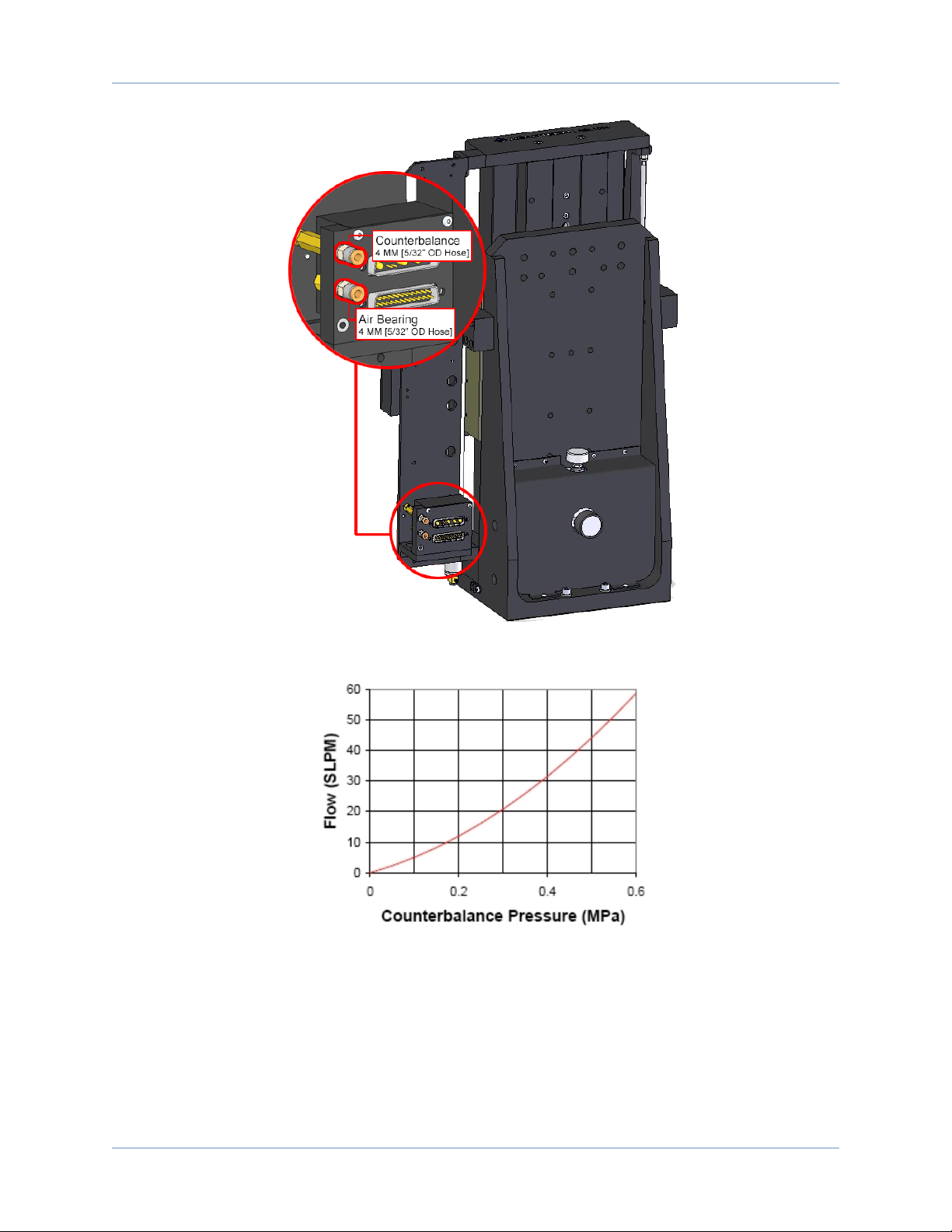
Air Inlet Fitting(3) 4 mm or 5/32" OD Hose
(1) Recommended
(2) The filtration requirement is to prevent particles from clogging the air bearing openings.
(3) Aerotech recommends using a polyurethane air hose.
Aerotech also recommends that you install a pressure switch (P/N: MCA03094) tied to the motion
controller's emergency stop (ESTOP)that will remove power to the air bearing if pressure drops below 40 psi
(a drop in pressure could result in contact between bearing surfaces which could cause damage to the
surfaces). For easier air-supply setup, you can purchase pneumatic kits and filter/filter-dryer kits from
Aerotech. Aerotech’s ABF Air Filtration Unit incorporates air filtration plus a pressure monitoring switch.
The pneumatic counterbalance pressure supply is determined by the amount of payload carried by the stage
(Figure 1-1 and Figure 1-2; for setup, refer to Section 2.5.).
14 Chapter 1 www.aerotech.com
ABL1500Z Hardware Manual Overview
Figure 1-1: Air Fitting Locations for Air Bearing
Figure 1-2: Counterbalance Air Flow vs. Counterbalance Pressure
www.aerotech.com Chapter 1 15

Overview ABL1500Z Hardware Manual
16 Chapter 1 www.aerotech.com
This page intentionally left blank.

ABL1500Z Hardware Manual Mechanical Specifications and Installation
Chapter 2: Installation
W A R N I N G : ABL1500Z installation must be in accordance to instructions provided by this
manual and any accompanying documentation. Failure to follow these instructions could result
in injury or damage to the equipment.
2.1. Unpacking and Handling the Stage
D A N G E R / H E A V Y : Do not attempt to manually lift the ABL1500Z. Refer to for stage mass
specifications.
lLift only with the supplied lifting hardware and lifting straps.
lUse the eyebolts in conjunction with lifting straps.
lThe lifting straps should be configured to pull on the eyebolts in the vertical direction only.
lDo not use the tabletop or cable as lifting points.
W A R N I N G : It is the customer's responsibility to safely and carefully lift the stage.
lMake sure that all moving parts are secure before moving the ABL1500Z. Unsecured
moving parts may shift and cause bodily injury.
lImproper handling could adversely affect the performance of the ABL1500Z. Use care
when moving the ABL1500Z.
N O T E : If any damage has occurred during shipping, report it immediately.
Carefully remove the ABL1500Zfrom its protective shipping container. Use the lifting equipment to gently
set the ABL1500Z on a smooth, flat, and clean surface.
Before operating the ABL1500Z, it is important to let it stabilize at room temperature for at least 12 hours.
Allowing it to stabilize to room temperature will ensure that all of the alignments, preloads, and tolerances are
the same as they were when tested at Aerotech. Use compressed nitrogen or clean, dry, oil-less air to
remove any dust or debris that has collected during shipping.
Lifting Hardware
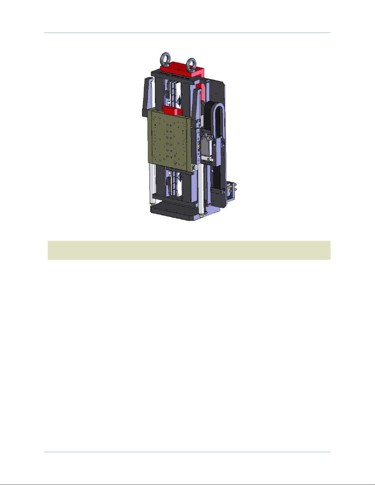
ABL1500Z stages come equipped with lifting bars and eyebolts attached to the stage as shown in Figure 2-1.
For multi-axis assemblies, always lift the system by the lower axis. Lifting by the upper axis may disturb
precision alignments on the system.
Each ABL1500Z has a label listing the system part number and serial number. These numbers contain
information necessary for maintaining or updating system hardware and software. Locate this label and
record the information for later reference.
Shipping Clamps
Red, anodized aluminum shipping brackets have been installed to prevent unwanted motion and potential
damage from occurring during shipment. The brackets must be removed before the ABL1500Z can be
operated. Retain the brackets and hardware for future use.
W A R N I N G : Do not attempt to move the carriage (or table top) of the ABL1500Z until the
shipping brackets have been removed. Moving the carriage with the shipping brackets installed
can cause permanent damage to the ABL1500Z.
www.aerotech.com Chapter 2 17
Mechanical Specifications and Installation ABL1500Z Hardware Manual
Figure 2-1: Lifting Features and Shipping Clamps
N O T E : After removing the lifting features or shipping brackets, retain them for future use. Do not
transport or ship the ABL1500Z without the lifting features or shipping brackets attached.
18 Chapter 2 www.aerotech.com

ABL1500Z Hardware Manual Mechanical Specifications and Installation
2.2. Dimensions
Figure 2-2: ABL1500Z Dimensions
www.aerotech.com Chapter 2 19

Mechanical Specifications and Installation ABL1500Z Hardware Manual
2.3. Securing the Stage to the Mounting Surface
The mounting surface must be flat and have adequate stiffness in order to achieve the maximum
performance from the ABL1500Z stage. When it is mounted to a non-flat surface, the stage can be distorted
as the mounting screws are tightened. This distortion will decrease overall accuracy. Adjustments to the
mounting surface must be done before the stage is secured.
W A R N I N G : Make sure that all moving parts are secure before moving the ABL1500Z.
Unsecured moving parts may shift and cause bodily injury.
D A N G E R : Strong rare-earth magnets are present in the linear motor magnet track. Loose
metal objects (tools, watches, keys, etc.) may cause personal injury and/or damage to the
equipment.
W A R N I N G : The ABL1500Z must be mounted securely. Improper mounting can result in
injury and damage to the equipment.
N O T E : To maintain accuracy, the mounting surface must be flat to within 2.5 µm.
N O T E : The stage base (or Z-Axis angle bracket) is precision machined and verified for flatness prior to
stage assembly at the factory. If machining is required to achieve the desired flatness, it should be
performed on the mounting surface rather than the stage base. Shimming should be avoided if possible. If
shimming is required, it should be minimized to improve the rigidity of the system.
Procedure for ABL1500Z mounting:
W A R N I N G : Do not attempt to move the carriage of the ABL1500Z until the air supply,
detailed in Section 1.4., has been installed. Moving the stage table without air supplied can
cause permanent damage to the stage.
1. Prepare the mounting surface and bottom mounting pads of the angle bracket with precision flatstones
to remove any burrs or high spots.
2. Clean the mounting surface and bottom of the angle bracket with the appropriate cleaners (acetone or
isopropyl alcohol for the angle bracket).
3. Place the stage on the mounting surface
4. Tighten the four mounting screws (Figure Figure 2-3). The typical torque value for M6 socket head cap
screws is 7 N-m.
5. Remove the lifting bracket from the back of the stage assembly (if shipped as a single axis). The lifting
bracket is mounted to the stage with M8-1.25x20mm socket head cap screws.
20 Chapter 2 www.aerotech.com
Table of contents
Other Aerotech Lifting System manuals


