spanesi MINIBENCH Service manual

Leggere attentamente le istruzioni contenute nel presente libretto prima di iniziare ad operare con il MINIBENCH.
Carefully read the instructions in this manual before using MINIBENCH.
Lire attentivement les instructions contenues dans ce manuel avant de commencer à travailler avec le MINIBENCH.
Vor Beginn der Arbeiten mit der MINIBENCH die im vorliegenden Handbuch enthaltenen Anweisungen sorgfältig lesen.
Leer con atención las instrucciones del presente manual antes de iniciar a utilizar el MINIBENCH
MANUALE ISTRUZIONI D'USO E MANUTENZIONE MINIBENCH
OPERATING AND SERVICE MANUAL MINIBENCH
MANUEL D'UTILISATION ET DE MAINTENANCE MINIBENCH
BEDIENUNGS - UNDWARTUNGSHANDBUCH MINIBENCH
MANUAL DE INSTRUCCIONES DE USOY MANUTENCIÓN MINIBENCH
S.p.A.
REV.A04
LIBR0002
LA SOTTOSCRITTA DITTA
THE FIRM
LA SOCIETE
DIE FIRMA
LA ABAJO FIRMANTE
SI RISERVA LA PROPRIETA' DEL SEGUENTE LIBRETTO,VIETA
A CHIUNQUE DI RIPRODURLO O DI COMUNICARLO A TERZI SENZA
L'AUTORIZZAZIONE DELLA PROPRIETARIA E SI RISERVA
LA FACOLTA' DI TUTELARE I PROPRI DIRITTI PERSEGUENDO
I TRASGRESSORI A TERMINI DI LEGGE.
RESERVES OWNERSHIP OF THIS MANUAL, FORBIDS REPRODUCTION OR
COMMUNICATION THEREOF TO THIRD PARTIES WITHOUT THE AUTHORISATION
OF THE OWNER AND RESERVES THE POWER TO SAFEGUARD ITS RIGHTS BY PROSECUTING
ALL TRANSGRESSORS IN ACCORDANCE WITH THE LAW.
SE RESERVE LA PROPRIETE DE CE MANUEL. ELLE INTERDIT
A QUICONQUE DE LE REPRODUIRE OU DE LE COMMUNIQUER A TIERS SANS
L'AUTORISATION DU PROPRIETAIRE ET SE RESERVE LA FACULTE DE DEFENDRE SES DROITS EN POURSUIVANT
LES TRANSGRESSEURS AUX TERMES DE LA LOI.
BEHÄLT SICH DIE RECHTE AN DIESEM HANDBUCH VOR UND ERKLÄRT FÜR UNZULÄSSIG DIE VERVIELFÄTIGUNG
ODER VERBREITUNG AN DRITTE OHNE AUSDRÜCKLICHE GENEHMIGUNG. DES WEITEREN SCHÜTZT SIE IHRE RECHTE UND KANN
VERSTÖßE GESETZESMÄßIG AHNDEN.
SE RESERVA LA PROPIEDAD DEL PRESENTE MANUAL, PROHIBE A QUIENQUIERA REPRODUCIRLO O COMUNICARLO A TERCEROS
SIN LA AUTORIZACIÓN DE LA PROPIETARIA Y SE RESERVA LA FACULTAD DE TUTELAR SUS DERECHOS,
DEMANDANDO A LOS TRANSGRESORES DE ACUERDO CON LA LEY.
iMinibench
2
Il presente manuale è parte integrante del sollevatore
This manual forms an integral part of the
Ce manuel fait partie intégrante de l'élévateur
Das vorliegende Handbuch ist integrierender Teil des Hebers
El presente manual es parte integrante del levantador
MINIBENCH
e va custodito in modo adeguato per permetterne l' integrità
lift and must be kept carefully for consultation whenever required.
et doit être conservé avec soin pour pouvoir le consulter en cas de besoin.
und muss sorgfältig aufbewahrt werden, damit die Unversehrheit sowie
das Nachschlagen während der gesamten Lebensdauer des Gerätes möglich sind.
y se debe guardar en modo adecuado para garantizar su integridad y la consulta durante todo el período de vida de la máquina.
Ulteriori copie del presente libretto istruzioni sono disponibili previa richiesta a:
Further copies are available upon request from:
D'autres copies de ce manuel sont disponibles sur demande à:
Weitere Kopien können auf Anfrage bestellt werden bei:
Ulteriores reproducciones de este manual de instrucciones están disponibles previa solicitud en:
via Praarie, 56/II
35010 SAN GIORGIO DELLE PERTICHE (PADOVA) - ITALIA
S.p.A.
S.p.A.
Minibenchi
3
MODELLO
NUMERO DI SERIE
ANNO COSTRUZIONE
PORTATA MAX KG
PRESSIONE OLIO BAR
MASSA (PESO) kg
DATA DI CONSEGNA
CLIENTE
ORDINE N.
TRASCRIVERE I DATI RIPORTATI NELLATARGHETTA DI IDENTIFICAZIONE DEL SOLLEVATORE
DATI RELATIVIALLA CONSEGNA DEL SOLLEVATORE
I
OFFICINEAUTORIZZATE DALLA SPANESI S.p.A. A CUI RIVOLGERSI PER EVENTUALI INTERVENTI
DIASSISTENZA SUL SOLLEVATORE

MODEL
SERIAL NUMBER
YEAR OF MANUFACTURE
MAX CAPACITY IN KG
OIL PRESSURE IN BAR
WEIGHT IN KG
DELIVERY DATE
CUSTOMER
ORDER NO.
RECORD BELOWTHE INFORMATION GIVEN INTHE LIFT IDENTIFICATION PLATE
INFORMATION CONCERNING DELIVERY OFTHE LIFT
GB
WORKSHOPSAUTHORISED BY SPANESI S.p.A. FORTECHNICAL SUPPORT
iMinibench
4

Minibenchi
5
MODELE
N° DE SERIE
CHARGE MAX. EN KG
POIDS EN KG
DATE DE LIVRAISON
CLIENT
COMMANDE N°
TRANSCRIRE LES DONNEES REPORTEES SUR LA PLAQUE D'IDENTIFICATION DE L'ELEVATEUR
DONNEES RELATIVESA LA LIVRAISON DE L'ELEVATEUR
F
ATELIERSAGREES PAR SPANESI S.p.A.OU S'ADRESSER POUR DES REPARATIONS EVENTUELLES
SUR L'ELEVATEUR
PRESSION DE L'HUILE EN BARS
ANNEE DE CONSTRUCTION

iMinibench
6
MODELL
SERIENNUMMER
BAUJAHR
MAXTRAGKRAFT kg
ÖLDRUCK bar
MASSE (GEWICHT) kg
LIEFERDATUM
KUNDE
AUFTRAGSNR.
DIE DATENAUF DEM GERÄTESCHILD DES HEBERS HIER ÜBERTRAGEN
LIEFERDATEN FÜR DEN HEBER
D
VERTRAGSWERKSTATTVON SPANESI S.p.A.,AN DIE SICH FÜR EVENTUELLE
KUNDENDIENST-MAßNAHMENAM HEBER ZUWENDEN IST

Minibenchi
7
MODELO
NÚMERO DE SERIE
AÑO DE CONSTRUCCIÓN
CAPACIDAD MÁX KG
PRESIÓN DE ACEITE BAR
MASA (PESO) Kg
FECHA DE ENTREGA
CLIENTE
ORDEN N
TRANSCRIBIR LOS DATOS INDICADOS EN LA ETIQUETA DE IDENTIFICACIÓN DEL LEVANTADOR
DATOS RELATIVOSA LA ENTREGA DEL LEVANTADOR
E
TALLERESAUTORIZADOS POR SPANESI S.p.A. A LOS QUE DIRIGIRSE PARA
EVENTUALES INTERVENCIONES DEASISTENCIA PARA EL LEVANTADOR
SEZIONE 1 DESCRIZIONE E CARATTERISTICHE
PRINCIPALI . . . . . . . . . . . . . . . . . 12
1INTRODUZIONE. . . . . . . . . . . . . . . . . 12
1.1 GARANZIA. . . . . . . . . . . . . . . . . . . . . . 14
1.1.1 ESCLUSIONI DALLA GARANZIA . . . 14
1.2 LA CERTIFICAZIONE CE. . . . . . . . . . . 16
1.3 DESTINAZIONE D'USO . . . . . . . . . . . 16
1.4 DESCRIZIONE DEL SOLLEVATORE. . 16
1.5 DESCRIZIONE SISTEMI DITIRO. . . . . 22
1.6 IDENTIFICAZIONE. . . . . . . . . . . . . . . . 26
1.7 LIVELLO SONORO . . . . . . . . . . . . . . . 26
1.8 CARATTERISTICHETECNICHE . . . . . 30
SEZIONE 2 NORME DI SICUREZZA E PREVENZIONE
INFORTUNI . . . . . . . . . . . . . . . . . 32
2LIVELLI DI PERICOLO . . . . . . . . . . . . . 32
2.1 SEGNALI DI SICUREZZA . . . . . . . . . . 34
2.2 TABELLA PORTATE . . . . . . . . . . . . . . . 34
2.3 ABBIGLIAMENTO. . . . . . . . . . . . . . . . . 38
2.4 ECOLOGIA ED INQUINAMENTO. . . 38
2.5 USO IN SICUREZZA . . . . . . . . . . . . . . 38
2.6 MANUTENZIONE IN SICUREZZA . . 42
SEZIONE 3 TRASPORTO, SCARICO E MESSA IN
SERVIZIO . . . . . . . . . . . . . . . . . . 44
3TRASPORTO E SCARICO. . . . . . . . . . 44
3.1 INSTALLAZIONE . . . . . . . . . . . . . . . . . 44
3.1.1 SCELTA DELLA POSIZIONE . . . . . . . . 44
3.1.2 PRIMA DELLA POSA IN OPERA . . . . 48
3.2 POSA IN OPERA SOLLEVATORE. . . . 48
3.2.1 COLLEGAMENTO IMPIANTO
PNEUMATICO . . . . . . . . . . . . . . . . . . . 52
3.2.2 COLLEGAMENTO IMPIANTO
ELETTRICO. . . . . . . . . . . . . . . . . . . . . . 52
3.3 POSA IN OPERA
DEL BRACCIO DITIRO . . . . . . . . . . . . . 58
SEZIONE 4 ISTRUZIONI D'USO . . . . . . . . . . . . 60
4PRIMA DELL'USO. . . . . . . . . . . . . . . . . 60
4.1 VERIFICA FUNZIONAMENTO
DISPOSITIVI DI EMERGENZA. . . . . . . 60
4.1.1 PULSANTE D' EMERGENZA . . . . . . . 60
4.1.2 PULSANTE DI RIPRISTINO . . . . . . . . . 60
4.2 COMANDI DEL SOLLEVATORE . . . . 60
4.3 USO DEL SOLLEVATORE . . . . . . . . . . 64
4.3.1 SALITA E DISCESA DEL MINIBENCH 64
4.3.2 USO DEL MINIBENCH COME
SOLLEVATORE SENZA IL PUNTONE
DITIRO . . . . . . . . . . . . . . . . . . . . . . . . . 66
4.3.3 USO DEL MINIBENCH CON
PUNTONE DITIRO . . . . . . . . . . . . . . . 68
4.3.4 APPLICAZIONE DEL PUNTONE DI
TIRO AL MINIBENCH . . . . . . . . . . . . . 72
4.3.5 USO DEL PUNTONE DITIRO
ORIENTABILE . . . . . . . . . . . . . . . . . . . . 72
4.3.6 DISINSERIMENTO DEL PUNTONE DI
TIRO DAL MINIBENCH. . . . . . . . . . . . 76
SEZIONE 5 DISPOSITIVI DI SICUREZZA . . . . . . . 78
5DISPOSITIVI DI SICUREZZA. . . . . . . . 78
5.1 SICUREZZA MECCANICA
ANTIRITORNO . . . . . . . . . . . . . . . . . . . . . . . 78
5.2 VALVOLA
DI BLOCCO DI SICUREZZA . . . . . . . 78
5.3 PULSANTE ARRESTO
DI EMERGENZA. . . . . . . . . . . . . . . . . . 78
5.4 PULSANTE DI RIPRISTINO . . . . . . . . . 78
SECTION 1 DESCRIPTION AND MAIN FEATURES . 12
1INTRODUCTION. . . . . . . . . . . . . . . . . 12
1.1 GUARANTEE . . . . . . . . . . . . . . . . . . . . 14
1.1.1 ITEMS EXCLUDED FROMTHE
GUARANTEE . . . . . . . . . . . . . . . . . . . . 14
1.2 EC CERTIFICATION. . . . . . . . . . . . . . . 16
1.3 INTENDED USE . . . . . . . . . . . . . . . . . . 16
1.4 DESCRIPTION OFTHE MINIBENCH. 16
1.5 DESCRIPTION
OFTHE PULL SYSTEMS. . . . . . . . . . . . 22
1.6 IDENTIFICATION. . . . . . . . . . . . . . . . . 26
1.7 NOISE LEVEL . . . . . . . . . . . . . . . . . . . . 26
1.8 TECHNICAL FEATURES . . . . . . . . . . . 30
SECTION 2 SAFETY AND ACCIDENT PREVENTION
REGULATIONS . . . . . . . . . . . . . . . 32
2HAZARD LEVELS. . . . . . . . . . . . . . . . . 32
2.1 SAFETY SIGNS . . . . . . . . . . . . . . . . . . . 34
2.2 CAPACITYTABLE . . . . . . . . . . . . . . . . . 34
2.3 CLOTHING. . . . . . . . . . . . . . . . . . . . . . 38
2.4 ECOLOGY AND POLLUTION. . . . . . 38
2.5 SAFE USE. . . . . . . . . . . . . . . . . . . . . . . . 38
2.6 SAFE MAINTENANCE. . . . . . . . . . . . . 42
SECTION 3 TRANSPORT, UNLOADING AND
COMMISSIONING . . . . . . . . . . . . . 44
3TRANSPORT AND UNLOADING. . . 44
3.1. INSTALLATION. . . . . . . . . . . . . . . . . . . 44
3.1.1 CHOOSINGTHE POSITION . . . . . . . 44
3.1.2 BEFORE INSTALLATION . . . . . . . . . . . 48
3.2 LIFT INSTALLATION . . . . . . . . . . . . . . 48
3.2.1 CONNECTINGTHE PNEUMATIC
SYSTEM . . . . . . . . . . . . . . . . . . . . . . . . . 52
3.2.2 CONNECTINGTHE ELECTRICAL
SYSTEM . . . . . . . . . . . . . . . . . . . . . . . . . 52
3.3 INSTALLINGTHE PULL ARM . . . . . . . 58
SECTION 4 OPERATING INSTRUCTIONS . . . . . . . 60
4BEFORE USE . . . . . . . . . . . . . . . . . . . . 60
4.1 CHECKING OPERATION OFTHE
EMERGENCY DEVICES . . . . . . . . . . . . 60
4.1.1 EMERGENCY BUTTON. . . . . . . . . . . . 60
4.1.2 RESET BUTTON . . . . . . . . . . . . . . . . . . 60
4.2 LIFT CONTROLS . . . . . . . . . . . . . . . . . 60
4.3 USINGTHE LIFT. . . . . . . . . . . . . . . . . . 64
4.3.1 RAISING AND LOWERINGTHE
MINIBENCH . . . . . . . . . . . . . . . . . . . . . 64
4.3.2 USINGTHE MINIBENCH AS A LIFT
WITHOUTTHE PULL BAR . . . . . . . . . 66
4.3.3 USINGTHE MINIBENCHWITHTHE
PULL BAR . . . . . . . . . . . . . . . . . . . . . . . 68
4.3.4 FITTINGTHE PULL BARTOTHE
MINIBENCH . . . . . . . . . . . . . . . . . . . . . 72
4.3.5 USINGTHE ADJUSTABLE
PULL BAR . . . . . . . . . . . . . . . . . . . . . . . 72
4.3.6 REMOVINGTHE PULL BAR FROM
THE MINIBENCH . . . . . . . . . . . . . . . . . 76
SECTION 5 SAFETY DEVICES . . . . . . . . . . . . . 78
5SAFETY DEVICES . . . . . . . . . . . . . . . . . 78
5.1 NON-RETURN MECHANICAL
SAFETY DEVICE . . . . . . . . . . . . . . . . . . 78
5.2 SAFETY LOCKVALVE. . . . . . . . . . . . . . 78
5.3 EMERGENCY STOP BUTTON . . . . . . 78
5.4 RESET BUTTON . . . . . . . . . . . . . . . . . . 78
5.5 LOWVOLTAGE CONTROLS
ELETRICAL CIRCUIT . . . . . . . . . . . . . . 80
iMinibench
8
INDICE
I
INDICE
I
CONTENTS
GB
INDEX
F
INHALT
D
ÌNDICE
E
CONTENTS
GB
Minibenchi
9
INDICE
FINHALT
DÌNDICE
E
iMinibench
SECTION 1 DESCRIPTION ET PRINCIPALES
CARACTERISTIQUES. . . . . . . . . . . . 13
1INTRODUCTION. . . . . . . . . . . . . . . . . 13
1.1 GARANTIE . . . . . . . . . . . . . . . . . . . . . . 15
1.1.1 EXCLUSIONS DE LA GARANTIE. . . . 15
1.2 LA CERTIFICATION CE. . . . . . . . . . . . 17
1.3 USAGE PREVU . . . . . . . . . . . . . . . . . . . 17
1.4 DESCRIPTION DE L'ELEVATEUR . . . . 17
1.5 DESCRIPTION DES SYSTEMES
DETIRAGE. . . . . . . . . . . . . . . . . . . . . . . . . . . 23
1.6 IDENTIFICATION. . . . . . . . . . . . . . . . . 27
1.7 NIVEAU DE BRUIT. . . . . . . . . . . . . . . . 27
1.8 DONNEESTECHNIQUES . . . . . . . . . . 30
SECTION 2 NORMES DE SECURITE ET DE
PREVENTION DES ACCIDENTS . . . . . 33
2NIVEAUX DE RISQUE. . . . . . . . . . . . . 33
2.1 SIGNAUX DE SECURITE. . . . . . . . . . . 35
2.2 TABLEAU DES CHARGES . . . . . . . . . . 35
2.3 HABILLEMENT . . . . . . . . . . . . . . . . . . . 37
2.4 ECOLOGIE ET POLLUTION. . . . . . . . 37
2.5 EMPLOI ENTOUTE SECURITE . . . . . . 39
2.6 MAINTENANCE
ENTOUTE SECURITE . . . . . . . . . . . . . 43
SECTION 3 TRANSPORT, DECHARGEMENT ET MISE
EN SERVICE . . . . . . . . . . . . . . . . 45
3TRANSPORT ET DECHARGEMENT . 45
3.1 INSTALLATION. . . . . . . . . . . . . . . . . . . 45
3.1.1 ZONE D'INSTALLATION . . . . . . . . . . 45
3.1.2 CONTROLES
AVANT L'INSTALLATION . . . . . . . . . . 49
3.2 INSTALLATION DE L'ELEVATEUR . . . 49
3.2.1 RACCORDEMENT DU CIRCUIT
PNEUMATIQUE . . . . . . . . . . . . . . . . . . 53
3.2.2 BRANCHEMENT DE L'INSTALLATION
ELECTRIQUE. . . . . . . . . . . . . . . . . . . . . 53
3.3 INSTALLATION
DU BRAS DETIRAGE. . . . . . . . . . . . . . 59
SECTION 4 MODE D'EMPLOI . . . . . . . . . . . . . 61
4AVANT L'EMPLOI. . . . . . . . . . . . . . . . . 61
4.1 CONTROLE FONCTIONNEMENT
DES DISPOSITIFS D'URGENCE . . . . . 61
4.1.1 BOUTON D'URGENCE. . . . . . . . . . . . 61
4.1.2 BOUTON DE REMISE A ZERO. . . . . . 61
4.2 COMMANDES DE L'ELEVATEUR. . . . 61
4.3 UTILISATION DE L'ELEVATEUR . . . . . 65
4.3.1 MONTEE ET DESCENTE
DU MINIBENCH . . . . . . . . . . . . . . . . . . . . . 65
4.3.2 UTILISATION DU MINIBENCH COMME
ELEVATEUR SANS ETRESILLON DE
TIRAGE . . . . . . . . . . . . . . . . . . . . . . . . . 67
4.3.3 UTILISATION DU MINIBENCH
AVEC L'ETRESILLON DETIRAGE. . . . 69
4.3.4 MONTAGE DE L'ETRESILLON DE
TIRAGE SUR LE MINIBENCH . . . . . . . 73
4.3.5 UTILISATION DE L'ETRESILLON DE
TIRAGE ORIENTABLE . . . . . . . . . . . . . 73
4.3.6 DEMONTAGE DE L'ETRESILLON
DETIRAGE ORIENTABLE. . . . . . . . . . . 77
SEZIONE 5 DISPOSITIFS DE SECURITE . . . . . . . 79
5DISPOSITIFS DE SECURITE. . . . . . . . . 79
5.1 SECURITE MECANIQUE
ANTI-RETOUR . . . . . . . . . . . . . . . . . . . 79
ABSCHNITT 1
BESCHREIBUNG UND
HAUPTEIGENSCHAFTEN . . . . . . . . . 13
1 EINFÜHRUNG . . . . . . . . . . . . . . . . . . . 13
1.1 GARANTIE . . . . . . . . . . . . . . . . . . . . . . 15
1.1.1 GARANTIEAUSNAHMEN. . . . . . . . . . 15
1.2 CE-ZERTIFIZIERUNG . . . . . . . . . . . . . . 17
1.3 GEBRAUCHSBESTIMMUNG . . . . . . . . 17
1.4 BESCHREIBUNG DES HEBERS . . . . . . 17
1.5 BESCHREIBUNG
DER ZUGSYSTEME . . . . . . . . . . . . . . . 23
1.6 KENNZEICHNUNG. . . . . . . . . . . . . . . 27
1.7 GERÄUSCHPEGEL . . . . . . . . . . . . . . . . 27
1.8 TECHNISCHE EIGENSCHAFTEN. . . . 30
ABSCHNITT 2
SICHERHEITSVORSCHRIFTEN UND
UNFALLVERHÜTUNG . . . . . . . . . . . 33
2GEFAHRENSTUFEN. . . . . . . . . . . . . . . 33
2.1 SICHERHEITSHINWEISE . . . . . . . . . . . 35
2.2 TABELLE ZURTRAGKRAFT. . . . . . . . . 35
2.3 KLEIDUNG . . . . . . . . . . . . . . . . . . . . . . 37
2.4 ÖKOLOGIE/ UMWELTBELASTUNG . 37
2.5 SICHERE BENUTZUNG. . . . . . . . . . . . 39
2.6 SICHERHEIT BEI DERWARTUNG . . . 43
ABSCHNITT 3
TRANSPORT, ABLADEN UND
INBETRIEBNAHME . . . . . . . . . . . . 45
3TRANSPORT UND ABLADEN. . . . . . 45
3.1 INSTALLATION. . . . . . . . . . . . . . . . . . . 45
3.1.1 WAHL DES INSTALLATIONSORTES. 45
3.1.2 VOR DER INSTALLATION. . . . . . . . . . 49
3.2 INSTALLATION. . . . . . . . . . . . . . . . . . . 49
3.2.1 ANSCHLUSS DER PNEUMATIK . . . . . 53
3.2.2 ANSCHLUSS DER ELEKTRIK. . . . . . . . 53
3.3 INSTALLIEREN DES ZUGARMS . . . . . 59
ABSCHNITT 4
BEDIENUNGSANLEITUNG . . . . . . . . 61
4VOR GEBRAUCH. . . . . . . . . . . . . . . . . 61
4.1 PRÜFEN DER
FUNKTIONSTÜCHTIGKEIT DER
SICHERHEITSVORRICHTUNGEN. . . . 61
4.1.1 NOT-AUS-SCHALTER . . . . . . . . . . . . . 61
4.1.2 RESET-DRUCKKNOPF . . . . . . . . . . . . . 61
4.2 BEDIENUNGGEN DES HEBERS . . . . . 61
4.3 BENUTZEN DES HEBERS . . . . . . . . . . 65
4.3.1 AUF- UND ABWÄRTSBEWEGEN
DER MINIBENCH . . . . . . . . . . . . . . . . . 65
4.3.2 BENUTZEN DER MINIBENCH ALS
HEBER OHNE ZUGSTREBE . . . . . . . . 67
4.3.3 BENUTZEN DER MINIBENCH
MIT ZUGSTREBE . . . . . . . . . . . . . . . . . 69
4.3.4 ANSCHLUSS DER ZUGSTREBE AN
DER MINIBENCH . . . . . . . . . . . . . . . . . 73
4.3.5 BENUTZEN DER AUSRICHTBAREN
ZUGSTREBE . . . . . . . . . . . . . . . . . . . . . 73
4.3.6 ENTFERNEN DER ZUGSTREBE
VON DER MINIBENCH. . . . . . . . . . . . 77
ABSCHNITT 5
SICHERHEITSVORRICHTUNGEN. . . . . 79
5SICHERHEITSVORRICHTUNGEN. . . . 79
5.1 MECHANISCHE RÜCKSCHLAG-
SICHERHEITSVORRICHTUNG . . . . . . 79
SECCIÓN 1 DESCRIPCIÓN Y CARACTERÍSTICAS
PRINCIPALES . . . . . . . . . . . . . . . . . 13
1 INTRODUCCIÓN . . . . . . . . . . . . . . . . 13
1.1 GARANTÍA . . . . . . . . . . . . . . . . . . . . . . 15
1.1.1 EXCLUSIONES DE LA GARANTÍA . . 15
1.2 LA CERTIFICACIÓN CE. . . . . . . . . . . . 17
1.3 DESTINACIÓN DE USO . . . . . . . . . . . 17
1.4 DESCRIPCIÓN DEL LEVANTADOR. . 17
1.5 DESCRIPCIÓN
DEL SISTEMA DETIRO . . . . . . . . . . . . 23
1.6 IDENTIFICACIÓN. . . . . . . . . . . . . . . . . 27
1.7 NIVEL DE RUIDO. . . . . . . . . . . . . . . . . 27
1.8 CARACTERÍSTICASTÉCNICAS . . . . . 30
SECCIÓN 2 NORMAS DE SEGURIDAD Y PREVENCIÓN
DE ACCIDENTES . . . . . . . . . . . . . . 33
2NIVELES DE PELIGRO . . . . . . . . . . . . . 33
2.1 SEÑALES DE SEGURIDAD . . . . . . . . . 35
2.2 TABLA DE LAS CAPACIDADES . . . . . 35
2.3 VESTUARIO. . . . . . . . . . . . . . . . . . . . . . 37
2.4 ECOLOGÍAY CONTAMINACIÓN. . . 37
2.5 USO EN CONDICIONES
DE SEGURIDAD . . . . . . . . . . . . . . . . . . . . . . 39
2.6 SEGURIDAD
EN LA MANUTENCIÓN. . . . . . . . . . . 43
SECCIÓN 3 TRANSPORTE Y DESCARGA . . . . . . . 45
3TRANSPORTEY DESCARGA . . . . . . . 45
3.1 INSTALACIÓN . . . . . . . . . . . . . . . . . . . 45
3.1.1 SELECCIÓN DE LA POSICIÓN . . . . . 45
3.1.2 ANTES DE LA INSTALACIÓN . . . . . . 49
3.2 INSTALACIÓN DEL LEVANTADOR. . 49
3.2.1 CONEXIÓN
DEL SISTEMA NEUMÁTICO. . . . . . . . . . 53
3.2.2 CONEXIÓN
DEL SISTEMA ELÉCTRICO . . . . . . . . . 53
3.3 INSTALACIÓN
DEL CODAL DETIRO. . . . . . . . . . . . . 59
SECCIÓN 4 INSTRUCCIONES DE OPERACIÓN . . . 61
4ANTES DE LA UTILIZACIÓN. . . . . . . 61
4.1 COMPROBACIÓN DEL
FUNCIONAMIENTO DE LOS
DISPOSITIVOS DE EMERGENCIA . . . 61
4.1.1 INTERRUPTOR DE EMERGENCIA . . . 61
4.1.2 INTERRUPTOR DE REPOSICIÓN. . . . 61
4.2 MANDOS DEL LEVANTADOR. . . . . . 61
4.3 USO DEL LEVANTADOR . . . . . . . . . . 65
4.3.1 SALIDAY BAJADA DEL MINIBENCH. 65
4.3.2 USO DEL MINIBENCH COMO
LEVANTADOR SIN
EL CODAL DETIRO. . . . . . . . . . . . . . . 67
4.3.3 USO DEL MINIBENCH COMO
LEVANTADOR CON
EL CODAL DETIRO. . . . . . . . . . . . . . . . . . 69
4.3.4 APLICACIÓN DEL CODAL
DETIRO AL MINIBENCH . . . . . . . . . . 73
4.3.5 USO DEL CODAL DETIRO
ORIENTABLE. . . . . . . . . . . . . . . . . . . . . 73
4.3.6 EXTRACCIÓN DEL CODAL
DETIRO DEL MINIBENCH . . . . . . . . . 77
SECCIÓN 5 DISPOSITIVOS DE SEGURIDAD . . . . . 79
5DISPOSITIVOS DE SEGURIDAD. . . . . 79
5.1 DISPOSITIVO DE SEGURIDAD
MECÁNICA CON RETENCIÓN. . . . . 79

5.5 CIRCUITO ELETTRICO DEI COMANDI
IN BASSATENSIONE. . . . . . . . . . . . . . 80
5.6 SALVAMOTORE
MAGNETOTERMICO. . . . . . . . . . . . . . 80
5.7 SEGNALI DI AVVISO DI SICUREZZA 80
SEZIONE 6 ACCESSORI . . . . . . . . . . . . . . . . . 80
6.1 DOTAZIONE DI SERIE. . . . . . . . . . . . . 80
6.2 DOTAZIONE BRACCIO DITIRO
ORIENTABILE . . . . . . . . . . . . . . . . . . . . 80
SEZIONE 7 IMPIANTI . . . . . . . . . . . . . . . . . . 82
7IMPIANTI SOLLEVATORE . . . . . . . . . . 82
7.1 SCHEMA OLEODINAMICO
SOLLEVATORE . . . . . . . . . . . . . . . . . . . 82
7.2 SCHEMA PNEUMATICO
SOLLEVATORE . . . . . . . . . . . . . . . . . . . 84
7.3 SCHEMA OLEOPMEUMATICO
BRACCIO DITIRO SOLLEVATORE. . . 88
7.4 SCHEMA ELETTRICO . . . . . . . . . . . . . 90
SEZIONE 8 MANUTENZIONE. . . . . . . . . . . . . . 94
8MANUTENZIONE . . . . . . . . . . . . . . . . 94
8.1 MANUTENZIONE ORDINARIA. . . . . 94
8.2 MANUTENZIONE STRAORDINARIA 96
SEZIONE 9 RICERCA GUASTI
E PROBABILI RIMEDI. . . . . . . . . . . 98
9GUASTI, CAUSE E RIMEDI. . . . . . . . . . 98
SEZIONE 10 PARTI DI RICAMBIO. . . . . . . . . . . 104
10 RICAMBI . . . . . . . . . . . . . . . . . . . . . . . 104
TAVOLA 1 SOLLEVATORE . . . . . . . . . . . . . . 107
TAVOLA 2 BRACCIO DI TIRO ORIENTABILE . . . 110
TAVOLA 3 PULPITO DI COMANDO. . . . . . . . . 113
5.6 MAGNETO-THERMAL OVERLOAD
CUTOUT. . . . . . . . . . . . . . . . . . . . . . . . 80
5.7 SAFETYWARNING SIGNS . . . . . . . . . 80
SECTION 6 ACCESSORIES. . . . . . . . . . . . . . . . 80
6.1 STANDARD ACCESSORIES. . . . . . . . . 80
6.2 ADJUSTABLE PULL ARM
ACCESSORIES. . . . . . . . . . . . . . . . . . . . 80
SECTION 7 SYSTEMS . . . . . . . . . . . . . . . . . . 82
7LIFT SYSTEMS. . . . . . . . . . . . . . . . . . . . 82
7.1 LIFT HYDRAULIC DIAGRAM . . . . . . . 82
7.2 LIFT PNEUMATIC DIAGRAM . . . . . . . 84
7.3 LIFT PULL ARM HYDRAULIC
PNEUMATIC DIAGRAM. . . . . . . . . . . . 88
7.4 WIRING DIAGRAM . . . . . . . . . . . . . . . 90
SECTION 8 MAINTENANCE. . . . . . . . . . . . . . . 94
8. MAINTENANCE. . . . . . . . . . . . . . . . . . 94
8.1 ROUTINE MAINTENANCE. . . . . . . . . 94
8.2 EXTRAORDINARY MAINTENANCE. 96
SECTION 9 TROUBLESHOOTING AND PROBABLE
SOLUTIONS . . . . . . . . . . . . . . . . . 99
9FAULTS, CAUSES
AND SOLUTIONS. . . . . . . . . . . . . . . . 99
SECTION 10 SPARE PARTS . . . . . . . . . . . . . . . . 104
10 SPARE PARTS. . . . . . . . . . . . . . . . . . . 104
EXPLODED
DRAWING 1 LIFT. . . . . . . . . . . . . . . . . . . . . 107
EXPLODED
DRAWING 2 ADJUSTABLE PULL ARM . . . . . . . . 110
EXPLODED
DRAWING 3 CONTROL CONSOLE. . . . . . . . . . . 113
iMinibench
10
INDICE
ICONTENTS
GB

5.2 SOUPAPE DE BLOCAGE
DE SECURITE . . . . . . . . . . . . . . . . . . . . 79
5.3 BOUTON D'ARRET D'URGENCE . . . 79
5.4 BOUTON DE REMISE A ZERO. . . . . . 79
5.5 CIRCUIT ELECTRIQUE DES
COMMANDES EN BASSETENSION . 81
5.6 COUPE-CIRCUIT
MAGNETOTHERMIQUE . . . . . . . . . . . 81
5.7 SIGNAUX DE SECURITE. . . . . . . . . . . 81
SECTION 6 ACCESSOIRES. . . . . . . . . . . . . . . . 81
6.1 ACCESSOIRES STANDARD. . . . . . . . . 81
6.2 ACCESSOIRES DU BRAS
DETIRAGE ORIENTABLE. . . . . . . . . . . 81
SECTION 7 INSTALLATIONS . . . . . . . . . . . . . . 83
7INSTALLATIONS
DE L'ELEVATEUR . . . . . . . . . . . . . . . . . 83
7.1 SCHEMA HYDRAULIQUE
DE L'ELEVATEUR . . . . . . . . . . . . . . . . . . . . . 83
7.2 SCHEMA PNEUMATIQUE DE
L'ELEVATEUR . . . . . . . . . . . . . . . . . . . . 85
7.3 SCHEMA OLEOPNEUMATIQUE DU
BRAS DETIRAGE DE L'ELEVATEUR. . 89
7.4 SCHEMA ELECTRIQUE . . . . . . . . . . . . 91
SECTION 8 MAINTENANCE. . . . . . . . . . . . . . . 95
8MAINTENANCE. . . . . . . . . . . . . . . . . . 95
8.1 MAINTENANCE COURANTE . . . . . . 95
8.2 MAINTENANCE SUPPLEMENTAIRE . 97
SECTION 9 RECHERCHE DES PANNES ET
SOLUTIONS POSSIBLES. . . . . . . . . 100
9PANNES, CAUSES ET SOLUTIONS . 100
SECTION 10 PIECES DETACHEES . . . . . . . . . . . 105
10 PIECES DETACHEES. . . . . . . . . . . . . . 105
TABLE 1 ELEVATEUR . . . . . . . . . . . . . . . . 107
TABLE 2 BRAS DE TIRAGE ORIENTABLE . . . . 110
TABLE 3 PUPITRE DE COMMANDE . . . . . . . 113
5.2 SICHERHEITSSPERRVENTIL. . . . . . . . . 79
5.3 NOT-AUS-SCHALTER . . . . . . . . . . . . . 79
5.4 RESET-DRUCKKNOPF . . . . . . . . . . . . . 79
5.5 NIEDERSPANNUNGS-
BETRIEBSSTROMSTEUERKREIS. . . . . . 81
5.6 MAGNETOTHERMISCHER
ÜBERLASTSCHUTZ. . . . . . . . . . . . . . . 81
5.7 SICHERHEITS-WARNHINWEISE . . . . 81
ABSCHNITT 6
HEBERZUBEHÖR. . . . . . . . . . . . . . 81
6.1 SERIENMÄßIGE AUSSTATTUNG. . . . . 81
6.2 ZUBEHÖR
AUSRICHTBARER ZUGARM. . . . . . . . 81
ABSCHNITT 7
SYSTEME . . . . . . . . . . . . . . . . . . 83
7SYSTEME DES HEBERS . . . . . . . . . . . . 83
7.1 ÖLHYDRAULIKPLAN
DES HEBERS . . . . . . . . . . . . . . . . . . . . . 83
7.2 PNEUMATIKPLAN DES HEBERS. . . . . 85
7.3 ÖLPNEUMATIK
DES HEBER-ZUGARMS . . . . . . . . . . . . 89
7.4 SCHLATPLAN. . . . . . . . . . . . . . . . . . . . 91
ABSCHNITT 8
WARTUNG . . . . . . . . . . . . . . . . . 95
8WARTUNG. . . . . . . . . . . . . . . . . . . . . . 95
8.1 NORMALEWARTUNG. . . . . . . . . . . . 95
8.2 BESONDEREWARTUNG . . . . . . . . . . 97
ABSCHNITT 9
FEHLERSUCHE UNF WAHRSCHEINLICHE
MAßNAHMEN . . . . . . . . . . . . . . . 101
9STÖRUNGEN, URSACHEN UND
MAßNAHMEN . . . . . . . . . . . . . . . . . . 101
ABSCHNITT 10
ERSATZTEILE . . . . . . . . . . . . . . . 105
10 ERSATZTEILE . . . . . . . . . . . . . . . . . . . 105
ZEICHNUNG 1
HEBER . . . . . . . . . . . . . . . . . . . 107
ZEICHNUNG 2
AUSRICHTBARER ZUGARM. . . . . . . 110
ZEICHNUNG 3
STEUERKONSOLE . . . . . . . . . . . . 113
5.2 VÁLVULA DE BLOQUEO
DE SEGURIDAD . . . . . . . . . . . . . . . . . . . . . . 79
5.3 INTERRUPTOR DE PARADA DE
EMERGENCIA. . . . . . . . . . . . . . . . . . . . 79
5.4 INTERRUPTOR DE REPOSICIÓN. . . . 79
5.5 CIRCUITO ELÉCTRICO DE MANDO
EN BAJATENSIÓN. . . . . . . . . . . . . . . . 81
5.6 CORTACIRCUITOS
MAGNETOTÉRMICO . . . . . . . . . . . . . . . 81
5.7 SEÑALES DE AVISO
DE SEGURIDAD. . . . . . . . . . . . . . . . . . 81
SECCIÓN 6 ACCESORIOS . . . . . . . . . . . . . . . . 81
6.1 DOTACIÓN DE SERIE . . . . . . . . . . . . . 81
6.2 DOTACIÓN DEL CODAL DETIRO
ORIENTABLE. . . . . . . . . . . . . . . . . . . . . 81
SECCIÓN 7 INSTALACIONES . . . . . . . . . . . . . . 83
7INSTALACIONES
DEL LEVANTADOR . . . . . . . . . . . . . . . 83
7.1 ESQUEMA OLEODINÁMICO DEL
LEVANTADOR . . . . . . . . . . . . . . . . . . . 83
7.2 ESQUEMA NEUMÁTICO DEL
LEVANTADOR . . . . . . . . . . . . . . . . . . . 85
7.3 ESQUEMA OLEONEUMÁTICO
DEL BRAZO DETIRO
DEL LEVANTADOR . . . . . . . . . . . . . . . 89
7.4 ESQUEMA ELÉCTRICO. . . . . . . . . . . . 91
SECCIÓN 8 MANUTENCIÓN . . . . . . . . . . . . . . 95
8MANUTENCIÓN . . . . . . . . . . . . . . . . . 95
8.1 MANUTENCIÓN ORDINARIA. . . . . . 95
8.2 MANUTENCIÓN
EXTRAORDINARIA . . . . . . . . . . . . . . . 97
SECCIÓN 9 LOCALIZACIÓN DE FALLOS Y
SOLUCIONES POSIBLES . . . . . . . . 102
9FALLOS, CAUSASY SOLUCIONES . 102
SECCIÓN 10 PIEZAS DE REPUESTO . . . . . . . . . . 105
10 REPUESTOS PIEZAS
DE REPUESTO . . . . . . . . . . . . . . . . . . 105
TABLA 1 - LEVANTADOR - ESQUEMA 1 . . . . . . . . 107
TABLA 2 - BRAZO DE TIRO ORIENTABLE - ESQUEMA 2 . . . . . . 110
TABLA 3 - PUPITRE DE MANDO - ESQUEMA 3 . . . . 113
Minibenchi
11
INDICE
FINHALT
DÌNDICE
E

SEZIONE 1
DESCRIZIONE E CARATTERISTICHE PRINCIPALI
1 PRESENTAZIONE
Questo manuale riporta le istruzioni per l'installazione e quanto ritenuto
necessario per la conoscenza, il buon uso e la normale manutenzione del
Sollevatore a pantografo elettroidraulico MINIBENCH con sistema di
raddrizzatura, prodotto dalla SPANESI S.p.A.di San Giorgio delle Pertiche
(Padova) - Italia.Allo scopo di rendere più semplice la lettura, nel seguito
della descrizione l'attrezzatura verrà denominata semplicemente
MINIBENCH.
Il MINIBENCH è un ponte sollevatore per autoveicoli a funzionamento
elettroidraulico che può essere utilizzato per sollevare veicoli leggeri con
peso entro il limite di portata indicato nella targhetta del Costruttore.
Il MINIBENCH è stato progettato e costruito per essere
utilizzato nelle officine meccaniche e nelle carrozzerie per
sollevare autoveicoli o per eseguire riparazioni alla scocca dei
veicoli stessi mediante l'uso di un sistema di tiro che viene
fornito in dotazione. Il sollevatore in oggetto non è idoneo al
sollevamento delle persone.
Il MINIBENCH consente un comodo accesso a tutte le parti del veicolo,
facilita lo smontaggio delle parti da riparare o incidentate, mantenendo libere
le quattro ruote e permettendo l'apertura e la chiusura degli sportelli.
Quando viene impiegato con il sistema di tiro il sollevatore permette di
mettere in tensione la scocca del veicolo per effettuare tutte le operazioni di
ripristino della carrozzeria.
Quanto riportato di seguito non costituisce una descrizione completa dei
vari organi né un'esposizione dettagliata del loro funzionamento.L'utilizzatore
troverà però quanto è utile e necessario conoscere per l'uso in sicurezza e
per una buona conservazione del sollevatore. Dal rispetto e dall'esatta
osservanza delle istruzioni descritte in questo libretto, dipende la sicurezza
dell'operatore, il regolare funzionamento, l'economia di esercizio e la durata
del sollevatore e del sistema di tiro.
E' obbligatorio attenersi a quanto descritto nel presente libretto:
La SPANESI S.p.A.declina qualsiasi responsabilità per danni
arrecati a persone,animali o cose,dovuti alla negligenza o alla
mancata osservanza di tali istruzioni.
SECTION 1
DESCRIPTION AND MAIN FEATURES
1 INTRODUCTION
This manual provides instructions for installation and all information
considered necessary for knowledge, correct use and routine maintenance of
the MINIBENCH electrohydraulic pantograph lift with straightening system
produced by SPANESI S.p.A. of SAN GIORGIO DELLE PERTICHE
(Padova) - Italy. For the sake of simplicity, from now on in this manual the
equipment will be called MINIBENCH.
The MINIBENCH is an electrohydraulically-operated lift for motor vehicles
which can be used to lift lightweight vehicles within the capacity limit
specified on the manufacturer's rating plate.
The MINIBENCH has been designed and built to be used in
garages and bodyshops to lift the vehicle or carry out repairs to
the body by means of the pull system provided.The equipment is
not suitable for lifting people.
The MINIBENCH provides easy access to all parts of the vehicle, and
facilitates dismantling of the parts to be repaired or the parts damaged by
accidents, leaving the four wheels free and permitting opening and closing of
the doors.When used with the pull system, the lift permits the vehicle's body
to kept under tension for all bodywork repair operations.
The following does not provide a complete description of the various parts
or a detailed explanation of their operation.The user will, however, find
everything he needs to know for safe use and maintenance of the lift.The
instructions given in this manual must be followed to ensure operator safety,
correct operation, economic running and long life of the lift and pull system.
It is of fundamental importance to observe all the directions given in this
manual:
SPANESI S.p.A.declines all responsibility for damage to persons,
animals or property due to negligence or failure to comply with
these instructions.
12
iMinibench
IGB

SECTION 1
DESCRIPTION ET PRINCIPALES
CARACTERISTIQUES
1 INTRODUCTION
Ce manuel contient les instructions pour
l'installation et tout ce qui est nécessaire pour
bien connaître, utiliser correctement et effectuer
la maintenance de l'élévateur électro-hydraulique
à pantographe MINIBENCH avec système de
redressement (que nous appellerons désormais
tout simplement MINIBENCH afin de faciliter la
lecture), fabriqué par SPANESI S.p.A. de San
Giorgio delle Pertiche (Padoue) - Italie.
Ce MINIBENCH est un pont élévateur à
fonctionnement électro-hydraulique pour
véhicules automobiles. Il peut être utilisé pour
soulever des véhicules légers dont le poids ne
dépasse pas la limite de charge indiquée sur la
plaque du Constructeur.
Le MINIBENCH a été conçu et construit
pour être utilisé dans les garages et dans
les carrosseries pour soulever les
véhicules ou pour en réparer la coque en
utilisant un système de tirage fourni de
série. Cet élévateur n'est pas prévu pour
soulever des personnes.
Le MINIBENCH permet d'accéder facilement à
toutes les parties du véhicule. Il facilite le
démontage des parties à réparer ou accidentées,
en laissant les quatre roues libres et en
permettant d'ouvrir et de refermer les portes.
Quand il est utilisé avec le système de tirage,
l'élévateur permet de mettre la coque du véhicule
sous tension pour redresser la carrosserie.
Ce qui est reporté cidessous ne constitue pas une
description complète des différents organes de
l'élévateur ni une présentation détaillée de son
fonctionnement. L'utilisateur trouvera néanmoins
dans ce manuel tout ce qu'il faut savoir pour
utiliser l'élévateur en toute sécurité et bien le
conserver. Suivre scrupuleusement les instructions
reportées dans ce manuel car c'est de cela que
dépendent la sécurité de l'opérateur, le
fonctionnement correct, l'économie d'énergie
ainsi que la longévité de l'élévateur et du système
de tirage.
Se conformer obligatoirement à ce qui est décrit
dans ce manuel.
SPANESI S.p.A.décline toute
responsabilité pour les dommages aux
personnes, aux animaux ou aux choses dus
à de la négligence ou à l'inobservation des
indications contenues dans ce manuel.
ABSCHNITT 1
BESCHREIBUNG UND
HAUPTEIGENSCHAFTEN
1 EINFÜHRUNG
Dieses Handbuch enthält die Anweisungen zur
Installation sowie alle erforderlichen Angaben für
Kenntnis, korrekten Gebrauch und normale
Wartung des elektrohydraulischen Scherenhebers
MINIBENCH mit Richtsystem, hergestellt von
SPANESI S.p.A.aus San Giorgio delle Pertiche
(Padua) - Italien.Zum einfachen Lesen wird die
Aurüstung nachfolgend im Handbuch mit
MINIBENCH bezeichnet.
Die MINIBENCH ist eine elektro-hydraulisch
betriebene Fahrzeug-Hebebühne, die sich zum
Anheben leichter Fahrzeuge mit einem Gewicht
innerhalb der auf dem Hersteller-Geräteschild
angegebenenTragkraft.
Die MINIBENCH wurde für den Gebrauch
in Automechanikerwerkstätten und -
schlossereien entwickelt und gebaut, zum
Aufbocken von Fahrzeugen oder für
Reparaturen amWagenkasten mittels
eines mitgelieferten Zugsystems. Der
Heber eignet sich nicht zum Befördern
von Personen.
Die MINIBENCH ermöglicht den bequemen
Zugriff auf alle Fahrzeugbereiche und erleichtert
das Ausbauen von zu reparierenden oder
Unfallteilen, wobei alle vier Räder völlig frei
bleiben und das Öffnen/Schließen derTüren
weiterhin möglich ist.BeiVerwendung des Hebers
mit dem Zugsystem lässt sich derWagenkasten
unter Zug setzen,um so alle Reparaturarbeiten an
der Karosserie auszuführen.
Die nachfolgenden Angaben stellen weder eine
vollständige Beschreibung noch eine detaillierte
Ausführung des Betriebs der verschiedenen
Ausrüstungsteile dar.Vielmehr findet der Benutzer
jedoch hier alle Angaben, die für den sicheren
Gebrauch und eine korrekteWartung des Hebers
erforderlich sind. Das strikte Einhalten der hier
angeführten Hinweise gewährleistet die Sicherheit
des Bedieners, den regulären und wirtschaftlichen
Gerätebetrieb sowie die Lebensdauer von Heber
und Zugsystem.
Das Einhalten der hier gemachten Hinweise ist
bindend:
SPANESI S.p.A.übernimmt keinerlei
Haftung für Schäden an Personen,
Gegenständen oderTieren,die aufgrund
Nachlässigkeit oder Nichtbeachtung der
im vorliegenden Handbuch enthaltenen
Angaben entstehen können.
SECCIÓN 1
DESCRIPCIÓNY CARACTERÍSTICAS
PRINCIPALES
1 PRESENTACIÓN
El presente manual contiene las instrucciones para
la instalación y lo necesario para el conocimiento,
el buen empleo y la normal manutención del
Levantador a pantógrafo electrohidráulico
MINIBENCH con sistema de enderezamiento,
producido por SPANESI S.p.A.de San Giorgio
delle Pertiche (Padua) - Italia. Para facilitar la
lectura, en los subsiguiente se llamará a la máquina
simplemente MINIBENCH.
El MINIBENCH es un puente para el
levantamiento de vehículos con funcionamiento
electrohidráulico que puede ser utilizado para
levantar vehículos ligeros con peso dentro del
límite de capacidad indicado en la etiqueta del
Constructor.
El MINIBENCH ha sido planeado y
construido para ser utilizado en los
talleres mecánicos y en las carrocerías
para levantar autovehículos o para
ejecutar reparaciones a la carrocería de
los vehículos a través del empleo de un
sistema de tiro que es provisto en
dotación. El levantador en objeto no es
idóneo para levantamiento de las
personas.
El MINIBENCH permite un cómodo acceso a
todas las partes del vehículo, facilita el desmontaje
de las partes por arreglar o accidentadas,
manteniendo libres las cuatro ruedas y
permitiendo la abertura y el cierre de las
ventanillas.Cuando es empleado con el sistema
de tiro,el levantador permite poner en tensión
el bastidor del vehículo para efectuar todas las
operaciones de restauración de la carrocería.
Lo indicado enseguida no constituye una
descripción completa de los varios órganos de los
equipos y ni una exposición detallada de su
funcionamiento. No obstante, el explotador
encontrará aquí contenido cuanto le es útil
conocer para la utilización en condiciones de
seguridad y para una buena conservación del
levantador. Del respeto y de la exacta observancia
de las instrucciones descritas en este manual,
depende la seguridad del operador, el regular
funcionamiento,la economía de ejercicio y la
duración del levantador y el sistema de tiro.
Es obligatorio atenerse a lo descrito en el
presente manual:
SPANESI S.p.A.declina cualquier
responsabilidad por daños provocados a
personas, animales o cosas, debidos a no
respetar tales instrucciones.
13
Minibenchi
F D E
1.1 GARANZIA
La SPANESI S.p.A. garantisce il MINIBENCH ed i suoi accessori per un
periodo di mesi 12 dalla data di acquisto.Tale garanzia si esplica nella
riparazione o sostituzione gratuita di quelle parti che, dopo un attento esame
eseguito dal ServizioTecnico del Costruttore, risultino difettose con
esclusione di tutte le parti elettriche.La garanzia è limitata ai soli difetti di
materiali e cessa qualora le parti rese risultino manomesse o comunque
smontate da personale non autorizzato allo scopo. Sono escluse dalla
garanzia le responsabilità per danni diretti e indiretti arrecati a persone,
animali o cose a causa del guasto o del malfunzionamento della macchina. Le
spese relative alla sostituzione dei lubrificanti, le spese di trasporto, gli
eventuali tributi doganali, l'IVA e quant'altro non scritto nel contratto di
fornitura sono in ogni caso a carico dell'acquirente. Le sostituzioni o le
riparazioni dei materiali in garanzia non prolungano in ogni caso i termini
della garanzia stessa. L'acquirente potrà comunque far valere i suoi diritti sulla
garanzia solo se avrà rispettato le condizioni concernenti la prestazione della
garanzia, eventalmente riportate nel contratto di fornitura. Qualora risultasse
che le parti non intendono sottoporre a giudizio arbitrale le controversie
nascenti dal contratto di fornitura o in ogni altro caso in cui sia richiesta la
pronuncia da parte di un organo del Foro ordinario, sarà territorialmente
competente solo il Foro di Padova.
1.1.1 ESCLUSIONI DALLA GARANZIA
Alla consegna è necessario verificare che il sollevatore non abbia subito danni
durante il trasporto e che la dotazione di accessori sia integra e completa.
Eventuali reclami dovranno essere presentati entro 8 giorni dalla consegna
del sollevatore. Oltre ai casi previsti nel contratto di fornitura la garanzia
decade:
• Qualora si dovesse verificare un errore di manovra imputabile
all'operatore.
• Qualora il danno sia imputabile ad insufficiente manutenzione.
• Qualora il sollevatore abbia subito cambiamenti ed il danno sia causato da
tali cambiamenti, in seguito ad interventi di riparazione eseguiti
dall'utilizzatore senza il consenso della SPANESI S.p.A. o a causa del
montaggio di pezzi di ricambio non originali.
• Qualora venga sovraccaricato il sollevatore oltrepassando la portata
ammessa.
• Qualora non vengano rispettate le istruzioni descritte nel presente libretto.
1.1 GUARANTEE
SPANESI S.p.A.guarantees the MINIBENCH and its accessories for 12
months from the date of purchase.This guarantee covers repair or
replacement free of charge of parts which, after careful examination by the
manufacturer'sTechnical Department, are found to be defective, excluding all
electrical parts.The guarantee is limited to defects in material and ceases if
the parts returned are found to have been tampered with or dismantled by
non-authorised personnel.
Responsibility for direct and indirect damage to persons, animals or property
due to failure or faulty operation of the machine are excluded from the
guarantee.
Expenses relating to replacement of the lubricants, transport expenses, any
customs duties,VAT and any other expenses not stated in writing in the
supply contract must in any case be borne by the purchaser.
Replacements or repairs of materials under guarantee do not extend the
guarantee terms.
The purchaser can exercise the rights offered by the guarantee only if he has
observed the terms of the guarantee provided in the supply contract.
Whenever the parties do not wish to submit to an arbitration judgement,
any disputes arising from the supply contract and any other case in which a
legal decision is required will be referred exclusively to the Court of Padova.
1.1.1 ITEMS EXCLUDED FROMTHE GUARANTEE
Upon delivery, the purchaser must check that the lift has not been damaged
during transport, and that all the accessories have been included and are in
perfect condition.
Any claims must be submitted within 8 days from delivery of the lift. In
addition to the cases provided for in the supply contract, the guarantee
will be considered null and void:
• If the machine has been used incorrectly by the operator.
• If the damage is due to insufficient maintenance.
• If the lift has been altered and the damage is caused by these alterations as
a result of repair work carried out by the user without the consent of
SPANESI S.p.A. or due to the use of non-original spare parts.
• If the lift is overloaded,exceeding the maximum capacity.
• If the instructions given in this manual are not followed.
14
iMinibench

1.1 GARANTIE
SPANESI S.p.A. garantit le MINIBENCH et
ses accessoires pendant 12 mois à compter de la
date d'achat. Cette garantie consiste à réparer ou
à remplacer gratuitement les parties qui résultent
défectueuses après un examen attentif effectué
par le ServiceTechnique du Constructeur, à
l'exclusion des parties électriques. La garantie est
limitée aux vices de matériaux et cesse si les
parties ont été altérées ou démontées par du
personnel non autorisé. La garantie ne couvre pas
la responsabilité pour les dommages directs et
indirects aux personnes, aux animaux ou aux
choses dus à une panne ou au mauvais
fonctionnement de la machine. Les frais relatifs à
la vidange des lubrifiants, les frais de transport, les
droits de douane éventuels,laTVA et tout ce qui
n'est pas prévu dans le contrat de fourniture sont
à la charge du Client. Le remplacement ou la
réparation des pièces sous garantie ne prolonge
en aucun cas les délais de cette garantie.
Le Client ne pourra toutefois faire valoir ses
droits sur la garantie que s'il a respecté les
conditions concernant la prestation de la garantie,
reportées éventuellement dans le contrat de
fourniture. Le tribunal de Padoue sera le seul
compétent si les parties n'entendent pas
soumettre les litiges dérivant du contrat de
fourniture à un jugement d'arbitre ou si une
décision doit être prise par un organe du tribunal
ordinaire.
1.1.1 EXCLUSIONS DE LA GARANTIE
Au moment de la livraison, contrôler si l'élévateur
n'a pas subi de dommages durant le transport, si
aucun accessoire ne manque et s'ils sont en bon
état. Les réclamations éventuelles devront être
faites dans les 8 jours qui suivent la livraison de la
machine. Mis à part les cas prévus dans le contrat
de fourniture, la garantie cesse dans les cas
suivants:
• s'il y a erreur de manœuvre imputable à
l'opérateur,
• si le dommage est dû à une maintenance
insuffisante,
• si l'élévateur a été modifié et que le dommage
est dû à cette modification,à des réparations
effectuées par l'utilisateur sans l'autorisation de
SPANESI S.p.A. ou au montage de pièces
détachées qui ne sont pas d'origine,
• si la charge admise a été dépassée,
• si les instructions reportées dans ce manuel
n'ont pas été respectées.
1.1 GARANTIE
SPANESI S.p.A. übernimmt für die
MINIBENCH und Zubehörteile eine
zwölfmonatige Garantie ab Kaufdatum. Diese
Garantie umfasst die kostenlose Reparatur oder
Ersetzung derTeile, die nach eingehender
Prüfungen durch den technischen Kundendienst
des Herstellers als fehlerhaft erachtet werden,
wobei sämtliche elektrischenTeile ausgenommen
sind. Die Garantie ist beschränkt auf
ausschließliche Materialfehler und hat sofortige
Ungültigkeit, falls an den zurückgegebenenTeilen
Manipulierungen oder Demontage, ausgeführt
durch für diese Arbeiten nicht zugelassenes
Personal, festzustellen sind.Von der Garantie
ausgenommen ist die Haftung für direkte oder
indirekte Schäden an Personen,Tieren oder
Gegenständen, die durch Defekte oder Störungen
am Gerät entstehen. Die Kosten für das Ersetzen
von Schmiermitteln, für denTransport, für
Zollabgaben, MwSt. und alle anderen nicht im
Liefervertrag angeführten Posten gehen zu Lasten
des Käufers. Das Ersetzen oder Reparieren der
durch Garantie gedecktenTeile verlängert in
keinerWeise die Garantiedauer. Der Kunde kann
in jedem Fall nur bei Einhaltung der ggf. im
Liefervertrag angeführten Bedingungen für die
Garantieleistung Garantieansprüche stellen. Sollten
die Parteien nicht beabsichtigen, die aus dem
Liefervertrag ggf. entstehenden Kontroversen
einem Schiedsspruch unterzuordnen, oder in
jedem anderen Fall, in dem eine gerichtliche
Entscheidung zu treffen ist,hat das Gericht von
Padua alleinige Zuständigkeit.
1.1.1 GARANTIEAUSNAHMEN
Bei der Lieferung muss geprüft werden, dass das
Produkt keinerleiTransportschäden aufweist und
dass die beiliegende Zubehör vollständig sowie
unversehrt ist. Eventuelle Reklamationen müssen
binnen 8Tagen ab Lieferdatum eingehen.
Zusätzlich zu den im Liefervertrag vorgesehenen
wird die Garantie in folgenden Fällen
ungültig:
• Bei unsachgemäßer Bedienung durch den
Benutzer.
• Bei Schäden infolge unzureichenderWartung.
• Bei Änderungen an der Maschine und
darausfolgenden Schäden im Anschluss an vom
Benutzer ohne Zustimmung von SPANESI
S.p.A. ausgeführten Reparaturarbeiten, oder
infolge einer Montage von nicht originalen
Ersatzteilen.
• Bei Überlasten des Hebers, bzw. Überschreiten
der maximalenTragkraft.
• Bei Nichteinhaltung der in der
Bedienungsanleitung enthaltenen Angaben.
1.1 GARANTÍA
SPANESI S.p.A. garantiza el MINIBENCH y
sus accesorios por la duración de 12 meses desde
la fecha de venta.Tal garantía se ejercita en la
reparación o sustitución gratuita de las partes
que, después de un atento examen ejecutado por
el ServicioTécnico del Constructor, resulten
defectuosas con exclusión de todas las partes
eléctricas. La garantía está limitada a los defectos
de materiales y cesa en caso de que las piezas
devueltas resulten violadas o, en todo caso, hayan
sido desmontadas por personal no autorizado a
tal objetivo. Son excluidas de la garantía las
responsabilidades por daños directos e indirectos
a personas, animales o cosas a causa de la avería
o el funcionamiento defectuoso de la máquina.
Los gastos relativos a la sustitución de los
lubricantes, los gastos de transporte, los
eventuales tributos aduaneros, el IVA y demás no
escritos en el contrato de suministro están, en
todo caso,a cargo del comprador. Las
sustituciones o las reparaciones de los materiales
en garantía no alargan, en todo caso, los términos
de la garantía. El comprador podrá sólo imponer
sus derechos sobre la garantía si habrá respetado
las condiciones que conciernen la prestación de
la garantía, eventualmente indicadas en el contrato
de suministro.En caso de que resultara que las
partes no deseen someter a juicio arbitral las
controversias que nacen del contrato de
suministro o en cada otro caso en que sea
solicitada la pronunciación por parte de un
órgano del Foro ordinario,será localmente
competente sólo el Foro de Padua.
1.1.1 EXCLUSIONES DE LA GARANTÍA
En el momento de la entrega es necesario
comprobar que el producto no haya sufrido
daños durante el transporte y que la dotación de
accesorios sea íntegra y completa. Eventuales
reclamaciones tendrán que ser presentadas
dentro de 8 días a partir del momento de la
entrega del levantador.Además de los casos
previstos en el contrato de suministro,
la garantía caduca:
En caso de que se produjera un error de
manipulación imputable al operador.
• En caso de que el daño sea imputable a una
insuficiente manutención.
• En caso de que la máquina haya padecido
cambios y el daño sea causado por tales
cambios, sucesivamente a intervenciones de
reparación ejecutadas por el explotador sin el
consentimiento de SPANESI S.p.A. o a causa
del montaje de piezas de repuesto no originales.
• En caso de que se cargue el levantador en
modo excesivo, superando la capacidad
admisible.
• En caso de que no sean respetadas las
instrucciones descritas en el presente manual.
15
Minibenchi
1.2 LA CERTIFICAZIONE CE
La Direttiva CEE 89/392 e sue successive modifiche, meglio conosciuta con il
nome di "Direttiva Macchine", precisa le condizioni con le quali una macchina
può essere immessa nel mercato.Detta Direttiva prescrive che tutte le
macchine possono essere commercializzate e messe in servizio soltanto se
non pregiudicano la sicurezza e la salute delle persone, degli animali domestici
o dei beni. Per attestare la conformità di un sollevatore per veicoli alle
disposizioni della Direttiva il Costruttore, prima della commercializzazione,
sottopone un esemplare all'esame per la certificazione CE ad un Organismo
Notificato.
Il MINIBENCH,costruito in conformità alle disposizioni contenute nella
direttiva CEE 89/392 ha superato l'esame per la certificazione per cui
l'Organismo ha rilasciato l'attestato CE di certificazione.
Il MINIBENCH è quindi dotato ed accompagnato di:
• Marchio CE
• Dichiarazione CE di conformità
• Libretto Istruzioni d'Uso
1.3 CONDIZIONI D'IMPIEGO
Il MINIBENCH è una macchina progettata e costruita esclusivamente per il
sollevamento di veicoli all'altezza desiderata per effettuare le ispezioni e le
operazioni di riparazione alla meccanica o alla carrozzeria del veicolo stesso
mediante un sistema di raddrizzatura costituito da un braccio di tiro idraulico.
Le operazioni devono essere effettuate entro il limite di portata previsto
nella targhetta del Costruttore. La macchina non è idonea al
sollevamento delle persone:
L'utilizzo del MINIBENCH per effettuare lavorazioni o usi diversi
da quelli indicati nel presente libretto deve essere considerato
improprio ed è quindi tassativamente vietato.
1.4 DESCRIZIONE SOLLEVATORE
Il MINIBENCH è costituito essenzialmente da un telaio mobile in lamiera
di acciaio saldato,che viene sollevato per mezzo di una coppia di martinetti
oleodinamici a semplice effetto, che comandano un meccanismo costituito da
un bilanciere e da una coppia di bielle che muovono i bracci del meccanismo
a pantografo. Le parti essenziali del sollevatore sono (fig.1 e 2):
1)Tamponi in gomma
2) Morsettiere aggraffaggio veicolo
3) Pedana mobile superiore
1.2 EC CERTIFICATION
The EEC Directive 89/392 and subsequent amendments,more commonly
known as the "Machines Directive",lays down the conditions under which a
machine can be put on the market.
The above directive prescribes that machines can be sold and used only if
they do not endanger the safety and health of people, pets and property.
To certify compliance of a vehicle lift with the provisions of the directive,
prior to sale the manufacturer must have a sample tested for EC
certification by an authorised institute.
The MINIBENCH,built in compliance with the provisions contained in the
EEC directive 89/392,has passed the certification test and the authorised
agency has therefore issued the EC certification.
The MINIBENCH is therefore provided with:
• CE Mark
• EC declaration of conformity
• Instruction manual
1.3 APPLICATION
The MINIBENCH is a machine designed and built exclusively for lifting
vehicles to the height required to carry out inspections and repairs to the
mechanical parts or bodywork of the vehicle by means of a straightening
system consisting of a hydraulic pull arm.The operations must be performed
observing the maximum capacity specified in the manufacturer's rating plate.
The machine is not suitable for lifting people:
Use of the MINIBENCH for work operations or purposes other
than those specified in this manual is considered inappropriate
and therefore absolutely forbidden.
1.4 DESCRIPTION OFTHE LIFT
The MINIBENCH consists basically of a mobile welded sheet steel frame
which is raised by means of a pair of single-acting hydraulic jacks which
control a mechanism consisting of a rocker and a pair of connecting rods that
move the arms of the pantograph mechanism.The essential parts of the lift
are (fig.1 and 2):
1) Rubber pads
2)Vehicle clamps
3) Upper mobile platform
16
iMinibench
AVVERTENZA
WARNING
1.2 LA CERTIFICATION CE
La Directive CEE 89/392 et modifications
successives,mieux connue sous le nom de
"Directive Machines",précise les conditions pour
qu'une machine soit lancée sur le marché. Cette
Directive prescrit que les machines ne peuvent
être commercialisées et mises en service que si
elles ne compromettent pas la sécurité ni la santé
des personnes, des animaux domestiques ou des
biens. Pour attester que l'élévateur pour véhicules
est conforme aux dispositions de la Directive, le
Constructeur doit en faire examiner un
exemplaire par un organisme qualifié,avant la
commercialisation.
Construit conformément aux dispositions
contenues dans la directive CEE 89/392,le
MINIBENCH a brillamment passé ce test pour
la certification et l'organisme en question a donc
délivré le certificat CE de conformité.
Le MINIBENCH est livré au Client avec les
documents suivants:
• Label CE
• Déclaration CE de conformité
• Manuel d'utilisation et de maintenance
1.3 USAGE PREVU
Le MINIBENCH est une machine conçue et
construite uniquement pour soulever des
véhicules à la hauteur voulue afin d'en contrôler
et d'en réparer la mécanique ou la carrosserie à
l'aide d'un système de redressement constitué
d'un bras de tirage hydraulique. Les opérations
doivent être effectuées en respectant les limites
de charge indiquées sur la plaque du
Constructeur. La machine n'est pas prévue
pour soulever des personnes.
Utiliser le MINIBENCH pour un usage
autre que celui indiqué dans ce manuel
doit être considéré comme impropre et
est donc strictement interdit.
1.4 DESCRIPTION DE L'ELEVATEUR
Le MINIBENCH se compose essentiellement
d'un bâti mobile en tôle d'acier soudé.Ce bâti est
soulevé par deux vérins hydrauliques à simple effet
qui commandent un mécanisme constitué d'un
palonnier et de deux bielles qui actionnent les bras
du mécanisme à pantographe.Les parties essentielles
de l'élévateur sont les suivantes (fig.1 et 2):
1)Tampons en caoutchouc
2) Etaux pour bloquer le véhicule
3)Tapis mobile supérieur
1.2.CE-ZERTIFIZIERUNG
Die Richtlinie 89/392 und anschließende
Änderungen, allgemein bekannt unter dem
Namen "Maschinenrichtlinie" legt die Bedingungen
fest,unter denen eine Maschine auf dem Markt
eingeführt werden kann. Diese Richtlinie schreibt
vor, dass alle Maschinen nur dann vertrieben und
in Betrieb gesetzt werden können, wenn in keiner
Weise die Sicherheit und Gesundheit von
Personen, von Haustieren oder Eigentum
beeinträchtigt wird. Zur Attestierung der
Konformität eines Fahrzeughebers mit der
Richtlinie unterzieht der Hersteller vor dem
Vertrieb zur CE-Zertifizierung ein
Maschinenexemplar einer eingehenden Prüfung
durch ein zugelassenes Institut.
Die MINIBENCH,gebaut in Übereinstimmung
mit denVorschriften der Richtlinie EWG 89/392,
hat die vorgenommene Prüfung für die
Zertifizierung bestanden, wobei so die
entsprechende Behörde die CE-
Zertifizierungsdbeschienigung ausgestellt hat.
Die MINIBENCH wird somit geliefert komplett
mit:
• CE-Kennzeichnung
• CE-Konformitätserklärung
• Bedienungshandbüchern
1.3 GEBRAUCHSBESTIMMUNG
Die MINIBENCH wurde ausschließlich für das
Heben von Fahrzeugen auf die gewünschte Höhe
entwickelt und gebaut, zum Ausführen von
Überprüfungen und Reparaturen an Mechanik
oder Karosserie mittels eines Richtsystems,
bestehend aus hydraulischem Zugarm.Diese
Arbeiten müssen unter Einhaltung der am vom
Hersteller auf dem Geräteschild vorgesehenen
Grenzwerte für dieTragkraft ausgeführt werden.
Der Heber eignet sich nicht zum
Befördern von Personen.
Der Gebrauch der MINIBENCH für das
Ausführen von Arbeiten oder einen
Zweck,die nicht den im Handbuch
angeführten Angaben entsprechen, ist als
unzulässig zu betrachten und somit
verboten.
1.4 BESCHREIBUNG DES HEBERS
Die MINIBENCH umfasst grundsätzlich einen
beweglichen Rahmen aus verschweißtem
Stahlblech,der mittels eines Paars ölhydraulischer
Hebeböcke mit Einfachwirkung aufwärts bewegt
wird. Diese treiben einen Mechanismus an,
bestehend aus einem Kipphebel und einem
Pleuelstangen-Paar, der die Arme des
Scherenmechanismus betätigt.
Die grundsätzlichenTeile des Hebers sind wie
folgt (Abb.1 und 2):
1) Gummiklötze
2) Fahrzeug-Spannbacken
3) obere bewegliche Plattform
1.2 LA CERTIFICACIÓN CE
La Norma 89/392, conocida con el nombre de "
Directivas de Máquinas ", define las condiciones
con las que una máquina puede ser introducida
en el mercado.Dicha Norma prescribe que todas
las máquinas pueden ser comercializadas y puesta
en servicio sólo si no perjudican la seguridad y la
salud de las personas, de los animales criados o
de los bienes. Para certificar la conformidad de un
levantador para vehículos a las disposiciones de la
Norma, el Constructor, antes de la
comercialización, somete un ejemplar al examen
para la certificación CE a un Organismo
Notificado.
El MINIBENCH,construido en conformidad
con las disposiciones contenidas en la directiva
CEE 89/392 ha superado el examen para la
certificación por lo que el organismo ha expedido
la certificación CE.
El MINIBENCH está dotado y acompañado de:
• Marca CE
• Declaración CE de conformidad
•Manual de Instrucciones de Uso
1.3 CONDICIONES DE UTILIZACIÓN
El MINIBENCH es exclusivamente una máquina
planeada y construida para el levantamiento de
vehículos a la altura deseada para efectuar las
inspecciones y las operaciones de reparación a la
mecánica o a la carrocería del vehículo, a través
de un sistema de enderezamiento constituido por
un brazo de tiro hidráulico. Las operaciones
tienen que ser efectuadas dentro del límite de
capacidad previsto en la etiqueta del Constructor.
La máquina no es idónea para
levantamiento de las personas:
La utilización del MINIBENCH para
efectuar trabajos o para usos diferentes
de aquellos indicados en el presente
manual se debe considerar impropio y
está, por lo tanto, taxativamente
prohibido.
1.4 DESCRIPCIÓN DEL LEVANTADOR
El MINIBENCH está constituido esencialmente
por una estructura en chapa de acero soldado,
que es levantada a través de una pareja de gatos
oleodinámicos a simple efecto, que accionan un
mecanismo constituido por un balancín y una
pareja de bielas que mueven los brazos del
mecanismo a pantógrafo. Las partes principales
del levantador son (fig.1 y 2):
1)Tapones de goma
2) Mordazas para el engrape del vehículo
3)Tarima móvil superior
4)Tarimas para el soporte de los tapones-
mordazas
5) Brazos de levantamiento a pantógrafo
6) Bielas de accionamiento de los brazos a
pantógrafo
7) Cilindro neumático de mando del gancho de
17
Minibenchi
ATTENTION
HINWEIS
ADVERTENCIA

4) Pedanine supporto tamponi-morsettiere
5) Bracci di sollevamento a pantografo
6) Bielle comando bracci a pantografo
7) Cilindretto pneumatico comando gancio sicurezza anticaduta
8) Gancio di sicurezza anticaduta
9) Bilanciere comando bielle
10) Martinetti oleodinamici a semplice effetto
11) Struttura basamento fisso
12)Valvola di blocco di sicurezza contro rottura tubazioni
13) Protezione cavi elettrici e tubazioni flessibili aria compressa e fluido
idraulico.
14)Targhetta di identificazione
La struttura telaio basamento (11), su cui vengono trasferite tutte le
sollecitazioni, è costituita da una struttura saldata in acciaio in cui sono
applicati i supporti e le vie di corsa delle ruote di scorrimento dei bracci a
pantografo ed i fermi in cui va ad impegnarsi il gancio di sicurezza. La
pedana mobile superiore (3) è costituita da una struttura saldata in
acciaio,appositamente predisposta per ricevere i supporti di attacco di
quattro pedanine laterali (4), che hanno la funzione di sostenere i tamponi
(1), su cui viene appoggiata la scocca del veicolo per effettuare il
sollevamento del veicolo o le morsettiere (2) per l'aggraffaggio della
carrozzeria del veicolo quando si vuole impiegare il braccio di tiro.
Il sistema di sollevamento è costituito da una coppia di martinetti
oleodinamici (10) a semplice effetto, che vengono azionati dalla pompa ad
ingranaggi della centralina elettroidraulica. La coppia di martinetti va ad agire
su un meccanismo,costituito da un bilanciere (9) e da una coppia di bielle
(6), che comandano il movimento dei bracci del pantografo (5).Le manovre
di salita e discesa del sollevatore vengono effettuate per mezzo dell'olio in
pressione che viene fornito dalla pompa ad ingranaggi azionata da un motore
elettrico, montati entrambi nella centralina elettroidraulica,installata all'interno
di un pulpito di comando,posto a distanza di sicurezza dal sollevatore. Il
circuito oleodinamico,che permette i movimenti di uscita o di rientro degli
steli della coppia di martinetti di sollevamento (10), è dotato di una valvola
limitatrice di pressione e di una valvola di blocco di sicurezza contro la rottura
delle tubazioni flessibili (12). I cavi elettrici che collegano il sollevatore al
pulpito di comando e le tubazioni flessibili che portano l'olio e l'aria
compressa al sollevatore sono alloggiati sotto una lamiera protettiva (13).
Il mantenimento in posizione della parte superiore del sollevatore viene
garantito da un sistema di sicurezza costituito da un gancio mobile (8),
comandato automaticamente da un cilindretto pneumatico (7), che va ad
impegnarsi durante la discesa del sollevatore in una serie di blocchi in acciaio
saldati sulla lamiera del basamento.
Il MINIBENCH è dotato di un dispositivo per permettere il collegamento
rapido del braccio di tiro al sollevatore, mediante un comando pneumatico
che aziona il cilindretto del sistema di tenuta del nasello di introduzione (vedi
descrizione <braccio di tiro>).
4) Supports for the pads and clamps
5) Pantograph lifting arms
6) Pantograph arm movement connecting rods
7) Anti-fall safety hook control pneumatic cylinder
8) Anti-fall safety hook
9) Connecting rod control rocker
10) Single-acting hydraulic jacks
11) Fixed base structure
12) Safety lock valve against pipe breakage
13) Protective sheath for electrical cables and flexible compressed air and
hydraulic fluid pipes
14) Identification plate
The base frame structure (11) to which all the stress is transferred
consists of a welded steel structure to which the supports and runners for
the sliding wheels of the pantograph arms and the stops for the safety hook
are fitted.The upper mobile platform (3) consists of a welded steel
structure expressly designed to house the supports for the attachment of the
four side elements (4) which sustain either the pads (1) on which the vehicle
body rests during lifting or the clamps (2) for securing the vehicle bodywork
when using the pull arm.
The lifting system consists of a pair of single-acting hydraulic jacks (10)
which are driven by the electrohydraulic control unit gear pump.The pair of
jacks operates a mechanism consisting of a rocker (9) and a pair of
connecting rods (6) which control the movement of the pantograph arms
(5).The lift is moved up and down by means of the oil under pressure
supplied by the gear pump driven by an electric motor, both of which
mounted in the electrohydraulic control unit installed inside a control console
positioned at a safe distance from the lift.The hydraulic circuit,which controls
the in and out movements of the rods of the pair of lifting jacks (10), is
provided with a pressure relief valve and a safety lock valve to protect against
the breakage of the flexible pipes (12).The electrical cables that connect the
lift to the control console and the flexible pipes that supply the lift with oil
and compressed air are housed in a protective sheath (13).
The position of the upper part of the lift is maintained by a safety system
consisting of a moving hook (8) automatically controlled by a pneumatic
cylinder (7) that engages a series of steel blocks welded onto the base sheet
as the lift descends.
The MINIBENCH is provided with a device that permits the quick
connection of the pull arm to the lift by means of a pneumatic control that
drives the coupling block connection system cylinder (see pull arm
description).
18
iMinibench

4)Tapis support tampons/ étaux
5) Bras de soulèvement à pantographe
6) Bielles commande bras à pantographe
7) Cylindre pneumatique commande crochet de
sécurité anti-chute
8) Crochet de sécurité anti-chute
9) Palonnier commande bielles
10)Vérins hydrauliques à simple effet
11) Structure de base fixe
12) Soupape de blocage de sécurité contre la
rupture des tuyaux
13) Protection câbles électriques et tuyaux
flexibles air comprimé et fluide hydraulique
14) Plaque d'identification
La structure du bâti de base (11), où toutes
les contraintes sont transmises, est constituée
d'une structure soudée en acier à laquelle les
supports et les chemins de roulement des roues
de glissement des bras à pantographe ainsi que
les butées où le crochet de sécurité se fixe sont
montés. Le tapis mobile supérieur (3) est
constitué d'une structure soudée en acier conçue
spécialement pour recevoir les supports de
jonction de quatre tapis latéraux (4) qui servent à
soutenir les tampons (1), sur lesquels la coque du
véhicule est posée pour pouvoir soulever ce
dernier, ou les étaux (2) pour bloquer la
carrosserie du véhicule quand l'opérateur veut
utiliser le bras de tirage.
Le système de soulèvement est constitué de
deux vérins hydrauliques (10) à simple effet qui
sont actionnés par la pompe à engrenages de la
centrale électro-hydraulique. Ces deux vérins
agissent sur un mécanisme constitué d'un
palonnier (9) et de deux bielles (6) qui
commandent le mouvement des bras du
pantographe (5). Les manœuvres de montée
et descente de l'élévateur ont lieu grâce à
l'huile sous pression fournie par la pompe à
engrenages actionnée par un moteur électrique,
tous deux montés dans la centrale électro-
hydraulique placée à l'intérieur d'un pupitre de
commande installé à une distance de sécurité de
l'élévateur. Le circuit hydraulique, qui permet les
mouvements de sortie ou de retour des tiges des
deux vérins de soulèvement (10), est équipé
d'une soupape de limitation de la pression et
d'une soupape de blocage de sécurité contre la
rupture des tuyaux flexibles (12).Les câbles
électriques qui relient l'élévateur au pupitre de
commande et les tuyaux flexibles qui envoient
l'huile de la centrale et l'air comprimé à
l'élévateur sont placés sous une tôle de
protection (13).
Un système de sécurité constitué d'un crochet
mobile (8), commandé automatiquement par un
cylindre pneumatique (7), qui s'accroche à une
série de blocs en acier soudés sur la tôle de la
base, durant la descente de l'élévateur, permet de
maintenir la partie supérieure de celui-ci en
place.
Le MINIBENCH est équipé d'un dispositif qui
permet l'accouplement rapide du bras de tirage à
l'élévateur à l'aide d'une commande pneumatique
qui actionne le cylindre du système
d'encastrement de l'ergot (voir description <bras
de tirage>.
4) Lager für Klötze und Spannbacken
5) Scherenhubarme
6) Pleuel Bewegung Scherenarme
7) Pneumatikzylinder Fallschutz-Sicherheitshaken
8) Fallschutz-Sicherheitshaken
9) Kipphebel Pleuelbetätigung
10) einfach wirkende ölhydraulische Hebeböcke
11) feste Gestellstruktur
12) Sicherheitssperrventil zum Schutz bei
Leitungsbruch
13) Schutz für elektrische Kabel und Schläuche
Pressluft/ Hydraulikflüssigkeiten
14) Geräteschild
Die Gestellrahmenstruktur (11), auf die die
gesamte Beanspruchung übertragen wird, besteht
aus einer geschweißten Stahlstruktur, an der sich
Lager und Laufwege der Scherenarm-Räder sowie
die Anschläge für den Sicherheitshaken befinden.
Die obere bewegliche Plattform (3) besteht
aus einer verschweißten Stahlstruktur, speziell
eingerichtet für die Lager zum Anschließen der
vier Seitenelemente (4).Auf diesen werden
entweder die Gummiklötze (1),auf denen der
Wagenkasten aufsetzt, oder die Spannbacken (2)
zum Sichern der Fahrzeug-Karosserie beim
Arbeiten mit dem Zugarm angebracht.
Das Hebesystem setzt sich zusammen aus
einem Paar ölhydraulischer Hebeböcke (10) mit
einfacherWirkung, die über die Zahnradpumpe
des elektrohydraulischen Aggregats betätigt
werden.Die Hebeböcke betätigen einen
Mechanismus aus Kipphebel (9) und Pleuelpaar
(6), die die Scherenheber-Arme betätigen (5).Das
Auf- und Abwärtsbewegen des Hebers
erfolgt dann über das unter Druck gesetzte Öl,
das von der Zahnradpumpe geliefert wird, wobei
diese über einen Elektromotor angetrieben wird.
Beide sind in einem elektrohydraulischen Aggregat
montiert, wobei dieses in einer Steuerkonsole
installiert ist, die sich in sicherem Abstand zum
Heber befindet.Der ölhydraulische Kreis, der das
Aus- und Einfahren der Schafte der Hebeböcke
(10) ermöglicht, verfügt über ein Überdruckventil
sowie ein Sicherheits-Sperrventil zum Schutz bei
Bruch an den Schläuchen (12). Die Stromkabel,
die Heber und Steuerkonole verbinden, sowie die
Schlauchleitungen für die Öl- und Pressluftzufuhr
am Heber sind unter einem Schutzblech (13)
angeordnet.
Der obere Bereich des Hebers wird auf
Position gehalten dank eines
Sicherheitssystems, bestehend aus einem
beweglichem Haken (8),der automatisch über
einen Pneumatikzylinder (7) betätigt wird.
Dieser Haken rastet während der
Abwärtsbewegung des Hebers in einer Reihe von
auf dem Gestellblech aufgeschweißten
Stahlsperren ein.
Die MINIBENCH verfügt über eineVorrichtung
zum schnellen Anschließen des Zugarms an den
Heber mittels eines Pneumatikantriebs, der den
Zylinder des Befestigungssystem des
Anschlussblocks betätigt (siehe Beschreibung
<Zugarm>).
seguridad contra la caída.
8) Gancho de seguridad contra la caída
9) Balancín de accionamiento de las bielas
10) Gatos oleodinámicos de simple efecto
11) Estructura base fija
12) Válvula de bloqueo de seguridad contra la
ruptura de las tuberías
13) Dispositivos de protección de los cables
eléctricos y las tuberías para el aire
comprimido y el fluido hidráulico.
14) Etiqueta de identificación
La estructura armazón base (11), a la que se
transmiten todos los esfuerzos, está constituida
por una estructura soldada de acero a la que han
sido aplicados soportes y las guías de
desplazamiento de las ruedas corredizas de los
brazos del pantógrafo y los retenes del gancho de
seguridad. La tarima móvil superior (3) está
formada por una estructura soldada de acero, a
propósito predispuesta para recibir los soportes
de cuatro tarimas laterales (4); que tienen la
función de sustentar los tapones (1), sobre los
que se apoya el bastidor del vehículo para efectuar
el levantamiento del vehículo o las mordazas (2),
para el agarre de la carrocería del vehículo cuando
se quiere emplear el brazo de tiro.
El sistema de levantamiento está constituido
por una pareja de gatos oleodinámicos (10) a
simple efecto, que son accionados por la bomba a
engranajes de la centralita electrohidráulica. La
pareja de gatos va a actuar sobre un mecanismo,
constituido por un balancín (9) y una pareja de
bielas (6), que gobiernan el movimiento de los
brazos del pantógrafo (5).
Las maniobras de subida y bajada del
levantador vienen efectuadas a través del aceite
en presión que es provisto por la bomba a
engranajes accionada por un motor eléctrico,
montados ambos en la centralita electrohidráulica,
establecida dentro de un pupitre de mando,
situado a distancia de seguridad del levantador. El
circuito oleodinámico,que permite los
movimientos de salida o regreso de los tallos de
la pareja de gatos de levantamiento (10), está
dotado con una válvula limitadora de presión y
una válvula de bloqueo de seguridad contra la
rotura de las tuberías flexibles(12). Los cables
eléctricos que conectan el levantador al pupitre
de mando y las tuberías flexibles que llevan el
aceite y el aire comprimido al levantador están
alojados bajo una chapa protectora (13).
El mantenimiento en posición de la parte
superior del levantador está garantizado por un
sistema de seguridad constituido por un gancho
móvil (8), gobernado automáticamente por un
cilindro neumático (7), que se encuentra, durante
la bajada del levantador, con una serie de bloques
de acero soldados a la lámina de la base.
El MINIBENCH está dotado con un aparato
para permitir la conexión rápida del brazo de tiro
al levantador, a través de un mando neumático
que acciona el cilindro del sistema de retención
del lingote de introducción (ver descripción brazo
de tiro).
19
Minibenchi
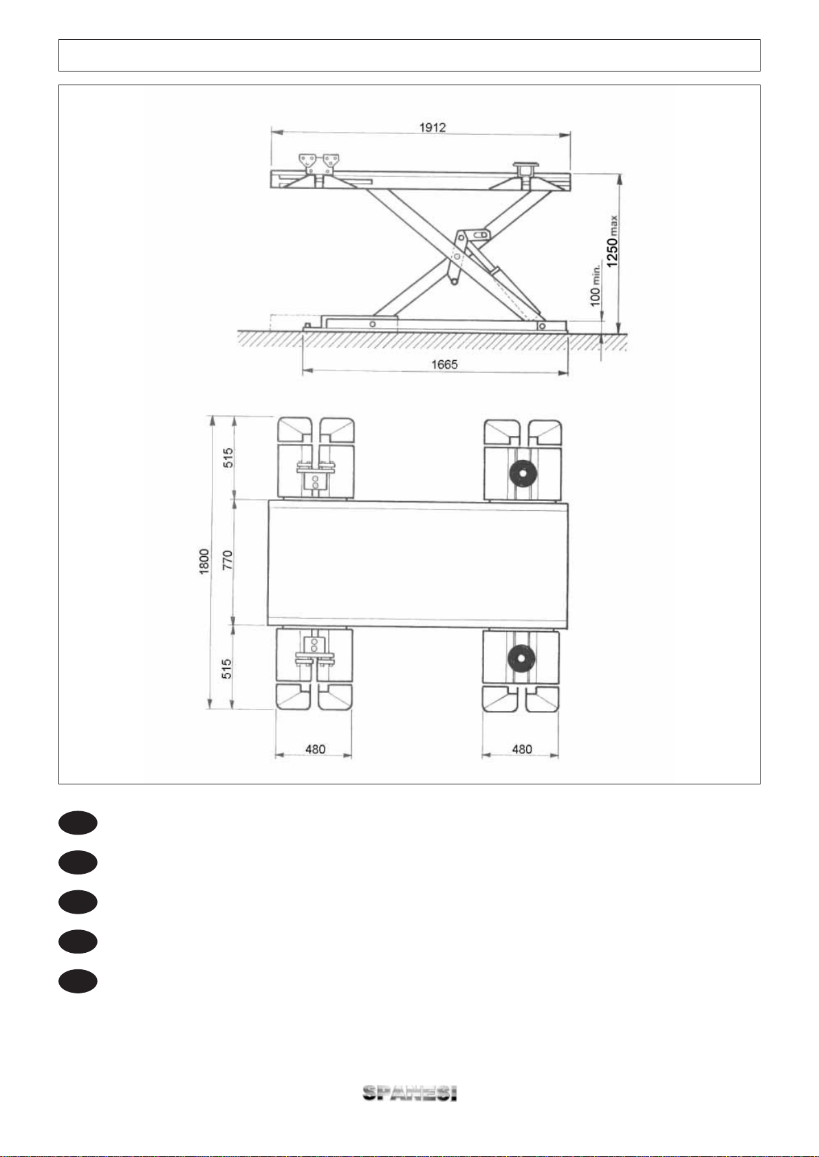
20
iMinibench
FIGURA 1 MINIBENCH - Dimensioni d'ingombro sollevatore
I
FIGURE 1 MINIBENCH - Overall lift dimensions
GB
FIGURE 1 MINIBENCH - Dimensions d'encombrement de l'élévateur
F
ABBILDUNG 1 MINIBENCH -Abmessungen Heber
D
FIGURE 1 MINIBENCH - Dimensiones ocupadas por el levantador
E
Table of contents
Other spanesi Lifting System manuals


Popular Lifting System manuals by other brands

WERTHER INTERNATIONAL
WERTHER INTERNATIONAL 442 LP manual

Wurtec
Wurtec FALSE CAR NAV2 installation guide

Hinowa
Hinowa LIGHTLIFT 1775 PERFORMANCE Quick instructions

salmson
salmson LIFTSON M Installation and starting instructions

RED ROOSTER
RED ROOSTER TMH-10T-CH user manual

stellar labs
stellar labs Slider34 owner's manual

Guldmann
Guldmann GLS5.1 user manual

WERTHER INTERNATIONAL
WERTHER INTERNATIONAL 208I/A Instruction and maintenance manual

Snorkel
Snorkel MB26J Operator's manual

Harmar Mobility
Harmar Mobility AL500 owner's manual

Aqua Creek Products
Aqua Creek Products Pro Pool-XR Deep Draft manual

Genie
Genie GTH-1544 Service and repair manual


