Aerotech ANT130LZ Series User manual

Revision 2.01
ANT130LZ Series Single-Axis Z Direct-Drive
Nanopositioning Stage
HARDWAREMANUAL

GLOBALTECHNICALSUPPORT
Go to the Global Technical Support Portal for information and support about your
Aerotech, Inc. products. The website supplies software, product manuals, Help files,
training schedules, and PC-to-PC remote technical support. If necessary, you can
complete Product Return (RMA) forms and get information about repairs and spare
or replacement parts. To get help immediately, contact a service office or your sales
representative. Include your customer order number in your email or have it
available before you call.
This manual contains proprietary information and may not be reproduced,
disclosed, or used in whole or in part without the express written permission of
Aerotech, Inc. Product names mentioned herein are used for identification purposes
only and may be trademarks of their respective companies.
Copyright © 2015-2023, Aerotech, Inc., All rights reserved.

Table of Contents
ANT130LZ Series Single-Axis Z Direct-Drive Nanopositioning Stage 1
Table of Contents 3
List of Figures 4
List of Tables 5
EU Declaration of Incorporation 6
UKCADeclaration of Incorporation 7
Safety Procedures and Warnings 8
Installation and Operation 9
Electrical Warnings 10
Motor-Related Warnings 11
Pinch Points 12
Magnetic Hazards 13
Handling and Storage 14
Chapter 1: Overview 17
1.1. Environmental Specifications 18
1.2. Accuracy and Temperature Effects 18
1.3. Basic Specifications 19
1.4. Air Requirements 20
Chapter 2: Installation 21
2.1. Dimensions 21
2.2. Securing the Stage to the Mounting Surface 22
2.2.1. Setting up the Pneumatic Counterbalance 24
2.3. Attaching the Payload to the Stage 26
Chapter 3: Electrical Installation 29
3.1. Motor and Feedback Connectors 30
3.2. Motor and Feedback Wiring 34
3.3. Motor and Feedback Specifications 36
3.4. Limits, Marker, and Machine Direction 38
3.5. Motor and Feedback Phasing 39
Chapter 4: Maintenance 41
4.1. Service and Inspection Schedule 41
4.2. Cleaning and Lubrication 42
4.3. Counterbalance Maintenance 44
4.4. Troubleshooting 45
Appendix A: Warranty and Field Service 47
Appendix B: Revision History 49
Index 51
Hardware Manual ANT130LZ
www.aerotech.com 3

List of Figures
Figure 1-1: GEN2 vs GEN1 Visual Comparison 17
Figure 1-2: Counterbalance Air Flow vs. Counterbalance Pressure 20
Figure 1-3: Air Inlet Location 20
Figure 2-1: ANT130LZ Dimensions 21
Figure 2-2: Mounting Hole Pattern (and Pneumatics Cylinder Clearance) 23
Figure 2-3: Counterbalance Pressure vs. External Payload 24
Figure 2-4: Load Orientations 28
Figure 2-5: Cantilevered Load Capabilities 28
Figure 3-1: ANT130LZMotor and Feedback Wiring [-CN1 Option] 34
Figure 3-2: ANT130LZMotor and Feedback Wiring [-CN2 Option] 35
Figure 3-3: Machine Direction 38
Figure 3-4: Hall Phasing Diagram 39
Figure 3-5: Encoder Phasing Reference Diagram (Standard/Square Wave) 40
Figure 3-6: Digital Encoder Phasing Reference Diagram (Sine Wave) 40
ANT130LZ Hardware Manual
4 www.aerotech.com

List of Tables
Table 1-1: Model Numbers and Ordering Options 17
Table 1-2: Environmental Specifications 18
Table 1-3: ANT130LZ Series Specifications 19
Table 2-1: Stage Mounting Surface Flatness Requirement 22
Table 2-2: Stage to Mounting Surface Hardware 23
Table 2-3: Payload Mounting Surface Flatness Requirement 26
Table 2-4: Payload to Stage Surface Hardware 26
Table 3-1: 25-Pin Motor and Feedback Connector Pinout (-CN1) 31
Table 3-2: 25-Pin Mating Connector Part Numbers 31
Table 3-3: 4-Pin Motor Connector Pinout (-CN2 Option) 32
Table 3-4: 4-Pin Motor Mating Connector Part Numbers 32
Table 3-5: 25-Pin Feedback Connector Pinout (-CN2 Option) 33
Table 3-6: 25-Pin Feedback Mating Connector Part Numbers 33
Table 3-7: Hall-Effect Sensor Specifications 36
Table 3-8: Thermistor Specifications 36
Table 3-9: Encoder Specifications 36
Table 3-10: Encoder Resolution 36
Table 3-11: Limit Switch Specifications 37
Table 3-12: ANT130LZ Motor Specifications 37
Hardware Manual ANT130LZ
www.aerotech.com 5

EU Declaration of Incorporation
Manufacturer Aerotech, Inc.
101 Zeta Drive
Pittsburgh, PA 15238-2811
USA
herewith declares that the product:
ANT130LZ stage
is intended to be incorporated into machinery to constitute machinery covered by the Directive 2006/42/EC
as amended; and that the following harmonized European standards have been applied:
EN ISO 12100:2010
Safety of Machinery - Basic concepts, general principles for design
EN 60204-1:2010
Safety of Machinery - Electrical equipment of machines - Part 1:General
requirements
and further more declares that
it is not allowed to put the equipment into service until the machinery into which it is to
be incorporated or of which it is to be a component has been found and declared to
be in conformity with the provisions of the Directive 2006/42/EC and with national
implementing legislation, for example, as a whole, including the equipment referred
to in this Declaration.
This is to certify that the aforementioned product is in accordance with the applicable requirements
of the following directive(s):
EU 2015/863 Directive, Restricted Substances (RoHS 3)
Authorized
Representative: / Norbert Ludwig
Managing Director
Aerotech GmbH
Gustav-Weißkopf-Str.18
90768 Fürth
Germany
Engineer Verifying
Compliance / Alex Weibel
Aerotech, Inc.
101 Zeta Drive
Pittsburgh, PA 15238-2811
USA
Date 2/22/2023
ANT130LZ Hardware Manual
6 www.aerotech.com

UKCADeclaration of Incorporation
Manufacturer Aerotech, Inc.
101 Zeta Drive
Pittsburgh, PA 15238-2811
USA
herewith declares that the product:
ANT130LZ stage
To which this declaration relates, meets the essential health and safety requirements and is in
conformity with the relevant UK Legislation listed below:
Supply of Machinery (Safety) Regulations 2008
Hazardous Substances in Electrical and Electronic Equipment Regulations
2012
Using the relevant section of the following UK Designated Standards and other normative
documents when installed in accordance with the installation instructions supplied by the
manufacturer.
EN ISO 12100:2010
Safety of Machinery - Basic concepts, general principles for design
EN 60204-1:2010
Safety of Machinery - Electrical equipment of machines - Part 1:General
requirements
and furthermore declares that it is not allowed to put the product into service until the machinery
into which it is to be incorporated or of which it is to be a component has been found and declared
to be in conformity with the provisions of the Supply of Machinery (Safety) Regulations 2008 UK
Legislation and with national implementing legislation, for example, as a whole, including the
equipment referred to in this Declaration.
Authorized
Representative: / Simon Smith
Managing Director
Aerotech Ltd
The Old Brick Kiln, Ramsdell, Tadley
Hampshire RG26 5PR
UK
Engineer Verifying
Compliance / Alex Weibel
Aerotech, Inc.
101 Zeta Drive
Pittsburgh, PA 15238-2811
USA
Date 2/22/2023
Hardware Manual ANT130LZ
www.aerotech.com 7

Safety Procedures and Warnings
IMPORTANT: This manual tells you how to carefully and correctly use and operate the
stage.
lRead all parts of this manual before you install or operate the stage or before you do
maintenance to your system.
lTo prevent injury to you and damage to the equipment, obey the precautions in this
manual.
lAll specifications and illustrations are for reference only and were complete and
accurate as of the release of this manual. To find the newest information about this
product, refer to www.aerotech.com.
If you do not understand the information in this manual, contact Aerotech Global
Technical Support.
IMPORTANT: This product has been designed for light industrial manufacturing or
laboratory environments. If the product is used in a manner not specified by the
manufacturer:
lThe protection provided by the equipment could be impaired.
lThe life expectancy of the product could be decreased.
Safety notes and symbols are placed throughout this manual to warn you of the potential risks at the
moment of the safety note or if you fail to obey the safety note.
Shock/Electrocution Hazard Pinch, Shear, or Crush Hazard
General/Conditional Awareness Rotational Machinery Hazard
Hot Surface Hazard Pinch/Entanglement Hazard
Magnetic Field Hazard Trip Hazard
Heavy, Bulky Lifting Hazard Appropriate Equipment Required
Pressure/Explosive Atmosphere
Hazard Electrostatic Discharge Hazard
A blue circle symbol is an action or tip that you should obey. Some examples include:
General tip Read the manual/section
Wear personal protective equipment
(PPE): Safety Glasses If applicable, do not lift unassisted
Wear personal protective equipment
(PPE): Gloves
Wear personal protective equipment
(PPE): Hearing Protection
ANT130LZ Hardware Manual
8 www.aerotech.com

Installation and Operation
To decrease the risk of damage to the equipment, you must obey the precautions that follow.
DANGER: General Hazard Warning!
This product can produce high forces and move at velocities that could cause injury.
The user is responsible for its safe operation. The following general equation is
provided to assist with risk assessments in regards to contact and pinch points:
WARNING: General Hazard Warning!
lOnly trained operators should operate this equipment.
lAll service and maintenance must be done by approved personnel.
lUse this product only in environments and operating conditions that are approved in
this manual.
lNever install or operate equipment that appears to be damaged.
lMake sure that the product is securely mounted before you operate it.
lUse care when you move the ANT130LZ or you could negatively affect the per-
formance of it.
WARNING:Trip Hazard!
Route, house, and secure all cables, duct work, air, or water lines. Failure to do so could
introduce trip hazards around the system that could result in physical injury or could
damage the equipment.
Hardware Manual ANT130LZ
www.aerotech.com 9

Electrical Warnings
To decrease the risk of electrical shock, injury, death, and damage to the equipment, obey the
precautions that follow.
DANGER: Electrical Shock Hazard!
lStage motor phase voltage levels could be hazardous live.
lPersonnel are protected from hazardous voltages unless electrical interconnections,
protective bonding (safety ground), or motor/stage enclosures are compromised.
lDo not connect or disconnect stage/motor interconnections while connected to a live
electrical power source.
lBefore you set up or do maintenance, disconnect electrical power.
lIt is the responsibility of the End User/System Integrator to make sure that stages are
properly connected and grounded per Engineering Standards and applicable safety
requirements.
lIt is the responsibility of the End User/System Integrator to configure the system
drive or controller within the Aerotech motor/stage electrical and mechanical
specifications.
ANT130LZ Hardware Manual
10 www.aerotech.com

Motor-Related Warnings
Aerotech motors are capable of producing high forces and velocities. Obey all warnings and all
applicable codes and standards when you operate a system that incorporates Aerotech motors.
DANGER: Mechanical Hazard!
Personnel must be made aware of the mechanical hazards during set up or when you
do service to the stage.
lWhen the system is not electrically energized (disabled), linear stage/motors can still
allow a stage carriage to move freely. This can create mechanical hazards such as
pinch or crush points.
lUnintentional manual movement into the stage "end-of-travel" stops, could damage
the stage or undo precision alignments.
lStage movement could create pinch points, entanglement hazards, or rotational
mechanical hazards.
DANGER: Hot Surface Hazard!
lThe stage/motor frame temperature could exceed 70°C in some applications.
lDo not touch the stage/motor frame while it is in operation.
lWait until the stage/motor has cooled before you touch it.
DANGER:Risk of Explosive Atmosphere!
lStandard Aerotech stage/motors are not rated for applications with explosive
atmospheres such as airborne dust or combustible vapors.
lDo not operate stage/motors outside of Aerotech environmental specifications.
DANGER: Magnetic Field Hazard!
Aerotech stage/motors contain magnets which can present a Magnetic Field Hazard.
lDo not disassemble a stage motor under any circumstances.
lStrong magnetic fields could interfere with external/internal medical devices.
lStrong magnetic fields could present mechanical hazards such as pinch points.
Hardware Manual ANT130LZ
www.aerotech.com 11

Pinch Points
A pinch point is a mechanical hazard that can occur when there are exposed parts of the stage or
system that can move. For example, the travel of a stage tabletop could expose the user to a pinch
point between the tabletop and the stage housing. The images that follow will show you typical
external and internal pinch point locations.
DANGER: Mechanical Hazard!
lSystem travel can cause crush, shear, or pinch injuries.
lOnly trained operators should operate this equipment.
lDo not put yourself in the travel path of machinery.
lRestrict access to all motor and stage parts
owhen the system moves under power (during normal operation, for example).
owhen the system is moved manually (during the installation process or when you
do maintenance, for example).
lMotors are capable of very high speeds and acceleration rates.
Figure 1: Typical Pinch Point Locations
ANT130LZ Hardware Manual
12 www.aerotech.com

Magnetic Hazards
The magnet track will be exposed during normal operation or when you do maintenance to the
system.
DANGER: Magnetic Field Hazard!
lOnly qualified, trained personnel should be allowed to have access to exposed mag-
net tracks during setup or when you do maintenance.
lStrong magnetic fields are present near and inside the magnet track assembly.
lDo no disassemble the magnet track components. If you do so, you will expose your-
self to mechanical crush, pinch, or impact hazards.
lMagnetic fields could interfere with external or internal medical devices (pace-
makers, for example).
lMagnetic fields can create mechanical hazards (crush, impact, or pinch points, for
example).
lLoose items such as metallic tools, watches, or keys could get drawn into and dam-
age the magnet track assembly.
IMPORTANT: Use non-magnetic tools when you install or do service to the stage.
Figure 2: Exposed Magnet Locations
Hardware Manual ANT130LZ
www.aerotech.com 13

Handling and Storage
IMPORTANT: It is the responsibility of the customer to safely and carefully lift and
move the stage.
lBe careful when you move or transport the stage.
lRetain the shipping materials for future use.
lTransport or store the stage in its protective packaging.
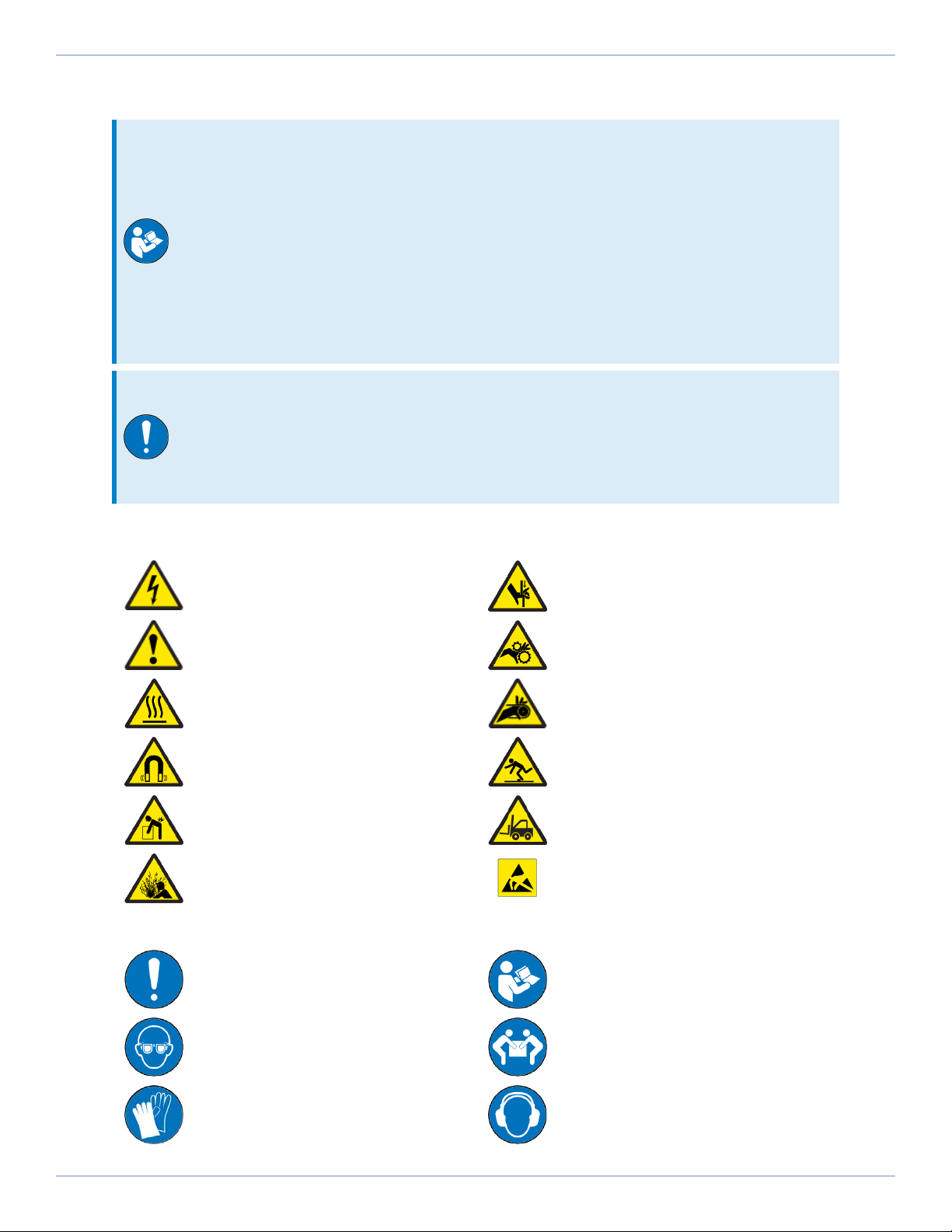
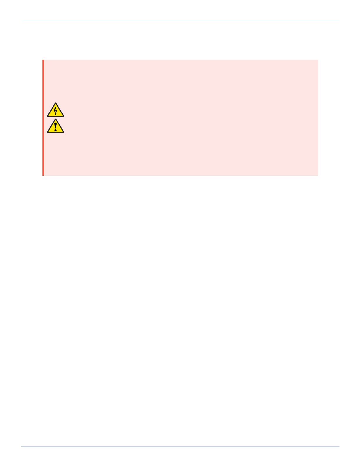
WARNING: Electrostatic Discharge (ESD) Sensitive Components!
Wear an ESDwrist strap when you handle, install, or do service to the system assembly.
You could damage the power supply or drives if you fail to observe the correct
ESDpractices.
Inspect the shipping container for any evidence of shipping damage. If any damage exists, notify the
shipping carrier immediately.
Remove the packing list from the shipping container. Make sure that all the items specified on the
packing list are contained within the package.
The documentation for the stage is on the included installation device. The documents include
manuals, interconnection drawings, and other documentation pertaining to the system. Save this
information for future reference.
Each stage has a label listing the system part number and serial number. These numbers contain
information necessary for maintenance or system hardware and software updates. Locate this label
and record the information for later reference.
Unpacking and Handling
It is the responsibility of the customer to safely and carefully lift and move the stage.
IMPORTANT: All electronic equipment and instrumentation is wrapped in antistatic
material and packaged with desiccant. Ensure that the antistatic material is not
damaged during unpacking.
DANGER:Lifting Hazard! Use care when you move the ANT130LZ or you could
negatively affect the performance of it.
lUse the correct lifting techniques, mechanical assistance, or additional help to lift or
move this product.
lDo not use the cables or the connectors to lift or move this product.
lMake sure that all moving parts are secure before you move the stage. Unsecured
moving parts could shift and cause injury or damage to the equipment.
lIf the stage is heavy, a single person lift could cause injury. Use assistance when you
lift or move it.
oRefer to Section 2.1. Dimensions for dimensions
oRefer to Section 1.3. Basic Specificationsfor weight specifications.
Carefully remove the stagefrom its protective shipping container.
lLift this product only by the vertical mounting bracket.
To access the vertical mounting bracket, you must first remove the pneumatic cover. Refer to Fig-
ure 3.
lFor multi-axis assemblies, always lift the system by the lower axis.
lUse a cart, dolly, or similar device to move the stage to a new location.
ANT130LZ Hardware Manual
14 www.aerotech.com

Gently set the stage on a smooth, flat, and clean surface. Use compressed nitrogen or clean, dry, oil-
free air to remove any dust or debris that has collected during shipping.
Before you operate the stage, let it stabilize at room temperature for at least 12 hours. This will
ensure that all of the alignments, preloads, and tolerances are the same as they were when they
were tested at Aerotech.
Each stage has a label listing the system part number and serial number. These numbers contain
information necessary for maintenance or system hardware and software updates. Locate this label
and record the information for later reference.
Red, anodized aluminum shipping brackets have been installed to prevent unwanted motion
damage that could occur during shipment. The brackets must be removed before the ANT130LZ can
be operated. Retain the brackets and hardware for future use.
DANGER: Mechanical Hazard!
lThe product can move manually without electrical power connected.
lWhen the shipping brackets are removed, the operator could be exposed to pinch
points.
Figure 3: Shipping Brackets
Storage
Store the stage in the original shipping container. If the original packaging included ESDprotective
packaging, make sure to store the stage in it. The storage location must be dry, free of dust, free of
vibrations, and flat.
Refer to Section 1.1. Environmental Specifications
Hardware Manual ANT130LZ
www.aerotech.com 15

This page intentionally left blank.
ANT130LZ Hardware Manual
16 www.aerotech.com

Chapter 1: Overview
The specifications in this manual pertain to the second generation of ANT130LZ stages. The ordering
options (Table 1-1) and basic specifications (Section 1.3.) have changed. The visual differences
between second and first generation stages:
lan updated Aerotech logo
land the introduction of additive (3D-printed) parts.
Refer to Figure 1-1. Contact Aerotech if you need a first generation manual.
Figure 1-1: GEN2 vs GEN1 Visual Comparison
Table 1-1: Model Numbers and Ordering Options
ANT130LZ Series Linear Motor Stage
Travel (Required)
-035 35 mm travel
-060 60 mm travel
Feedback (Required)
-E1 Incremental linear encoders, 1 Vpp amplified sine output
-E2 Incremental linear encoders, digital RS422 output, 5 nm electrical
resolution
-E3 Absolute linear encoder
-E4 Incremental linear encoders, 1 Vpp amplified sine output, high-
performance
Connectors (Required)
-CN1 Integral cable with a 25-pin D-style motor and feedback connector
-CN2 Integral Y cable with 4-pin high-powered D-style motor and 25-pin D-
style feedback connectors
Note: -CN1 option not valid for systems using bus voltages greater than 80 V
Performance Grade (Required)
-PL1 Base performance
-PL2 High-accuracy performance
Integration (Required)
-TAS Test as system: Testing, integration, and documentation of a group of
components as a complete system that will be used together.
-TAC Test as components:Testing and integration of individual items as
discrete components that ship together.
Hardware Manual ANT130LZ
www.aerotech.com 17

1.1. Environmental Specifications
WARNING:General Hazard Warning! Do not expose this product to environments or
conditions outside of the listed specifications. You could damage the equipment if you
exceed the environmental or operating specifications.
DANGER:Risk of Explosive Atmosphere!
lStandard Aerotech stage/motors are not rated for applications with explosive
atmospheres such as airborne dust or combustible vapors.
lDo not operate stage/motors outside of Aerotech environmental specifications.
Table 1-2: Environmental Specifications
Ambient
Temperature
Operating: 10° to 35° C (50° to 95° F)
The optimal operating temperature is 20° C ±2° C (68° F ±4° F). If at any time the
operating temperature deviates from 20° C degradation in performance could
occur.
Storage: 0° to 40° C (32° to 104° F) in original shipping packaging
Humidity Operating: 20% to 60% RH
Storage: 10% to 70% RH, non-condensing in original packaging.
The stage should be packaged with desiccant if it is to be stored for an extended
time.
Altitude Operating: 0 m to 2,000 m (0 ft to 6,562 ft) above sea level
Contact Aerotech if your specific application involves use above 2,000 m or below
sea level.
Vibration Use the system in a low vibration environment. Floor or acoustical vibration can
affect system performance. Contact Aerotech for information regarding your
specific application.
Protection
Rating
These stages are not suited for dusty or wet environments. This equates to an
ingress protection rating of IP00.
Use Indoor use only
1.2. Accuracy and Temperature Effects
Aerotech products are designed for and built in a 20°C (68°F) environment. Temperature changes
could cause a decrease in performance or permanent damage to the stage. At a minimum, the
environmental temperature must be controlled to within 0.25ºC per 24 hours to ensure the stage
specifications are repeatable over an extended period of time. The severity of temperature effects
on all specifications depends on many different environmental conditions, which include how the
stage is mounted. Contact the factory for more details.
The thermal expansion coefficient of the encoder scale is 3.25 ppm/°C. Travel will increase or
decrease at this rate as the temperature of the encoder scale temperature deviates from 20°C (68°F).
The accuracy specification of stage is measured 25 mm above the table with the stage in an
unloaded condition. The stage is assumed to be fully supported by a mounting surface meeting or
exceeding the specification in Section 2.2.
ANT130LZ Hardware Manual
18 www.aerotech.com

1.3. Basic Specifications
Resolution is dependent on encoder resolution and controller interpolation.
Table 1-3: ANT130LZ Series Specifications
ANT130LZ-035 ANT130LZ-060
Travel 35 mm 60 mm
Accuracy (1)
-PL1 ±3.0 µm
-PL2 (-E1, -E2) ±300 nm
-PL2 (-E4) ±200 nm
Bidirectional Repeatability (1)
±75 nm
Resolution (Minimum
Incremental Motion)
-E1 2 nm
-E4 1 nm
Straightness (1) ±2.0 µm
Flatness (1) ±2.0 µm
Pitch 10 arc sec
Roll 10 arc sec
Yaw 5 arc sec
Maximum Speed (2) -E1, -E4 200 mm/s
-E2 145 mm/s
Maximum Acceleration (No Load) (2) 1 g
In-Position Stability (3) -E1 <2 nm
-E4 <1 nm
Load Capacity (Vertical) (4) 10.0 kg
Moving Mass 1.3 kg 1.5 kg
Stage Mass 5.0 kg 5.7 kg
Material Anodized Aluminum
Mean Time Between Failure 30,000 Hours
1. Certified with each stage.
2. Requires the selection of an applicable amplifier with sufficient voltage and current.
3. In-position stability is reported as 3-sigma value (requires a 1 Vpp encoder).
4. Payload specifications assume that the payload is centered on-axis.
5. Specifications are for single-axis systems measured 25 mm above the tabletop; performance of multi-axis system
depend upon the payload and workpoint. Consult the Aerotech factory for multi-axis or non-standard applications.
6. -PL2 performance requires the use of an Aerotech controller.
7. To ensure the achievement and repeatability of specifications over an extended period of time, environmental
temperature must be controlled to within 0.25°C per 24 hours. Consult the Aerotech factory for more information.
8. The air supply for the pneumatic counterbalance must be clean, dry to 0°F dewpoint, and filtered to 0.25 µm or better.
Use nitrogen at 99.9% purity for best results. Supply pressure is determined by the amount of payload carried by the stage.
Hardware Manual ANT130LZ
www.aerotech.com 19

1.4. Air Requirements
The air supply to the counterbalance should be clean and liquid water should not be present.
lIf nitrogen is used, it must be 99.99% pure and filtered to 0.25 microns. [Recommended]
lIf compressed air is used, it must be filtered to 0.25 microns, dry to 0º F dew point, and oil free.
The maximum allowable input pressure specification is 0.6 MPa (87 psi).
The low friction air cylinder consumes air as described in Figure 1-2.
Figure 1-2: Counterbalance Air Flow vs. Counterbalance Pressure
Figure 1-3: Air Inlet Location
ANT130LZ Hardware Manual
20 www.aerotech.com
This manual suits for next models
2
Table of contents
Other Aerotech Lifting System manuals
Popular Lifting System manuals by other brands

morse
morse 525-N-114 Operator's manual

Kuzar
Kuzar K-31 user manual

WMB
WMB TE-076 Operating instructions & user manual

Draper
Draper AeroLift 100 220V Installation & operation instructions

APlusLift
APlusLift HW-9KOH Installation manual & operation instructions

AMGO
AMGO HS-12 Installation and service manual